 English
 English
 русский
 日本語
 Español
 中文简体

The SANTO UFA range of self-regulating heating cables is mainly used for frost protection of pipes and vessels but can also be used to maintain processes up to 65°C. These heating cables are available...
See Details
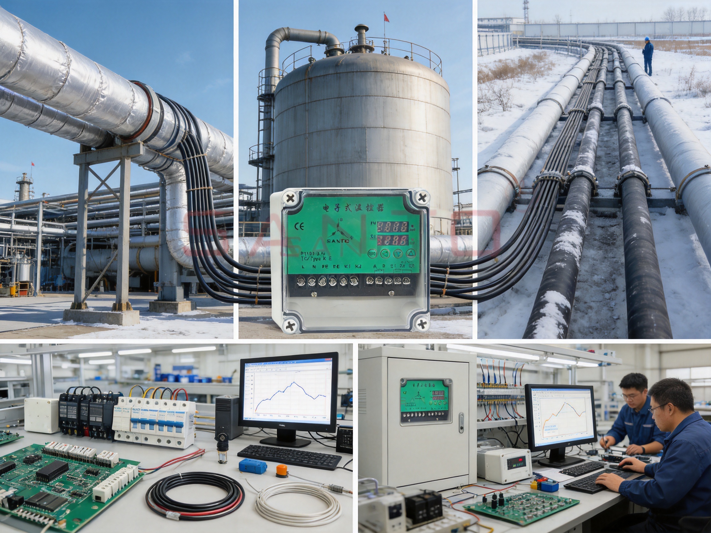
Accurate temperature control is essential in electric heat tracing systems. Whether a traced pipeline must be protected from freezing, a process vessel must remain within a defined operating range, or an outdoor surface requires controlled deicing, the quality of the thermostat directly affects safety, energy consumption, maintenance requirements, and system service life. The DATC-D single-loop electronic thermostat with dual displays is designed to provide dependable control and centralized monitoring for one heat tracing circuit.
Unlike a basic mechanical thermostat, this cabinet-mounted electronic controller combines temperature measurement, configurable control algorithms, alarm management, output flexibility, communication capability, non-volatile memory, and clear visual indication in one compact device. Its dual-display arrangement allows the operator to view process values and set points separately, simplifying commissioning and everyday supervision.
The controller is manufactured by Santo Thermal Control Technology Co., Ltd., a specialized producer of electric heating and thermal control products in China. The company has developed a broad product portfolio covering self-regulating heating cables, constant-power heating cables, silicone rubber heating systems, mineral-insulated cables, snow-melting cables, underfloor heating products, tubing bundles, and related accessories. This product experience provides an important foundation for designing controllers specifically suited to heat tracing applications.
Content
The DATC-D is intended for close temperature control of one heat tracing circuit. It is normally installed in a control cabinet or distribution board located in an indoor, non-hazardous area. From this location, the controller receives a signal from a temperature sensor, compares the measured process temperature with the configured set point, and sends a control signal to the heating equipment.
A single-loop arrangement is particularly suitable for applications in which one sensor and one controlled heating circuit can maintain the required thermal condition. Examples include pipe freeze protection, tank temperature maintenance, valve and pump protection, process line temperature control, roof and gutter deicing, and other industrial or commercial heating tasks.
The controller can operate with several sensor types, including Pt100, Pt1000, KTY11-6, and multiple thermocouple types. It can also accept current or voltage input signals, allowing the device to be integrated with transmitters and other instrumentation where required. This broad input compatibility helps users select a sensing method appropriate to the installation environment, process temperature, cable distance, and existing control architecture.
At the factory, the DATC-D is configured for on/off control, which is widely used for heat tracing. However, users can select proportional, proportional-integral, proportional-derivative, or proportional-integral-derivative control modes. Automatic adjustment functions are also available for applications that require more refined regulation than simple switching control.
One of the most visible advantages of the DATC-D is its two-display design. The controller uses two 7-segment LED displays, supported by yellow and green status indicators. One display can show the measured process value while the other presents the set point or configuration value. This arrangement avoids the need to alternate constantly between two readings on a single screen.
During initial setup, the dual displays provide direct visual guidance. Installers can observe the measured temperature while adjusting the target value, checking sensor response, and verifying the operation of the output. This makes commissioning more efficient and reduces the possibility of entering or interpreting settings incorrectly.
During normal operation, the operator can quickly determine whether the process temperature is approaching, meeting, or moving away from the set point. A separate display for the target value also makes it easier to identify an incorrect setting, an unexpected process condition, or a sensor issue.
The status LEDs provide additional information about operating conditions. Depending on the operating state and configured functions, the indicators can help show power, control activity, alarm conditions, or other status information. Together, the numerical displays and status lights provide a straightforward interface suitable for cabinet-mounted equipment.
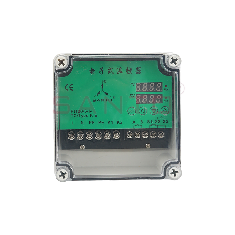
DATC-D single-loop electronic ther at with dual displays
Heat tracing systems do not all respond in the same way. A short pipe with low thermal mass may react quickly to heating, while an insulated process vessel may respond slowly. Some applications require simple temperature maintenance, while others benefit from gradual output adjustment. The DATC-D accommodates these differences through multiple control modes.
On/off control is the standard factory configuration and is often appropriate for electric heat tracing. The controller switches the heating output on when the measured temperature falls below the control range and switches it off when the required temperature has been reached. A defined switching differential can help prevent excessive relay cycling.
This mode is simple, easy to understand, and compatible with contactors, solid-state relays, and other switching devices. It is commonly selected for freeze protection, basic temperature maintenance, and applications in which a small temperature variation around the set point is acceptable.
Proportional control varies the output in relation to the difference between the measured temperature and the set point. When the temperature is far below the target, the controller can apply a stronger output. As the temperature approaches the target, the output can be reduced. This may help limit overshoot and improve temperature stability in suitable applications.
For more demanding processes, the controller supports proportional-integral, proportional-derivative, and proportional-integral-derivative algorithms. Integral action can help reduce long-term deviation from the set point, while derivative action can respond to the rate of temperature change. A combined PID strategy may be useful where thermal inertia, changing load conditions, or process sensitivity require closer regulation.
The availability of these control modes gives the user greater freedom than a thermostat limited to mechanical switching or simple on/off operation. It also permits the same controller platform to be used across a broader range of heating installations.
Reliable temperature control begins with reliable temperature measurement. The DATC-D is designed to work with several common temperature sensor technologies, enabling the system designer to select an input according to the application.
| Input category | Supported examples | Typical application consideration |
|---|---|---|
| Resistance temperature detectors | Pt100 and Pt1000 | Accurate measurement for general industrial and process temperature monitoring |
| Thermistor-type sensor | KTY11-6 | Suitable for compatible low- and medium-temperature monitoring arrangements |
| Thermocouples | Types L, J, U, T, K, E, N, and S | Useful across a wide temperature range and for applications requiring thermocouple instrumentation |
| Current signal | 0/4–20 mA | Integration with transmitters and industrial control systems |
| Voltage signal | 0/2–10 V | Connection to compatible analog measurement devices |
The specified control range can extend from approximately -200°C to +2400°C, depending on the sensor type selected. The actual usable range is determined by the sensor, wiring, installation method, and process conditions. This flexibility allows the controller to be applied to low-temperature freeze protection as well as substantially higher-temperature monitoring duties when an appropriate sensor is used.
Measurement accuracy depends on the selected input. The supplied technical information identifies approximate error values of no more than 0.1% for Pt100 with three-wire connection, no more than 0.4% for Pt100 with two-wire connection, no more than 0.25% for thermocouple input including cold-junction effects, and no more than 0.1% for voltage and current inputs. Proper sensor selection and installation remain essential to achieving the expected performance.
The DATC-D is available in several hardware configurations. This allows the user to choose a controller that matches the required actuator and communication architecture instead of paying for functions that are not needed.
| Model configuration | Output arrangement | Potential use |
|---|---|---|
| DATC-D | Three SPST relay outputs and one logic output | Control of contactors, solid-state relays, and alarm functions |
| DATC-D/MA | Two SPST relay outputs and one analog output | Applications using analog actuators or thyristor control |
| DATC-D/COM | Three SPST relay outputs, one logic output, and RS-485 | Relay-based control with Modbus communication |
| DATC-D/COMA | Two SPST relay outputs, one analog output, and RS-485 | Analog actuator control combined with network integration |
The relay contacts are rated at 3 A and 230 VAC for the specified control and alarm functions. The expected service life is approximately 350,000 operations at rated current, or approximately 900,000 operations at 1 A under the stated conditions. The logic output is rated at approximately 0–12 V with a maximum current of 20 mA, allowing it to drive compatible solid-state switching equipment.
For models with analog output, the controller provides a 0/4–20 mA signal with a stated load resistance of up to 500 ohms. This output can drive compatible actuators, power controllers, or thyristor-based equipment. An analog approach may be preferred where smooth power adjustment is required instead of repeated mechanical switching.
The output selection is an important advantage for system integrators. A relay-based model can be connected to a mechanical contactor or solid-state relay, while an analog model can be used with a suitable power controller. This makes the controller adaptable to different heater capacities, switching frequencies, and electrical designs.
A thermostat should not merely switch a heater on and off. It should also identify conditions that can compromise the process or create a maintenance problem. The DATC-D continuously monitors the temperature input and can detect a disconnected or short-circuited sensor.
When a sensor fault is detected, the controller displays an alarm message. The control output can then change to a user-defined safe state, such as on or off. The correct selection depends on the application. For a freeze-protection system, keeping the heating circuit energized during a sensor fault may be appropriate if the installation has independent overtemperature protection. For another process, switching the heater off may be the safer response.
The controller can provide two independently configurable alarm relay outputs. Up to eight different temperature-triggered alarm functions can be defined for the input sensor according to the installation requirements and controller configuration. These functions can be used to indicate high temperature, low temperature, deviation from the set point, sensor failure, or other defined conditions.
Alarm outputs can be connected to visual indicators, audible alarms, building management systems, supervisory control systems, or maintenance notification equipment. By making abnormal conditions visible at an early stage, the controller helps reduce the risk of undetected heating failure or uncontrolled temperature rise.
The sensor-fault response is especially valuable in heat tracing. A damaged sensor can cause a conventional control system to operate incorrectly. If the heating system remains energized without accurate temperature feedback, the process or surrounding equipment may be exposed to excessive temperature. If the heater is incorrectly held off, pipes may freeze or a process may fall below its required temperature. The configurable fault state gives the system designer a practical way to address this risk.
The controller includes a startup delay function that can be activated after initial power-on. This function may be used to avoid simultaneous energization of multiple heating circuits during a system startup. In a facility with many traced lines, sequential startup can help reduce peak electrical demand and avoid unnecessary loading of upstream distribution equipment.
Startup delay can also be useful where a process requires a controlled warm-up sequence. Instead of immediately energizing every circuit when power is restored, the system can introduce a planned delay. The specific delay strategy should be selected by the system designer according to the available electrical capacity and process requirements.
A built-in service counter records relay operations and can issue an alarm when a configured operating threshold has been reached. This feature supports preventive maintenance. Relay wear is influenced by load current, switching frequency, inrush current, and actuator type. Tracking the number of operations gives maintenance personnel a practical indicator for inspection or replacement planning.
Using a service counter is more effective than relying solely on calendar-based maintenance. Two controllers operating in different applications may experience very different numbers of switching cycles. A counter allows maintenance decisions to be based on actual operating activity rather than an assumed average.
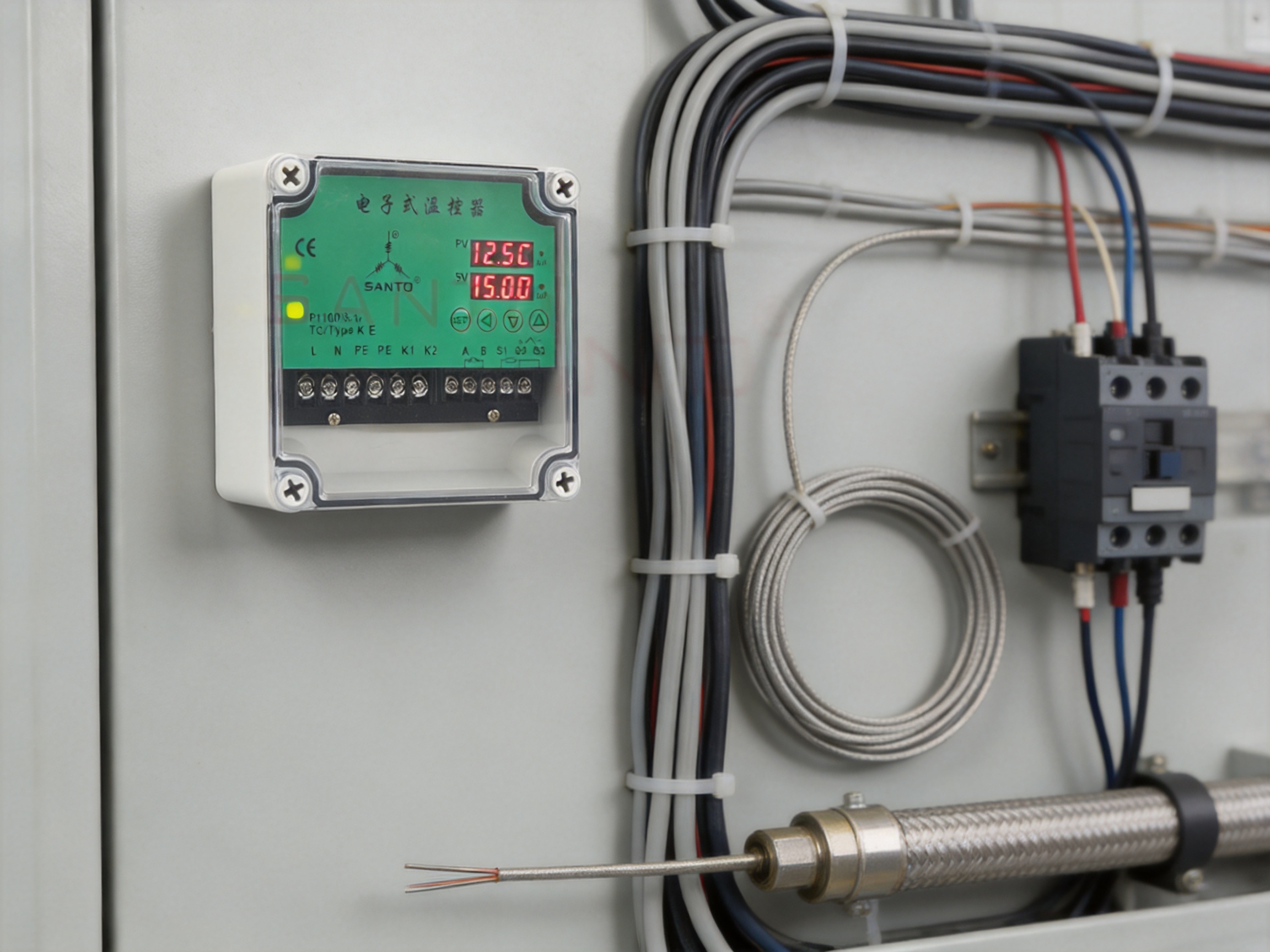
For installations requiring centralized monitoring, selected DATC-D models provide RS-485 communication using the Modbus protocol. Communication can be configured at 9,600, 19,200, or 38,400 bits per second. A network can include up to 32 devices under the stated configuration.
Communication allows operators to collect temperature values, set points, alarm states, output status, and other available operating information through a supervisory system. In a facility with numerous heat tracing circuits, this can reduce the need for routine manual inspection of individual cabinets.
Centralized monitoring is valuable in petroleum, chemical, gas, water treatment, food processing, building services, and infrastructure applications. A control room operator can identify a low-temperature alarm, sensor failure, or excessive switching condition and direct maintenance personnel to the affected area.
RS-485 communication also supports more organized data collection. Historical records can help identify seasonal operating patterns, insulation problems, changes in process loading, or recurring equipment faults. When combined with appropriate supervisory software, the thermostat becomes part of a larger thermal management system rather than an isolated panel component.
The communication option is available only on the relevant controller variants. Therefore, network requirements should be identified before ordering. Where computer-aided configuration is required, the optional DATC-D configuration interface and software can assist users with setup and parameter management.
The DATC-D uses EEPROM-based non-volatile memory for configuration data. Settings are retained after a power outage or extended shutdown. This is important for heat tracing systems installed in seasonal facilities, remote locations, or areas where power interruptions may occur.
Without retained configuration data, a controller might require manual reprogramming after an outage. That can delay restart, increase the possibility of setting errors, and require a technician to visit the cabinet. EEPROM storage helps preserve the operating parameters so that the controller can resume its intended function when power is restored, subject to the system’s startup and safety procedures.
Stored parameters may include the selected sensor type, set point, control mode, alarm settings, output behavior, and communication configuration. Users should maintain an approved record of these settings as part of the project documentation and verify them during commissioning.
The controller is designed for cabinet mounting and uses a plastic ABS housing suitable for installation on current distribution boards. The enclosure design follows IEC 61554 requirements for this type of panel equipment. Its compact construction helps conserve valuable cabinet space while providing the functions expected from an industrial electronic controller.
The front protection rating is IP65, while the rear is rated IP20 in accordance with DIN EN 60529. The front rating helps protect the user interface from dust and water jets when the controller is correctly installed with the appropriate panel sealing arrangement. The rear section is intended to be protected within the cabinet and should not be treated as a weatherproof enclosure.
The unit connects through threaded wiring terminals at the rear. The terminal blocks are pluggable, which can simplify installation, testing, replacement, and cabinet wiring operations. The supplied information specifies compatibility with solid conductors in the approximate range of 1.0 to 1.3 mm, or 1 mm conductors equipped with cable terminals. Actual wire selection should follow the applicable electrical code, project specifications, and terminal instructions.
The power supply is rated at 110–240 V with a tolerance of approximately -15%/+10%, at 48–63 Hz. Self-consumption is specified at less than 15 VA. This broad supply range allows the device to be used in electrical systems with different nominal voltages without requiring a separate transformer for each supply category.
Panel layout should account for the specified minimum spacing between the controller and cabinet circuit breakers. The technical information identifies minimum horizontal and vertical spacing of more than 8 mm under the stated configuration conditions. Adequate spacing supports safe wiring, ventilation, service access, and compliance with installation requirements.
The specified operating temperature range is -5°C to +55°C, while the storage temperature range is -40°C to +70°C. Relative humidity may be up to 90% without condensation. The controller can be installed in any permitted position, provided that the cabinet environment remains within the rated conditions.
Although the front panel has a high ingress protection rating, the complete installation must be evaluated as a system. Cabinet ventilation, condensation prevention, vibration, electromagnetic interference, ambient temperature, and proximity to high-power switching equipment can all influence controller reliability.
Heat tracing cabinets are often installed in industrial areas where electrical noise and temperature changes are present. The controller’s stated electromagnetic compatibility performance follows DIN EN 61326, Class B industrial requirements, while electrical safety is specified according to DIN EN 61010-1, overvoltage category III, pollution degree 2. Correct grounding, cable routing, shielding, and separation of sensor and power wiring remain essential for stable measurement.
Sensor extension cables should be selected and installed carefully. A three-wire shielded cable can be used for extending a suitable sensor, with the stated maximum resistance and length limitations observed. If the sensor cable runs through a conduit or near high-voltage support cables, shielding is recommended. The shield should normally be grounded at one end of the controller to help avoid ground-loop problems.
The controller’s technical documentation identifies compliance with DIN EN 61010-1 for electrical safety, overvoltage category III, pollution degree 2, and DIN EN 61326 for electromagnetic compatibility. These specifications provide a framework for integrating the device into appropriate indoor industrial control cabinets.
The DATC-D is intended for non-hazardous indoor areas unless the complete installation includes suitable certified equipment and protection measures. Hazardous-area temperature sensors and associated safety isolators must be selected according to the area classification and the project’s explosion-protection design.
The product information identifies MMP-PT100-EXE sensors for certain hazardous-area applications and MMP-PT100-NH sensors for non-hazardous areas. The correct sensor and interface arrangement must be confirmed before installation. In some configurations, the specified hazardous-area sensor can be connected directly to the controller input, while other arrangements may require an appropriate isolator. The installation manual and applicable local regulations must govern the final design.
Safety is also influenced by the heating load. The thermostat’s relay contacts should not be used beyond their rated electrical capacity. Larger heat tracing circuits normally require an appropriately sized contactor, solid-state relay, thyristor controller, or other power switching device. Independent overtemperature protection may also be required for critical processes or high-energy heating systems.
The DATC-D offers several practical advantages over simple mechanical thermostats and limited-function electronic switches.
Electronic measurement and configurable control algorithms provide greater flexibility and repeatability than a basic bimetallic thermostat. The selected sensor determines the achievable measurement performance, while the control mode can be adapted to the thermal behavior of the application.
Two independent numerical displays show process information and target information at the same time. This is particularly helpful during commissioning and troubleshooting because the operator can see whether the measured temperature is changing as expected.
Sensor disconnection and short-circuit conditions are identified automatically. Configurable alarms and user-defined fault output states provide a more controlled response than a thermostat that simply fails without notification.
Relay, logic, analog, and communication variants support different actuator types and control architectures. A user can select a model for contactor control, solid-state switching, thyristor operation, or supervisory integration.
Non-volatile memory retains configuration data during power loss. A startup delay can also reduce simultaneous demand when several circuits are energized after an outage.
The relay service counter provides information about actual switching activity. This is a useful addition for installations where relay wear and maintenance planning are important.
RS-485 Modbus models can connect multiple controllers to a central monitoring system. This is more suitable for large facilities than individual standalone thermostats that require local inspection.
Santo Thermal Control Technology Co., Ltd. combines thermal control manufacturing with the production of electric heating products. According to the supplied company information, the business has more than 35 years of industry experience and integrates research, product development, manufacturing, and sales.
The company’s product range includes automatic temperature-control heating belts, self-limiting heating belts, heat tracing belts, constant-power heating cables, glass-fiber heating belts, mineral-insulated cables, silicone rubber heating systems, snow-melting cables, underfloor heating products, tubing bundles, and accessories. This broad portfolio gives the manufacturer direct experience with the different electrical and thermal behaviors that controllers must manage.
A controller developed by a company involved in heating cable design can be evaluated in relation to real heat tracing loads rather than as a generic temperature instrument alone. The manufacturer can consider switching frequency, startup current, sensor placement, insulation quality, thermal response, environmental exposure, and the practical requirements of installation and maintenance.
The company states that it operates a research and product development program and has cooperated with Harvard University in the United States on product research. It also reports the establishment of an irradiation center, development of patented heating technologies, construction of a product simulation testing laboratory, and expansion of manufacturing capacity.
These capabilities support a product development process that can include material selection, electrical design, control parameter testing, thermal simulation, prototype evaluation, production inspection, and after-sales feedback. For a control product used with heating cables, this combined knowledge can help ensure that the controller is matched to the behavior of the complete heating system.
The company reports ISO9001 quality system certification and national CCC certification for its products. It also states that selected products have obtained explosion-proof and EAC Eurasian Union certifications. Certification requirements vary by product model and application, so purchasers should confirm the documentation applicable to the exact controller, sensor, and installation.
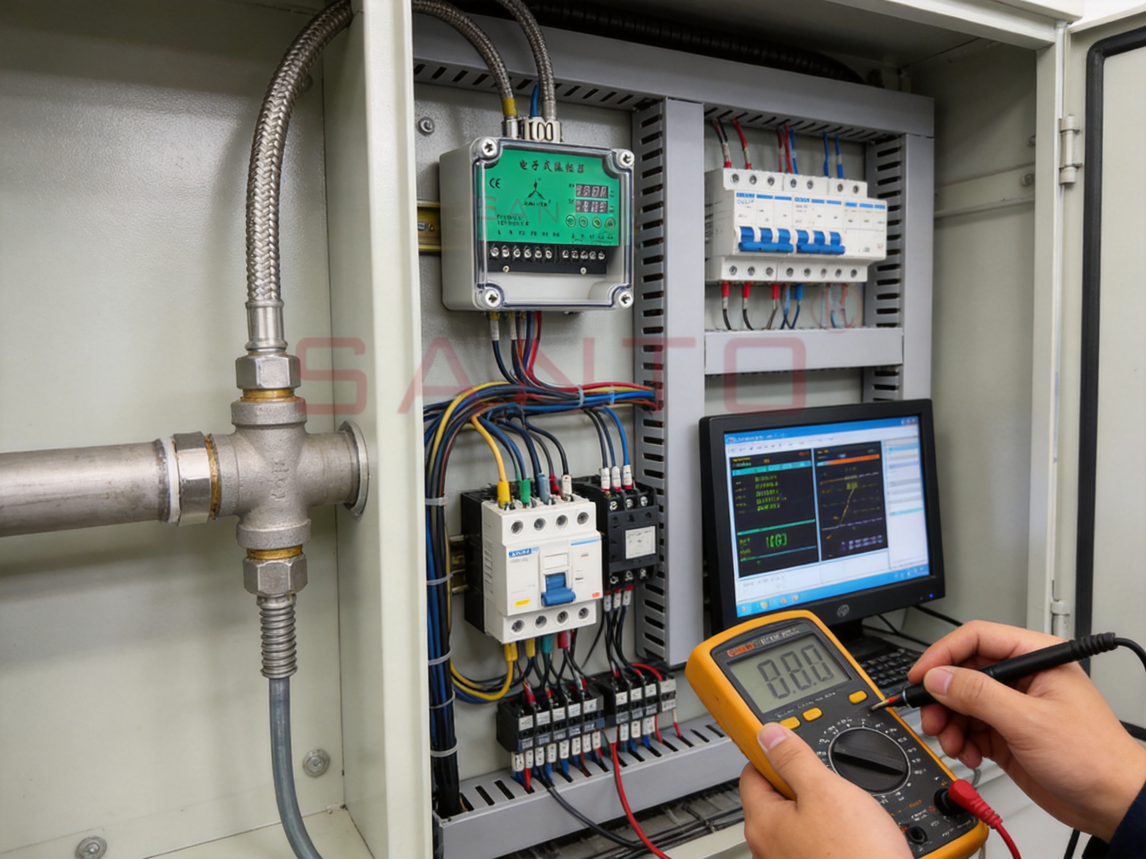
A reliable electronic thermostat depends on more than the visible housing and display. Consistent performance requires controlled manufacturing of the circuit board, accurate installation of electronic components, reliable terminal connections, stable firmware and parameter handling, and final functional testing.
The design process begins with the definition of input, output, environmental, and safety requirements. For the DATC-D, this includes support for multiple sensor types, broad supply voltage, configurable algorithms, alarm handling, optional communication, and compatibility with cabinet installation.
Engineering must also account for electrical isolation, signal conditioning, relay contact protection, analog output accuracy, electromagnetic compatibility, and heat dissipation. The use of different hardware variants allows the manufacturer to tailor each product configuration while preserving a common user interface and control concept.
Electronic components must be mounted and soldered consistently to support long-term operation in industrial cabinets. Printed circuit board assembly typically includes component placement, soldering, inspection, and electrical testing. Particular attention is required for relay contacts, terminal interfaces, power supply sections, analog signal circuits, and sensor input channels.
Quality control at this stage helps identify open circuits, solder defects, incorrect component placement, and communication problems before the product reaches final assembly. Automated or semi-automated inspection can be combined with operator checks and functional testing.
The controller’s operating functions depend on its embedded software and parameter structure. Firmware must correctly interpret sensor signals, calculate process values, apply the selected control algorithm, operate outputs, retain settings, display alarms, and communicate through Modbus where applicable.
Functional testing should verify the response to normal sensor inputs as well as abnormal conditions such as sensor disconnection, short circuit, out-of-range signals, power interruption, and communication failure. The service counter and startup delay should also be tested as part of the complete operating sequence.
Final inspection can include appearance checks, display verification, button and interface checks, insulation and dielectric tests where required, supply voltage tests, output switching tests, analog output calibration, alarm verification, and communication testing. Product identification and model marking are also important because the different variants have different output arrangements.
A documented quality process helps ensure that products supplied for repeat projects maintain consistent specifications. It also gives users and system integrators a clearer basis for inspection, acceptance testing, and troubleshooting.
The controller can regulate heating cables installed on water lines, fire-protection piping, condensate lines, process pipes, and other infrastructure exposed to freezing conditions. A low-temperature alarm can notify operators if the pipe temperature falls below a defined threshold or if the sensor fails.
In chemical, petroleum, gas, and manufacturing facilities, heat tracing is often used to maintain fluid viscosity, prevent crystallization, avoid solidification, or keep a process within a required operating range. The available PI, PD, and PID modes may be useful where the process has significant thermal inertia.
Storage tanks and vessels may require controlled heating to maintain product flowability or protect contents from low ambient temperatures. The thermostat can receive input from a suitable surface, immersion, or process sensor and control the associated heating equipment through a relay or analog output.
Snow and ice melting systems require reliable control to prevent unnecessary operation and energy consumption. A temperature sensor can be positioned to monitor the relevant surface or ambient condition, while the controller manages the heating circuit according to the configured set point and alarm strategy.
In suitable installations, the controller can manage underfloor heating mats or other electric surface heating systems. The actual sensor arrangement, maximum temperature, and independent safety controls must be selected according to the floor construction, occupancy requirements, and applicable regulations.
Heated tubing bundles and instrument lines often need stable temperature maintenance to prevent condensation, freezing, or changes in fluid properties. The compact cabinet-mounted format and multiple sensor inputs make the controller suitable for integration into a larger instrumentation and heat tracing package.
Before installation, verify the controller model, supply voltage, sensor type, output configuration, heater load, cabinet dimensions, environmental conditions, and communication requirements. The model designation should match the required relay, analog, logic, and RS-485 functions.
Install the controller in an indoor, non-hazardous cabinet unless the complete installation has been designed and certified for another environment. Maintain the recommended spacing from circuit breakers and other equipment. Ensure that the cabinet provides adequate protection from condensation, excessive heat, dust, vibration, and direct water exposure.
Route sensor wiring separately from high-voltage heater and switching cables where possible. Use shielded cable when the sensor wiring is exposed to electromagnetic interference. Ground the shield at the controller end only unless the project wiring standard specifies another arrangement.
Confirm the sensor wiring configuration, especially when using Pt100 in two-wire or three-wire form. Incorrect wiring can create measurement errors and may cause the controller to regulate at an incorrect temperature. Check the sensor location carefully so that it measures the protected pipe, vessel, surface, or process rather than a nearby ambient condition that does not represent the actual thermal requirement.
After wiring, verify the supply voltage and inspect all terminals. Confirm that the heating load is connected through an appropriately rated switching device. Test the controller with the heater isolated if necessary, then verify output operation under controlled conditions.
During commissioning, select the correct input type, configure the control range, enter the set point, choose the control mode, define alarm thresholds, set the sensor-fault response, and configure the startup delay if required. For communication models, set the address, baud rate, and other Modbus parameters according to the network plan.
Simulate or verify sensor fault conditions where permitted by the project procedure. Confirm that the expected alarm appears and that the output changes to the selected safe state. Check the display values against an independent calibrated instrument before placing the system into continuous operation.
| Project requirement | Recommended consideration |
|---|---|
| Basic heat tracing with contactor control | Select a relay-output DATC-D configuration and verify contactor coil compatibility |
| Solid-state switching | Use a model with a suitable logic output and compatible solid-state relay |
| Thyristor or analog power control | Select the analog-output DATC-D/MA or DATC-D/COMA variant |
| Central monitoring | Select an RS-485 Modbus model and plan the network architecture |
| High alarm visibility | Use the independently configurable alarm outputs for local or remote notification |
| Frequent power interruptions | Use the non-volatile memory and verify the startup recovery sequence |
| Multiple heating circuits | Use one controller per loop where independent sensor and output control is required |
| Hazardous-area sensor installation | Confirm the approved sensor, isolator, area classification, and installation documentation |
Routine maintenance should include visual inspection of the front display, alarm indicators, cabinet temperature, wiring terminals, and switching equipment. The sensor should be checked for damage, contamination, mechanical displacement, and changes in measured response.
Where relay outputs are used, review the service counter periodically. If the counter approaches the configured maintenance threshold, inspect the relay circuit, contactor, and load before a failure occurs. Applications with high inrush currents or frequent cycling may require more frequent inspection than low-current applications.
Communication networks should be checked for address conflicts, cable termination issues, shielding problems, and intermittent connections. If a controller is replaced, record the original configuration and restore the approved parameters before returning the circuit to service.
Sensor calibration intervals should be based on the process criticality, sensor type, environmental conditions, and quality requirements. Comparing the displayed temperature with a calibrated reference instrument can identify drift before it causes a process or freeze-protection problem.
Because the controller retains settings in non-volatile memory, a power outage does not normally erase the configuration. Nevertheless, important settings should be documented in project drawings, commissioning records, or a maintenance database. Electronic memory should support documentation, not replace it.
The DATC-D is a cabinet-mounted electronic thermostat designed to control and monitor one heat tracing circuit. It can be used for freeze protection, process temperature maintenance, deicing, surface heating, tubing bundles, and other suitable electric heating applications.
The two displays allow the operator to view the measured process value and the set point or configuration value separately. This improves visibility during setup, commissioning, normal operation, and troubleshooting.
The controller supports on/off, proportional, PI, PD, and PID control modes. The factory configuration is on/off, while other algorithms can be selected when the thermal behavior of the application requires more advanced regulation.
The controller output must remain within its specified rating. Larger heating circuits generally require an appropriately rated contactor, solid-state relay, thyristor controller, or other switching device. The controller should not be connected directly to a load that exceeds its rated output.
Yes. DATC-D/MA and DATC-D/COMA variants provide an analog output of 0/4–20 mA for compatible actuators and power-control equipment. The load resistance and wiring requirements must be verified before installation.
Selected models provide RS-485 communication using Modbus. The available communication speeds include 9,600, 19,200, and 38,400 bits per second, and the stated network capacity is up to 32 devices.
The controller can detect a disconnected or short-circuited sensor and display an alarm. The control output can be configured to switch to a defined state, such as on or off, according to the safety requirements of the application.
Yes. Configuration data is stored in EEPROM-based non-volatile memory, so the settings are not normally lost after a power interruption or prolonged shutdown.
The startup delay can prevent several heat tracing circuits from energizing simultaneously after power is applied. This may help limit peak demand and support a controlled restart sequence.
The service counter records relay operations. It can issue an alarm when a configured switching threshold is reached, helping maintenance personnel plan inspection or replacement before excessive relay wear causes a failure.
The controller is intended for cabinet installation in an indoor, non-hazardous area under the specified environmental conditions. The front is rated IP65 and the rear is rated IP20, so the rear section must be protected inside a suitable cabinet.
Supported inputs include Pt100, Pt1000, KTY11-6, thermocouple types L, J, U, T, K, E, N, and S, as well as 0/4–20 mA and 0/2–10 V signals. The selected sensor determines the applicable temperature range and measurement performance.
An optional DATC-D configuration interface and software package is available for computer-aided configuration. It can assist users with setup and parameter management, subject to the applicable model and interface requirements.
The DATC-D single-loop electronic thermostat provides a practical combination of precise temperature control, dual-display visibility, flexible inputs, configurable control algorithms, alarm management, output selection, non-volatile memory, startup delay, relay service monitoring, and optional Modbus communication.
Its design is especially appropriate for heat tracing systems where temperature reliability and fault awareness are more important than simple switching alone. The ability to select relay, logic, analog, and communication configurations allows the controller to serve different heating architectures while retaining a consistent operating concept.
The manufacturer’s experience in electric heating cables, thermal control products, snow-melting systems, silicone rubber heating systems, tubing bundles, and accessories provides a product-development foundation closely related to the needs of heat tracing users. Its reported research activities, testing facilities, quality management, and international market experience further support the use of the controller in industrial and commercial projects.
For the best results, the DATC-D should be selected as part of a complete engineered heating system. Sensor placement, heater sizing, contactor or power-controller selection, cabinet design, alarm response, wiring, grounding, communication, and independent safety protection must all be considered. When correctly specified and commissioned, the controller can provide dependable single-loop regulation and a strong foundation for efficient, maintainable heat tracing operation.
SANTO Thermal Control Technology Co., Ltd., DATC-D Single-Loop Electronic Thermostat Technical Information.
SANTO Thermal Control Technology Co., Ltd., DATC-D Thermostat User Manual.
DIN EN 61010-1, Safety Requirements for Electrical Equipment for Measurement, Control, and Laboratory Use.
DIN EN 61326, Electrical Equipment for Measurement, Control, and Laboratory Use—EMC Requirements.
DIN EN 60529, Degrees of Protection Provided by Enclosures.
IEC 61554, Panel-Mounted Equipment for Measurement, Control, and Laboratory Use.
Modbus Application Protocol Specification and Serial Line Implementation Guidance.
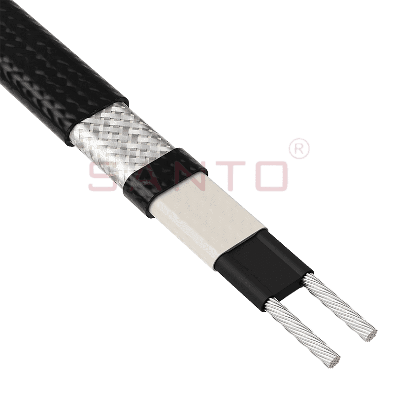
The SANTO UFA range of self-regulating heating cables is mainly used for frost protection of pipes and vessels but can also be used to maintain processes up to 65°C. These heating cables are available...
See Details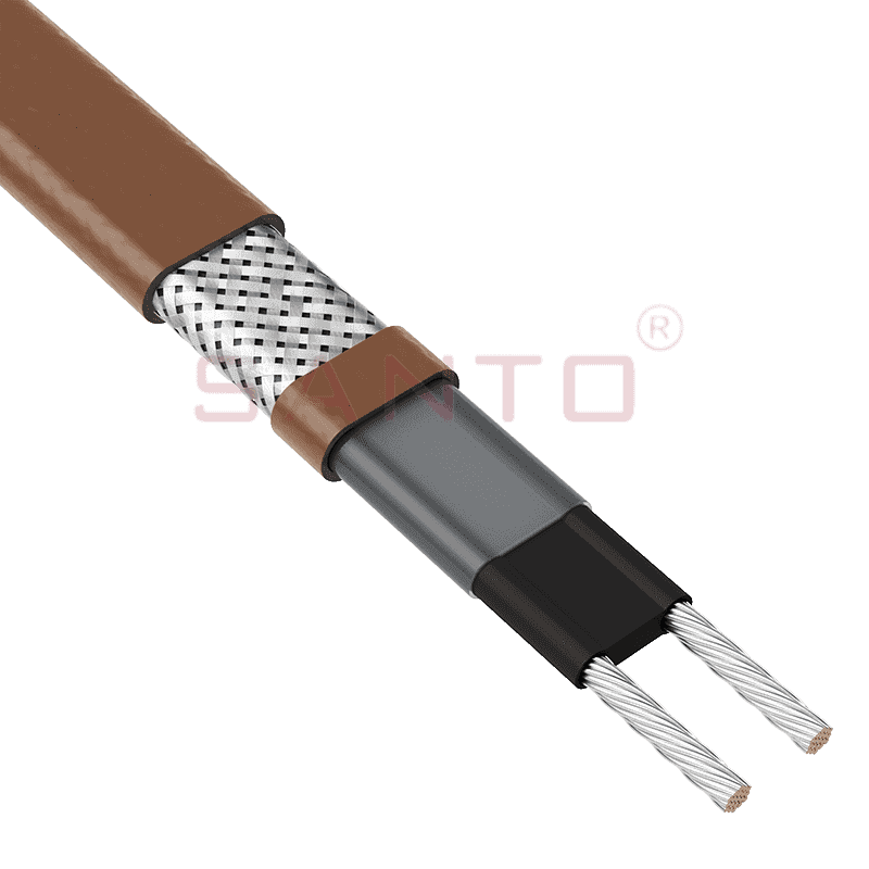
The SANTO UFB range of self-regulating heating cables is mainly used for frost protection of pipes and vessels requiring a higher power output than the UFA heating cables can supply. They can also be ...
See Details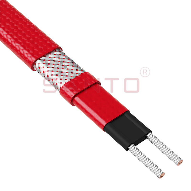
The SANTO UFC range of self-regulating heating cables is used for frost protection of pipes and vessels that require steam cleaning. They can also be used to maintain processes up to 121°C. These heat...
See Details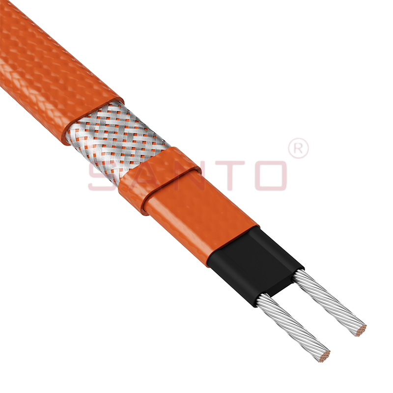
The SANTO UFO range of self-regulating heating cables is mainly used for frost protection of pipes and vessels that require steam cleaning . They can also be used to maintain processes up to 150°C. Th...
See Details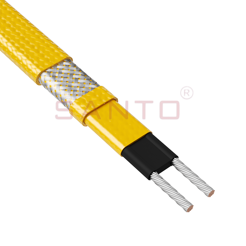
The SANTO UFD series of self-regulating heating cables are mainly used for freeze protection of pipes and vessels, but can also be used to maintain processes up to 200°C. These heating cables are avai...
See Details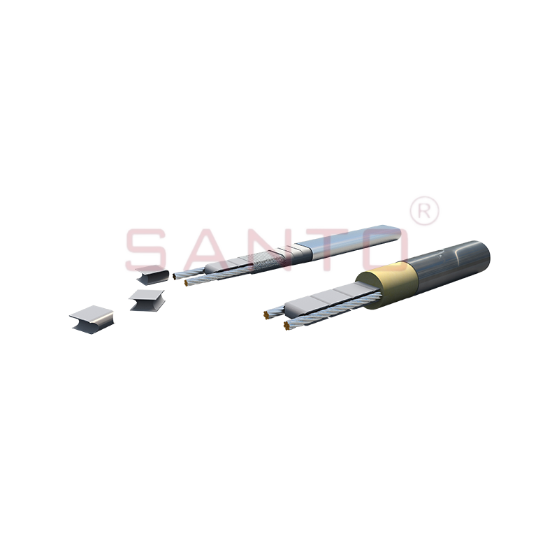
SANTO UFY heating wire is suitable for applications that maintain process temperatures up to 260 ℃ and can be steam blown; The self-regulating and parallel circuit heating wires of the UFY series are ...
See Details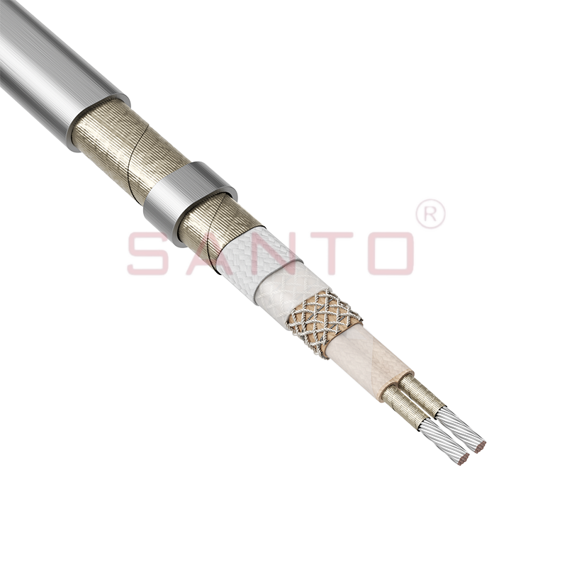
The SANTO UFM series self-regulating heating cables are mainly used for freeze protection of pipes and vessels, but can also be used to maintain processes up to 400°C. These heating cables are availab...
See Details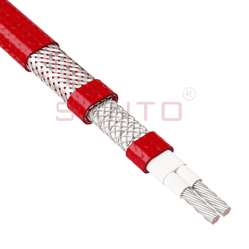
The SANTO ACC range of power-limiting heating cables is mainly used for temperature maintenance of processes and offers the advantage of a high power output at high temperatures which can reduce the n...
See Details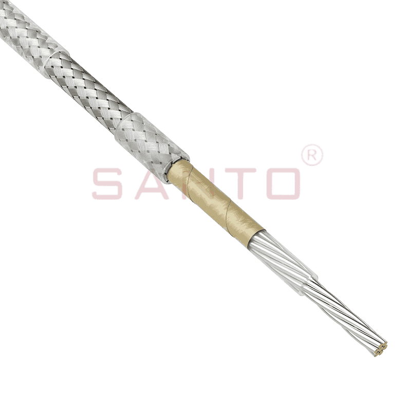
The stranded high temperature conductor is nickel plated to ensure a long life at elevated temperatures in corrosive environments. It is electrically isolated using an innovative sandwich construction...
See Details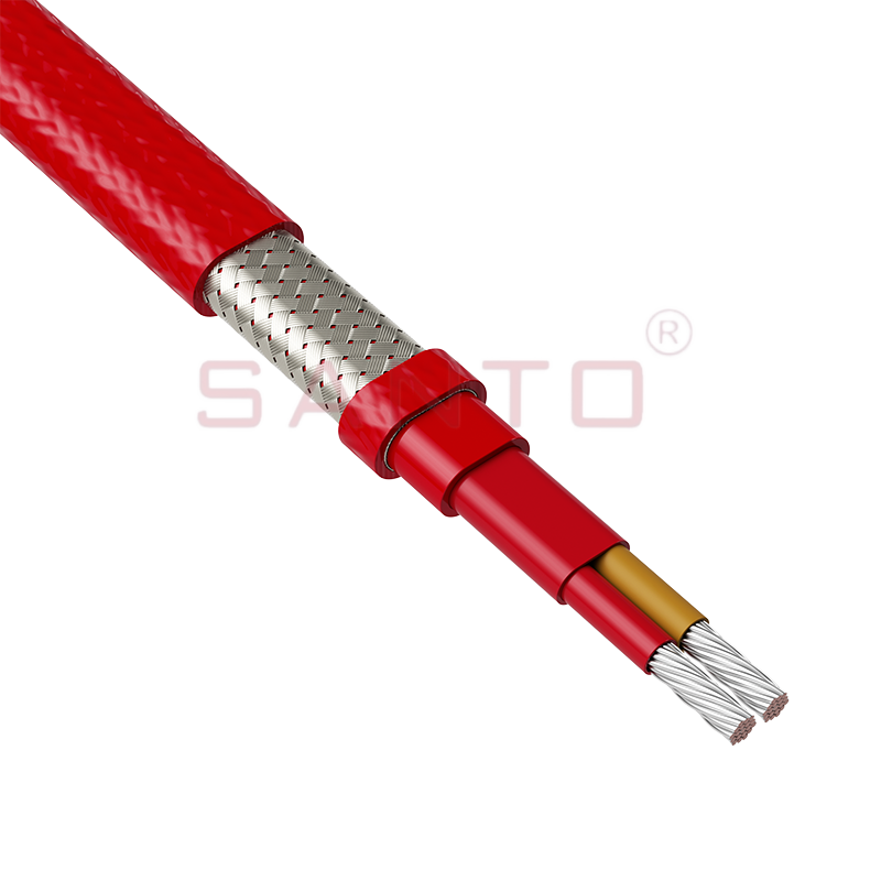
The stranded high temperature conductor is nickel plated to ensure a long life at elevated temperatures in corrosive environments. It is electrically isolated using an innovative sandwich construction...
See Details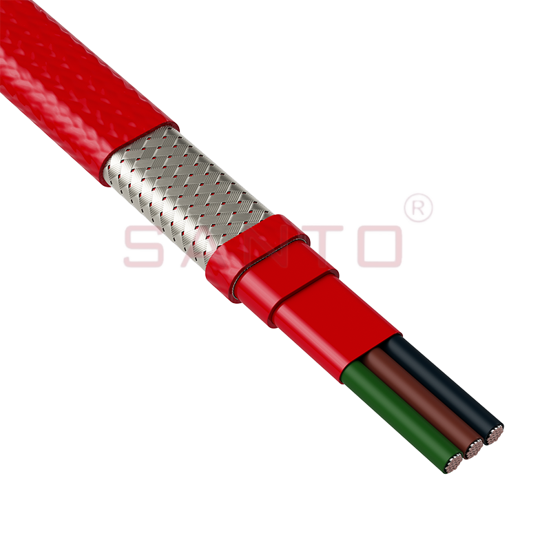
The stranded high temperature conductor is nickel plated to ensure a long life at elevated temperatures in corrosive environments. It is electrically isolated using an innovative sandwich construction...
See Details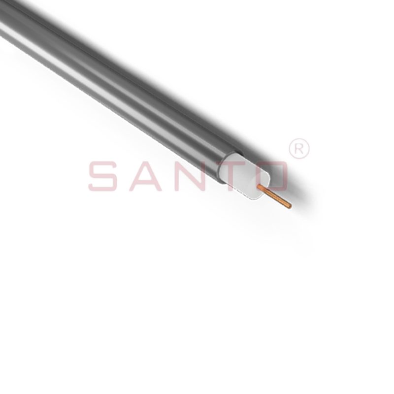
SANTO HAx mineral insulated (MI) Alloy 825 series heating cables are suitable for use in hazardous areas. They have been designed for use in freeze protection and temperature maintenance applications ...
See Details
Santo electric heating strips are widely used in key industries in China.

