 English
  English
 русский
 日本語
日本語 Español
 中文简体
中文简体
The SANTO UFA range of self-regulating heating cables is mainly used for frost protection of pipes and vessels but can also be used to maintain processes up to 65°C. These heating cables are available...
See Details
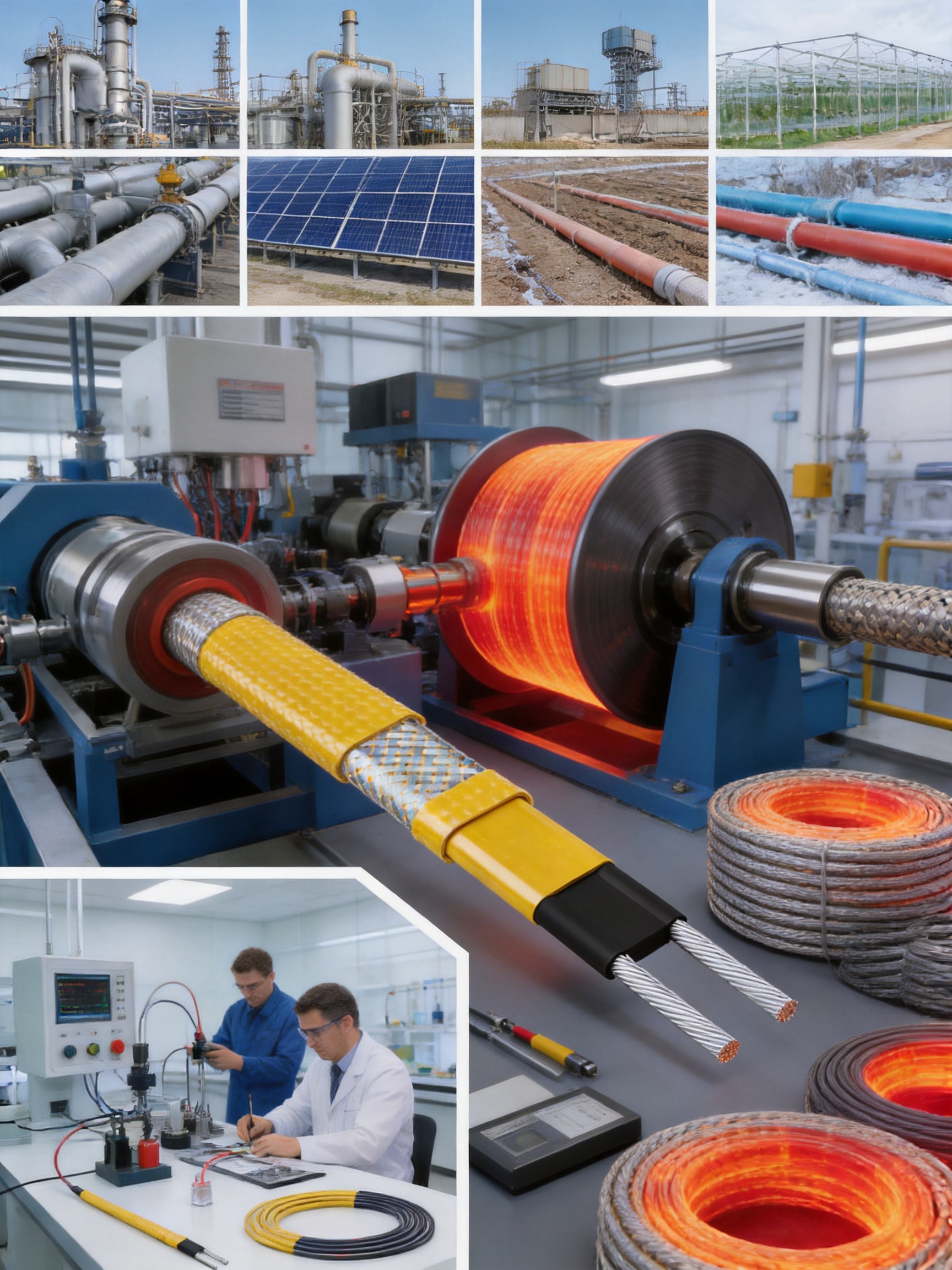
Self-regulating heating cables are widely used to protect pipes, vessels, tanks, valves, instruments, and process lines from freezing and to maintain required operating temperatures. Among the solutions available for industrial heat tracing, the SANTO UFD series is designed to combine automatic heat output adjustment, chemical-resistant construction, hazardous-area suitability, and high-temperature operating capability in one practical system.
The UFD series belongs to the category of self-regulating heating cables. Its main application is freeze protection, but the cable can also be used for process temperature maintenance up to 200°C when the installation is correctly designed and operated within the product’s approved limits. Two outer sheath options are available. The polyolefin version, identified by the -CR designation, is intended for locations exposed to mild inorganic solutions. The fluoropolymer version, identified by the -CT designation, provides a higher level of chemical resistance for more demanding industrial environments.
This combination of automatic output control and material flexibility makes the cable suitable for a broad range of applications in petroleum, chemical processing, gas, construction, solar energy, electric heating, geothermal cultivation, and related industries. It can be used to reduce the risk of frozen water lines, preserve process fluid flow, protect safety systems, and stabilize temperatures in equipment exposed to low ambient conditions.
Content
A self-regulating heating cable is designed to adjust its heat output in response to the temperature around the cable. When the surrounding temperature falls, the cable produces more heat. When the surrounding temperature rises, the cable produces less heat. This operating behavior is the central distinction between a self-regulating cable and many conventional constant-wattage heating products.
The self-regulating effect is produced by a conductive polymer heating core located between parallel conductors. The core changes its electrical characteristics as its temperature changes. At lower temperatures, the material allows greater current flow and generates increased heat. As the temperature rises, the material becomes more resistive, reducing current flow and heat output.
This response is distributed along the length of the cable. As a result, different sections can react independently to their local thermal conditions. A cold section near an exposed valve may produce more heat than a warmer section running across an insulated pipe. This localized response is particularly useful on complex pipe systems where the heat loss is not uniform.
Self-regulation does not mean that the cable can be installed without engineering assessment. Heat loss, insulation thickness, ambient temperature, cable spacing, power supply, circuit protection, maximum exposure temperature, and installation conditions must all be considered. However, the automatic output response can make the system more tolerant of local temperature differences and reduce the risk associated with excessive heat generation in warmer sections.
The SANTO UFD series is primarily intended for freeze protection of pipes and vessels. Freezing can cause serious operational and financial consequences. Water and other liquids expand as they freeze, potentially damaging pipes, fittings, pumps, instruments, fire-protection lines, and storage equipment. In industrial systems, a frozen line may also interrupt production or prevent a safety system from functioning when needed.
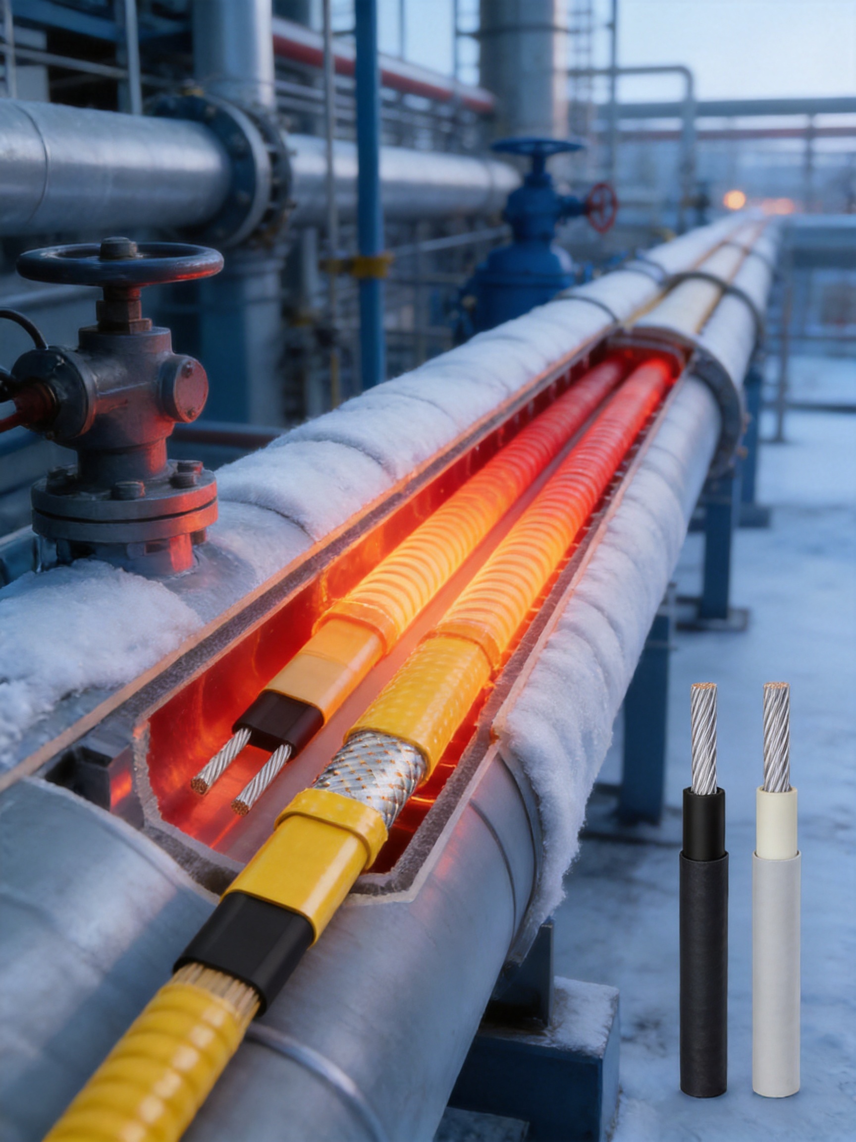
By applying controlled heat to the outer surface of a pipe or vessel, the cable helps compensate for heat lost to the surrounding environment. When properly selected and installed beneath suitable thermal insulation, it can help maintain the contents above their freezing point.
The same product family can also be used for process temperature maintenance up to 200°C. This makes it relevant to systems where the purpose is not merely to prevent freezing but to preserve a minimum operating temperature. Examples may include maintaining the flowability of viscous liquids, reducing condensation, preventing crystallization, or keeping process lines within a specified temperature range.
The stated 200°C process capability should be interpreted as a design limit that must be evaluated together with the cable construction, exposure conditions, control method, and installation arrangement. The actual permitted temperature may depend on whether the cable is energized, de-energized, exposed, insulated, or installed in a hazardous area. A qualified engineer should confirm the applicable rating for each project.
The UFD range is available with two different outer sheath materials. Selecting the appropriate sheath is important because the outer jacket is the cable’s primary barrier against the surrounding environment.
The -CR version uses a polyolefin outer sheath. It is suitable for areas where the cable is exposed only to mild inorganic solutions. Polyolefin materials are commonly selected for applications requiring a practical balance of flexibility, electrical insulation, weather resistance, and general-purpose chemical performance.
The -CT version uses a fluoropolymer outer sheath. Fluoropolymers are known for high chemical resistance and are therefore appropriate for more aggressive industrial environments. This option can be considered where contact with process chemicals, cleaning agents, solvents, or other corrosive substances creates a greater demand on the cable jacket.
The sheath selection should be based on the actual chemical exposure rather than on general assumptions. The chemical concentration, operating temperature, exposure duration, cleaning procedure, mechanical conditions, and possible combinations of chemicals can all influence material performance. A chemical compatibility review is recommended before final product selection.
| Product feature | -CR version | -CT version | Typical selection consideration |
|---|---|---|---|
| Outer sheath material | Polyolefin | Fluoropolymer | Select according to environmental and chemical exposure |
| Primary environmental position | Mild inorganic solutions | More demanding chemical environments | Review concentration, temperature, and contact duration |
| Main application | Freeze protection and temperature maintenance | Freeze protection and temperature maintenance | Both versions require correct design and installation |
| Process capability | Up to 200°C within applicable design conditions | Up to 200°C within applicable design conditions | Confirm the complete system rating before use |
| Hazardous-area suitability | Approved for specified zones and T2 classification | Approved for specified zones and T2 classification | Follow the relevant installation and certification requirements |
The most important advantage of a self-regulating heating cable is its ability to respond to changing local temperatures. A constant-wattage cable normally produces a relatively fixed amount of heat per unit length whenever energized. If one section of the pipe is colder than another, the constant-wattage system does not automatically redistribute output according to the local need.
By contrast, a self-regulating cable can increase output in colder areas and reduce output in warmer areas. This can support more consistent temperature protection along irregular pipe routes. The behavior is especially useful around supports, valves, flanges, dead legs, and exposed fittings, where heat loss may differ from that of a straight pipe section.
Another advantage is the possibility of cutting the cable to the required length in the field, subject to the manufacturer’s instructions and approved termination method. This can reduce the need to stock many fixed-length assemblies and can simplify adaptation to different pipe runs. The installer must still respect minimum circuit lengths, maximum circuit lengths, termination requirements, power limitations, and relevant certification conditions.
Self-regulating technology can also reduce the risk of localized overheating compared with some fixed-output systems. When a section becomes warmer, its output decreases. This does not eliminate all thermal risks, because the surrounding process, insulation, control equipment, and cable installation still affect the final temperature. Nevertheless, the inherent output response is a valuable safety and performance feature.
Compared with temporary heating methods, a permanently installed heat-tracing system provides a more organized and repeatable solution. Portable heaters, heat lamps, or improvised electrical devices may be difficult to monitor and may create access, fire, or weather-related concerns. A properly designed cable system can be integrated with insulation, electrical protection, temperature control, inspection procedures, and maintenance documentation.
Energy use depends on many variables, including ambient temperature, pipe size, insulation quality, cable output, operating time, and control strategy. A self-regulating cable does not consume the same level of energy along every section under all conditions. Its output naturally responds to temperature changes, which can help avoid unnecessary heating in areas that are already warmer.
For larger systems, this behavior can support more efficient operation when combined with appropriate controls and insulation. Temperature controllers, ambient sensors, line sensors, contactors, circuit monitoring, and residual-current protection may be incorporated according to the project design. A well-insulated pipe reduces the heat required from the cable and improves system stability.
Energy efficiency should not be judged only by cable output. Poor insulation, incorrectly positioned sensors, excessive cable spacing, damaged jackets, or unnecessary continuous operation can reduce overall efficiency. The strongest results are obtained when the cable, insulation, controls, and maintenance program are designed as one integrated system.
The UFD products are approved for use in hazardous areas classified as Zone 1 and Zone 2 for gas atmospheres and Zone 21 and Zone 22 for dust atmospheres. They have an absolute temperature rating of T2 in accordance with the European standard EN 60079-30-1, as stated in the supplied product information.
Hazardous-area approval is a major consideration in industries such as petroleum, chemical manufacturing, natural gas, fuel storage, solvent processing, and other facilities where flammable gases, vapors, or combustible dust may be present. Electrical heating equipment installed in these locations must be selected and installed in a way that limits ignition risks.
Zone 1 generally describes an area in which an explosive gas atmosphere is likely to occur during normal operation occasionally. Zone 2 generally describes an area in which such an atmosphere is not likely to occur during normal operation but may exist for a short period if it does occur. Zone 21 and Zone 22 apply similar concepts to combustible dust atmospheres.
The T2 temperature classification indicates that the maximum surface temperature must remain within the limit associated with that class under the relevant conditions. The classification is not a substitute for project-specific engineering. The installer must evaluate the process temperature, cable surface temperature, surrounding material, dust layer conditions, electrical equipment, glands, junction boxes, end seals, and control system.
Certification markings, installation instructions, permitted accessories, circuit protection, and inspection requirements should be checked before installation. Every part of the heat-tracing circuit must be suitable for the classified area. A certified heating cable connected to unsuitable accessories or installed with incorrect termination methods may not provide a compliant system.
Before a hazardous-area installation begins, the engineering team should prepare a line list and area classification drawing. The line list should identify pipe size, length, material, process temperature, minimum ambient temperature, insulation type, insulation thickness, valves, flanges, supports, instruments, and required maintenance temperature.
The design should also identify the required cable length, circuit load, operating voltage, circuit protection, control method, and maximum sheath temperature. Where dust may accumulate, the design should consider the effect of dust layers on heat dissipation. All cable spacing and installation details should follow the approved documentation.
Mechanical protection is equally important. The cable should not be crushed, sharply bent, stretched, or installed over edges that could damage the sheath. Penetrations through insulation cladding should be sealed appropriately. The system should be inspected after installation and periodically during service.
Petroleum facilities often contain outdoor piping, valves, tanks, loading systems, instrument lines, and fire-protection equipment that may be exposed to low temperatures. A self-regulating heating cable can be used to help maintain flow and protect water-based or process-related lines from freezing.
In these facilities, hazardous-area suitability and chemical resistance are critical. The fluoropolymer -CT version may be considered where contact with hydrocarbons, cleaning fluids, or aggressive chemicals creates higher material demands. The final selection must be based on the actual exposure data.
Chemical plants contain many fluids with different freezing points, viscosities, and temperature requirements. Some lines require only freeze protection, while others require a controlled maintenance temperature to prevent crystallization or preserve flowability.
The UFD series provides a choice of sheath materials that can support different environmental conditions. The -CR version may be suitable for mild inorganic exposure, while the -CT version can provide a higher level of chemical resistance. Engineers should also evaluate whether the process fluid, insulation, pipe material, and heat-tracing cable are compatible with one another.
Gas facilities may use heating cables on pressure-sensing lines, drain lines, instrument enclosures, valves, and outdoor utility piping. Moisture and freezing can interfere with instruments and control components. Heat tracing can help maintain reliable operation during cold-weather conditions.
Because gas facilities may include classified areas, the product’s hazardous-area approval is particularly relevant. Installation should be carried out by qualified personnel who understand both heat tracing and explosion-protection requirements.
In commercial, industrial, and infrastructure projects, self-regulating cables can protect water pipes, roof drains, gutters, ramps, loading areas, and exposed service lines. The same technology can be integrated with building insulation and automatic controls.
For building services, the cable is often valued for its adaptability. Pipe routes may include numerous fittings and irregular sections. The cable can be selected and arranged to follow the actual route, provided the installation complies with the product instructions.
Solar installations may include exposed water lines, fluid circuits, storage tanks, equipment cabinets, and other components that require temperature protection. In cold climates, a heating cable may help reduce freezing risk in water-based systems and support reliable operation during winter conditions.
The cable must be selected for exposure to sunlight, moisture, temperature cycling, and the specific fluid used in the system. Where chemical additives are present, the outer sheath should be evaluated for compatibility.
Geothermal cultivation, greenhouse systems, agricultural water supply, and temperature-controlled growing facilities may require freeze protection for pipes and vessels. A self-regulating cable can help protect irrigation lines, nutrient solution systems, tanks, and external plumbing.
These applications may involve moisture, fertilizers, cleaning chemicals, ultraviolet exposure, and frequent maintenance activity. The choice between polyolefin and fluoropolymer sheathing should be based on the actual environmental conditions rather than on application category alone.
The manufacturer behind the UFD series is Santo Thermal Control Technology Co., Ltd., a Chinese producer of electric heating and thermal-control products. The company is located in Jiangsu Province, an area recognized for electric heating belt manufacturing. Its reported capabilities cover research, design, production, manufacturing, technical guidance, quality management, and sales.
The company’s product portfolio includes automatic temperature-control heating belts, self-limiting heating belts, heat-tracing belts, constant-power heating cables, glass-fiber heating belts, mineral-insulated cables, silicone rubber heating systems, snow-melting cables, LCD-tracked heaters, electric hot wires, and related accessories.
This broad portfolio can be advantageous to industrial buyers because different areas of one project may require different heating technologies. A supplier with experience in several cable categories may be better positioned to recommend a system architecture instead of treating every application as a standard cable sale.
According to the supplied company information, the organization cooperates in product research with Harvard University in the United States and has invested in the development of new heating technologies. The company’s reported development history includes work on a self-limiting temperature nano far-infrared heater for high-temperature pipeline heating and tracing, as well as the development of a carbon-fiber parallel heating cable.
Research capability is important in heat tracing because product performance depends on the interaction of conductive materials, polymer behavior, insulation, metallic components, sheath compounds, connection technology, and environmental exposure. Improvements in any one of these areas can influence flexibility, durability, heat output, temperature control, and installation performance.
Product development also supports customization. Industrial users may require different cable lengths, sheath materials, power characteristics, connection accessories, circuit arrangements, or packaging formats. A manufacturer with in-house technical knowledge can more readily evaluate such requirements.
The company reports that an irradiation center was established in 2013 and that a product simulation testing laboratory was planned as part of its expanded factory development. Irradiation and simulation testing can be relevant to polymer processing, cable durability, product verification, and evaluation under representative operating conditions, depending on the specific test methods used.
Testing should cover more than electrical continuity. A professional heating-cable quality program may include conductor resistance, insulation resistance, dielectric strength, sheath integrity, dimensional inspection, power-output verification, temperature exposure, bending performance, aging behavior, and mechanical inspection.
For products intended for hazardous areas, certification and production controls are particularly important. The manufacturer and user should maintain traceability for raw materials, production batches, inspection records, certification documentation, and final product identification.
The company states that it has passed ISO9001 quality system certification and that its products have obtained national CCC certification. These systems and certifications can provide evidence of structured quality management, although buyers should verify the current validity, scope, certificate numbers, and product applicability for a specific purchase.
Quality assurance is most effective when it is integrated into every production stage. Incoming materials should be inspected before use. Conductors, polymer compounds, metallic braids, outer sheath materials, and connection components should be controlled according to defined specifications.
During manufacturing, process parameters should be monitored and recorded. Extrusion temperature, line speed, dimensional tolerances, conductor placement, braiding, marking, and winding conditions can influence final cable performance. Finished products should undergo electrical and visual inspection before packaging.
For export projects, documentation is also part of quality. Product datasheets, installation instructions, test records, certificates, packaging lists, and technical declarations should correspond to the actual product supplied. Clear documentation reduces installation errors and supports future maintenance.
Correct installation is essential to the performance of any heating cable. Before work begins, the installer should confirm the cable type, voltage, circuit length, sheath material, approved accessories, area classification, and design temperature. The pipe or vessel surface should be clean, dry, and free from sharp projections that could damage the cable.
The heating cable is usually positioned along the pipe and secured using approved fixing materials. Metal bands, suitable tapes, or other specified methods may be used depending on the cable design. Materials that could cut, abrade, chemically attack, or excessively compress the sheath should not be used.
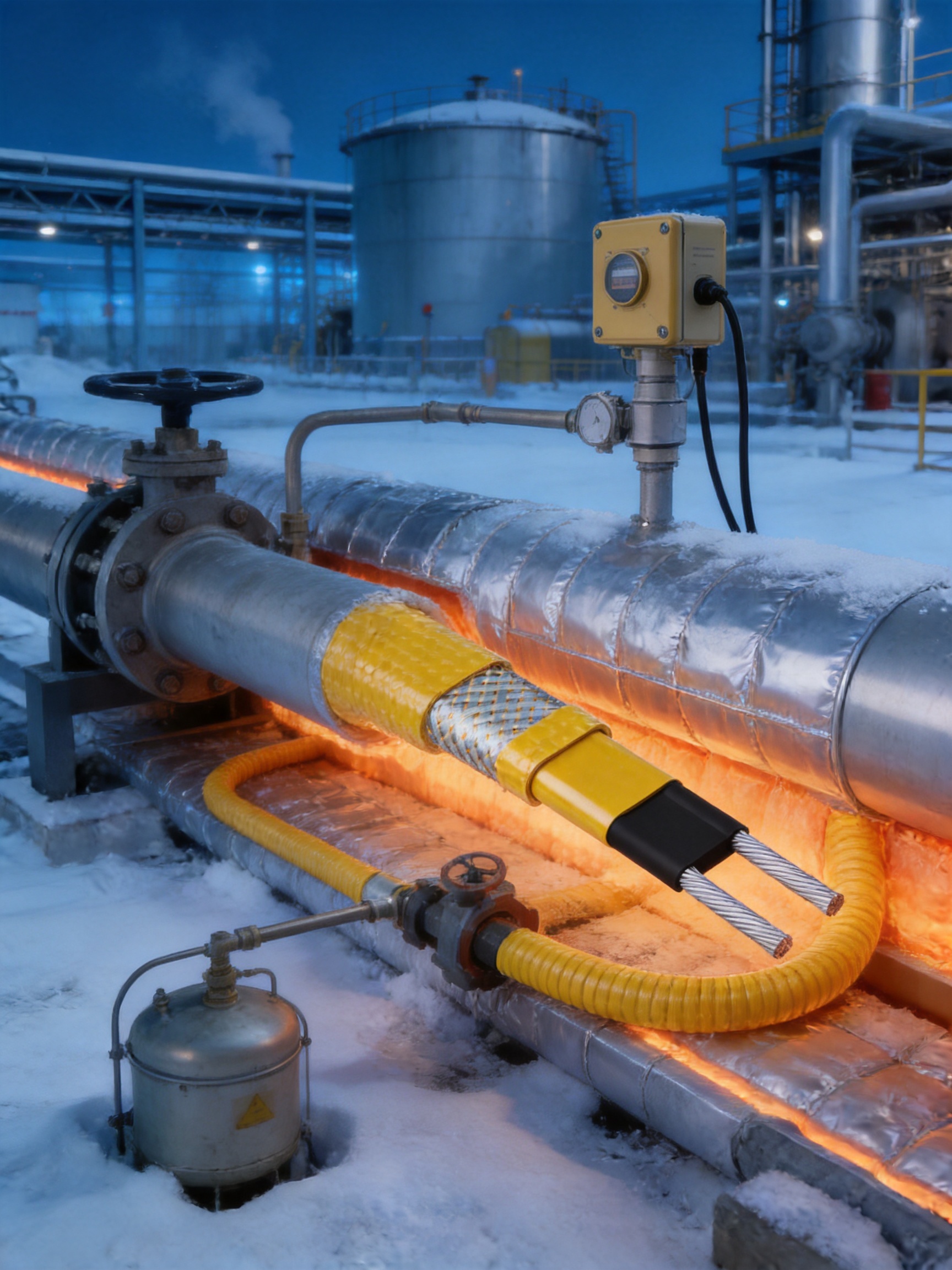
On small pipes, one cable run may be sufficient. Larger pipes or high-heat-loss systems may require multiple runs or a calculated spiral arrangement. Valves, flanges, supports, pumps, strainers, and instruments often require additional cable length because they lose more heat than the straight pipe. These components should be included in the heat-loss calculation.
The cable should be installed with smooth bends and without kinks. The minimum bending radius specified by the manufacturer must be respected. The cable should not be pulled by the outer sheath or used as a mechanical support. It should not be installed under excessive tension.
After the cable is installed, thermal insulation and protective cladding should be fitted without crushing or displacing the cable. Warning labels should identify the presence of electric heat tracing beneath the insulation. The installation should allow access to junction boxes, controllers, and test points where maintenance is required.
Each circuit should be designed with suitable overcurrent protection and, where required, residual-current or ground-fault protection. The electrical design should account for starting current, steady-state load, ambient temperature, grouping, cable length, and the characteristics of the power supply.
Although self-regulating cables reduce output as their temperature rises, they should not automatically be connected without considering control requirements. A thermostat, ambient controller, line-sensing controller, or process control system may be appropriate depending on the application. In hazardous areas, the control equipment and switching method must also comply with the applicable classification requirements.
Temperature sensors should be located where they can measure a representative condition. A sensor mounted too close to the cable may respond to cable heat rather than process temperature. A sensor placed in a warm indoor area may fail to detect freezing conditions at an exposed outdoor valve.
Thermal insulation is a fundamental part of a heat-tracing system. The cable supplies heat, but the insulation determines how effectively that heat is retained. Insulation thickness should be selected based on pipe size, ambient temperature, required maintenance temperature, insulation material, wind exposure, and other heat-loss factors.
Moisture in insulation can significantly reduce thermal performance. Water ingress may also create corrosion, electrical leakage, and mechanical damage. The insulation and external cladding should therefore be installed and sealed according to the project specification.
Outdoor installations may require protection from ultraviolet radiation, rain, snow, impact, chemicals, and animals. The selected outer sheath and protective covering should match the environment. Areas subject to frequent maintenance or foot traffic may require additional mechanical protection.
A reliable heat-tracing design starts with a complete equipment and piping survey. Each circuit should be identified by tag number and associated with a line or vessel. The survey should record length, diameter, material, contents, minimum ambient temperature, required temperature, insulation details, fittings, and location.
The next step is to calculate heat loss. Heat loss depends on the temperature difference between the protected object and the surrounding air, the thermal conductivity and thickness of insulation, surface area, wind speed, and other environmental conditions. Fittings and equipment often need separate allowances.
The required cable output should then be compared with the calculated heat loss. The design should include a suitable margin without creating an unnecessary thermal load. Cable selection must also account for operating voltage, circuit length, maximum exposure temperature, hazardous-area requirements, chemical exposure, and available accessories.
For process temperature maintenance, the designer should consider the normal process temperature and possible upset conditions. If the pipe can be exposed to a temperature above the cable’s permitted rating, the cable may need to be de-energized, protected, or replaced by a different heating technology.
For freeze protection, the designer should identify the lowest expected ambient temperature and the minimum acceptable process temperature. The system should be able to maintain that temperature during the worst credible weather conditions, including wind and periods when the process is shut down.
One of the practical strengths of working with a specialized heating manufacturer is access to related accessories and technical support. A heat-tracing system is not only a cable. It may include power connection kits, end seals, splice kits, tee connections, thermostats, sensors, junction boxes, mounting materials, warning labels, electrical protection, and insulation accessories.
Matching components can reduce compatibility problems. The connection method must be suitable for the cable construction, voltage, temperature, and hazardous-area classification. A reliable supplier should be able to provide product information for the complete assembly and explain which accessories are approved for the selected cable.
The company’s reported experience includes more than 35 years in the industry, annual output of more than 10,000 units or product sets, more than 2,000 distributors, and business covering more than 85 areas. These figures indicate an established commercial network, although buyers should request current company records and project references when evaluating a specific contract.
The company also reports international market participation, explosion-proof certification, EAC Eurasian Union certification, and the establishment of a Russia factory in 2023. International experience can help a supplier understand export packaging, regional standards, documentation, and customer support requirements.
Industrial heat-tracing projects are often different from one another. A standard cable may be suitable for many applications, but customers may also need customized lengths, marking, packaging, power configurations, sheath choices, temperature ratings, or accessory combinations.
OEM and ODM capability can be useful when a distributor wants private labeling, when an engineering company requires a project-specific cable assembly, or when an equipment manufacturer wants to integrate heat tracing into a larger product. Customization should be controlled through technical drawings, approved samples, test requirements, and written specifications.
Before placing a customized order, the buyer should provide the operating voltage, required circuit length, minimum and maximum temperatures, environmental exposure, chemical information, area classification, installation method, and applicable standards. The manufacturer can then review whether the requested configuration is technically feasible and compliant.
Customization should never be used to bypass certification limitations. If a cable is intended for a hazardous area, any change to the construction, sheath, termination, power rating, or accessory arrangement may affect certification. The manufacturer should confirm the certification status of the final configuration.
Regular inspection helps preserve system reliability. Before winter or before a critical operating period, maintenance personnel should inspect power connections, junction boxes, insulation cladding, labels, cable routing, and visible sections of the heating circuit.
Electrical tests may include insulation resistance and continuity checks. The measured values should be compared with commissioning records and previous maintenance data. A sudden reduction in insulation resistance may indicate moisture ingress, mechanical damage, chemical attack, or a termination problem.
Insulation should be checked for wet areas, gaps, compression, missing sections, and damaged weatherproofing. Even a correctly functioning cable may not maintain the required temperature if the insulation has deteriorated.
Temperature controllers and sensors should be calibrated or functionally checked at appropriate intervals. A failed sensor or incorrectly configured controller can cause a circuit to remain off during freezing weather or operate unnecessarily during warm conditions.
In hazardous areas, inspection should follow the applicable explosion-protection procedures. Unauthorized modifications, non-certified replacement parts, damaged glands, and open enclosures can compromise the safety of the entire installation.
One common error is choosing the cable solely according to pipe length. Pipe diameter, insulation, fittings, ambient temperature, and required temperature are equally important. A long pipe with excellent insulation may require less heating than a short pipe with poor insulation and several exposed valves.
Another error is selecting the outer sheath without checking chemical exposure. The -CR polyolefin version is intended for mild inorganic solutions, while the -CT fluoropolymer version provides higher chemical resistance. If the environment is uncertain, the buyer should collect chemical safety data and request a compatibility review.
Ignoring maximum exposure temperature is also a serious mistake. The cable may be suitable for a process temperature during operation but unsuitable during steam cleaning, hot-water flushing, sterilization, or emergency conditions. All operating and non-operating temperature scenarios should be reviewed.
Installers sometimes damage the cable by crossing it over itself, placing it beneath sharp metal edges, pulling it too tightly, or crushing it under insulation cladding. These practices can reduce service life and may create electrical faults.
A further error is failing to trace and document each circuit. Every cable should be identified at the power connection and end termination. Drawings, test values, circuit lengths, and inspection results should be retained for future maintenance.
Constant-wattage heating cables can provide a stable and predictable output per unit length, which may be useful for certain carefully controlled applications. However, they can require more precise spacing and temperature control because output does not automatically reduce in warmer sections.
Mineral-insulated cables can provide excellent resistance to high temperatures and mechanical stress, but they may require specialized installation and termination practices. They are often selected for demanding high-temperature applications where the flexibility and self-regulating response of a polymer-based cable are not the primary requirements.
Silicone rubber heating products are useful where flexibility and specialized temperature performance are required. Glass-fiber heating belts can be suitable for particular surfaces and equipment. Snow-melting cables are designed for outdoor deicing and may have different construction and installation requirements.
The UFD series occupies a practical position where automatic heat-output response, freeze protection, process maintenance up to 200°C, sheath selection, and hazardous-area suitability are important. Its advantage is not that it replaces every other heating technology, but that it offers a balanced solution for a wide range of pipe and vessel applications.
For the best result, the technology should be selected according to the application rather than by product category alone. A specialized supplier can help compare self-regulating, constant-power, mineral-insulated, silicone, and other heating solutions based on temperature, environment, mechanical conditions, control requirements, and certification.
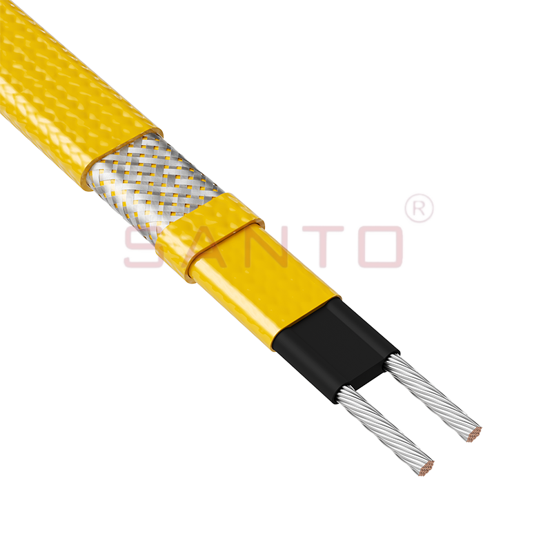
SANTO UFD
Heating cables operate in environments where electrical, thermal, mechanical, and chemical stresses occur simultaneously. The quality of the conductive core affects heat output. The conductor and insulation affect electrical safety. The outer sheath affects chemical and environmental resistance. The connection accessories determine whether the circuit remains sealed and reliable over time.
Manufacturing consistency is therefore essential. Small variations in core dimensions or material composition can influence resistance and output. Poorly controlled extrusion can create thin spots or voids in the insulation. Inconsistent braiding or grounding components can affect protection and termination. Inadequate marking can make maintenance and circuit identification more difficult.
A mature manufacturer should control raw materials, process conditions, product testing, packaging, and traceability. The company’s reported history of quality-system certification, product development, specialized production, and international distribution provides a foundation for serving industrial customers. Buyers should complement that foundation with project-specific documentation and acceptance testing.
Factory inspection may include review of production equipment, laboratory facilities, calibration records, quality procedures, nonconformance handling, operator training, and sample test reports. For large projects, third-party inspection or witnessed testing may also be considered.
When purchasing the UFD series or a comparable self-regulating heating cable, the buyer should prepare a technical inquiry rather than requesting price based only on a product name. The inquiry should describe the application and include enough data for correct selection.
Important information includes the pipe or vessel material, size, length, contents, freezing point, normal process temperature, required maintenance temperature, minimum ambient temperature, insulation type, insulation thickness, wind exposure, chemical environment, hazardous-area classification, supply voltage, control method, and required accessories.
The buyer should request a technical datasheet, installation instructions, certification documents, sheath material information, electrical ratings, allowable temperatures, recommended accessories, test documentation, and packaging details. If the product is being exported, the buyer should also confirm labeling, language requirements, customs documentation, and regional electrical standards.
For a major project, a sample installation can be valuable. A pilot section allows the engineering team to check routing, termination, sensor placement, insulation installation, and temperature performance before the full system is completed.
It is also advisable to establish a spare-parts policy. Spare cable, end seals, connection kits, labels, controllers, and sensors may be needed during construction or future maintenance. The spare-parts list should be based on the number and type of installed circuits.
The main purpose is freeze protection for pipes and vessels. It can also be used for process temperature maintenance up to 200°C within the applicable product and installation conditions.
The conductive polymer heating core changes its electrical behavior as its temperature changes. Colder sections produce more heat, while warmer sections produce less heat. This response occurs along the cable according to local temperature conditions.
The -CR version has a polyolefin outer sheath and is suitable for exposure to mild inorganic solutions. The -CT version has a fluoropolymer outer sheath and provides higher chemical resistance. The actual selection should be based on the chemical, temperature, and mechanical conditions of the installation.
The supplied product information states that the products are approved for Zone 1 and Zone 2 gas atmospheres and Zone 21 and Zone 22 dust atmospheres, with an absolute temperature rating of T2 according to EN 60079-30-1. The complete installation must use suitable certified components and follow the relevant requirements.
No. Approval does not replace engineering controls. The process temperature, surface temperature, dust conditions, circuit protection, sensors, controllers, accessories, and installation method must all be evaluated.
Yes. The product information states that the series can maintain processes up to 200°C. The designer must confirm that the specific application, exposure temperature, insulation system, control method, and area classification remain within the approved limits.
Insulation reduces heat loss from the pipe or vessel. Without suitable insulation, the cable may not be able to maintain the required temperature efficiently. Moisture-resistant installation and protective cladding are also important for long-term performance.
No. Different pipes may require different cable lengths, power levels, sheath materials, control methods, or heating technologies. Selection should consider the pipe size, process, ambient temperature, insulation, chemical environment, and hazardous-area classification.
The installer should check the product type, sheath material, cable length, voltage, temperature ratings, approved accessories, circuit protection, area classification, routing plan, pipe condition, and insulation specification. The cable should be inspected for damage before it is installed.
Repairs should only be made using approved procedures and compatible accessories. In hazardous areas, unauthorized repairs or modifications may invalidate certification. The manufacturer or qualified technical personnel should be consulted before repairing a damaged circuit.
Potential industries include petroleum, chemical processing, gas, construction, solar energy, geothermal cultivation, agriculture, utilities, and general industrial manufacturing. The product is particularly relevant where pipes or vessels require freeze protection or controlled temperature maintenance.
The company reports more than 35 years of industry experience, a broad electric-heating product portfolio, research and development activity, quality-system certification, international market experience, a distributor network, and production and testing infrastructure. Buyers should verify current certifications, technical scope, and project references for their specific requirements.
The SANTO UFD series provides a flexible approach to industrial heat tracing by combining self-regulating heat output with two outer sheath options, process maintenance capability up to 200°C, and stated suitability for specified hazardous areas. Its core value lies in adapting heat output to local temperature conditions while supporting applications that range from simple freeze protection to more demanding industrial temperature-maintenance duties.
The -CR polyolefin version offers a practical choice for environments involving mild inorganic solutions, while the -CT fluoropolymer version is intended for applications requiring higher chemical resistance. This material choice allows engineers to align the cable construction with the actual operating environment instead of relying on a single universal sheath.
The product’s performance depends on more than the cable itself. Accurate heat-loss calculations, suitable insulation, correct routing, certified accessories, electrical protection, temperature control, hazardous-area compliance, and regular inspection are all necessary for a dependable system.
The manufacturer’s reported experience in self-regulating, constant-power, silicone, glass-fiber, mineral-insulated, snow-melting, and other electric-heating technologies supports its ability to serve varied industrial requirements. Its stated research, manufacturing, quality-management, certification, and international distribution capabilities may also benefit customers seeking OEM, ODM, or project-specific supply.
For purchasers, the most effective approach is to provide complete application data and request a technically reviewed solution. When the product is correctly selected, installed, documented, and maintained, a self-regulating heating cable can help protect critical equipment, reduce freezing-related interruptions, support process stability, and improve the reliability of industrial operations.
1. EN 60079-30-1, Explosive atmospheres — Part 30-1: Electrical resistance trace heating — General and testing requirements.
2. International Electrotechnical Commission, standards and technical guidance relating to electrical equipment for explosive atmospheres.
3. Product information supplied for the SANTO UFD self-regulating heating cable series.
4. Manufacturer-provided information concerning electric heating cable production, research, quality management, certifications, and company development.
5. General engineering principles for electric heat tracing, thermal insulation, temperature control, and industrial freeze protection.
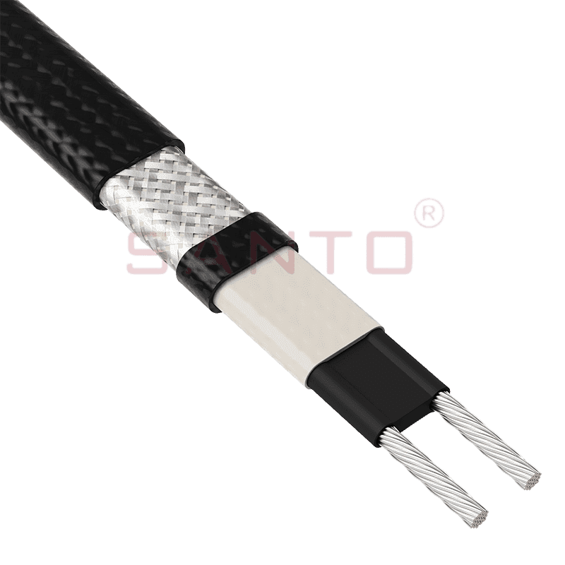
The SANTO UFA range of self-regulating heating cables is mainly used for frost protection of pipes and vessels but can also be used to maintain processes up to 65°C. These heating cables are available...
See Details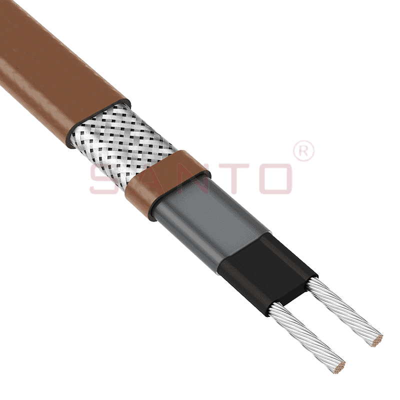
The SANTO UFB range of self-regulating heating cables is mainly used for frost protection of pipes and vessels requiring a higher power output than the UFA heating cables can supply. They can also be ...
See Details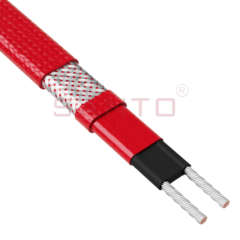
The SANTO UFC range of self-regulating heating cables is used for frost protection of pipes and vessels that require steam cleaning. They can also be used to maintain processes up to 121°C. These heat...
See Details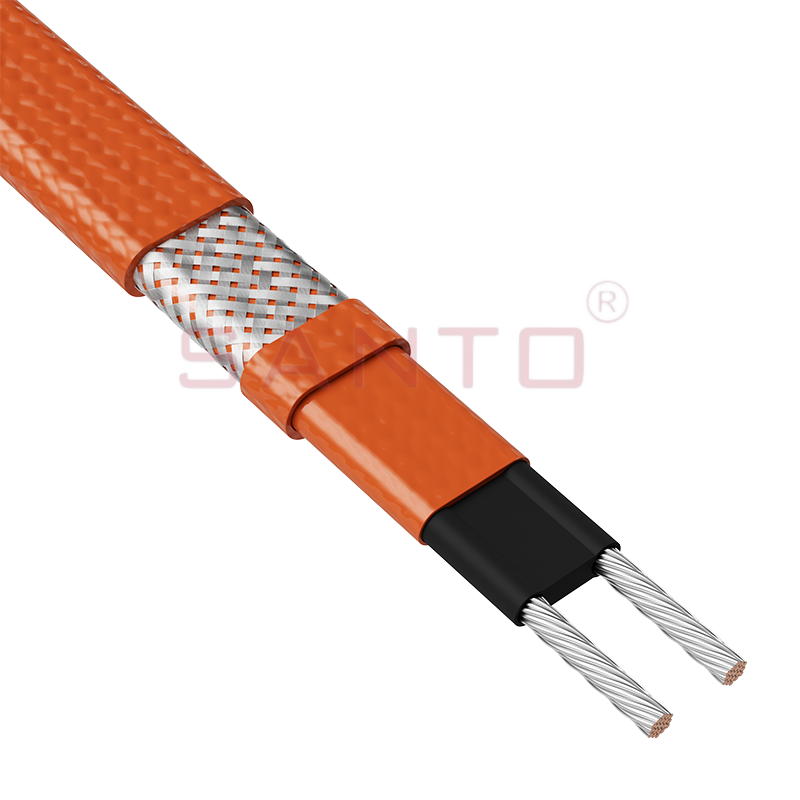
The SANTO UFO range of self-regulating heating cables is mainly used for frost protection of pipes and vessels that require steam cleaning . They can also be used to maintain processes up to 150°C. Th...
See Details
The SANTO UFD series of self-regulating heating cables are mainly used for freeze protection of pipes and vessels, but can also be used to maintain processes up to 200°C. These heating cables are avai...
See Details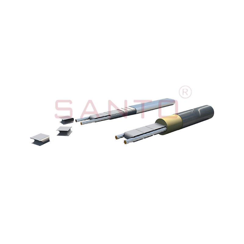
SANTO UFY heating wire is suitable for applications that maintain process temperatures up to 260 ℃ and can be steam blown; The self-regulating and parallel circuit heating wires of the UFY series are ...
See Details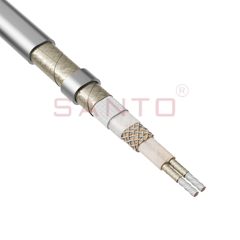
The SANTO UFM series self-regulating heating cables are mainly used for freeze protection of pipes and vessels, but can also be used to maintain processes up to 400°C. These heating cables are availab...
See Details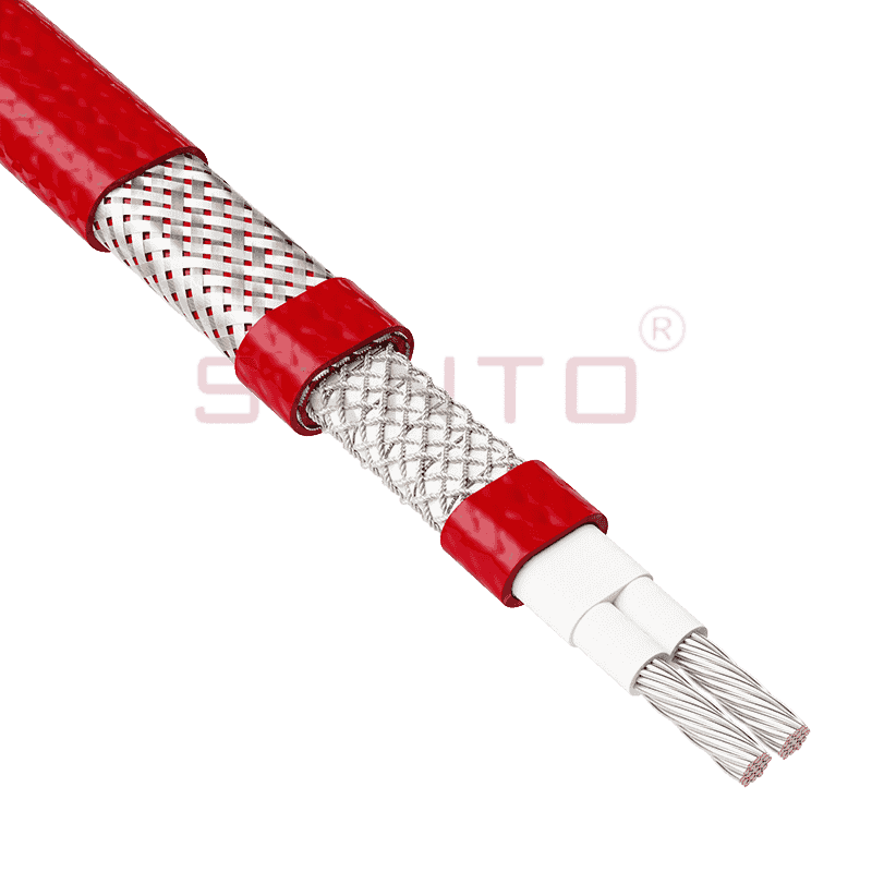
The SANTO ACC range of power-limiting heating cables is mainly used for temperature maintenance of processes and offers the advantage of a high power output at high temperatures which can reduce the n...
See Details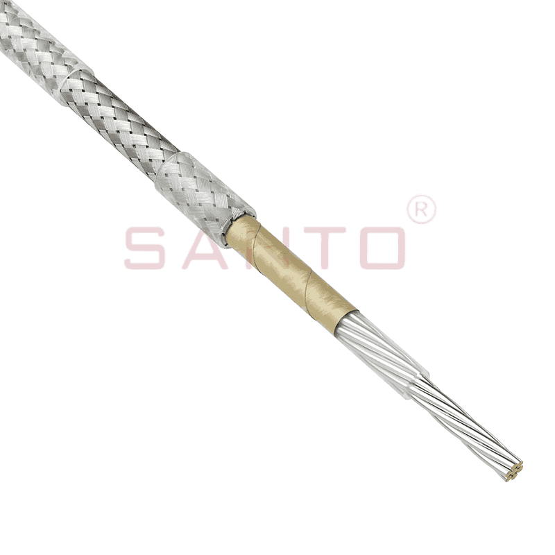
The stranded high temperature conductor is nickel plated to ensure a long life at elevated temperatures in corrosive environments. It is electrically isolated using an innovative sandwich construction...
See Details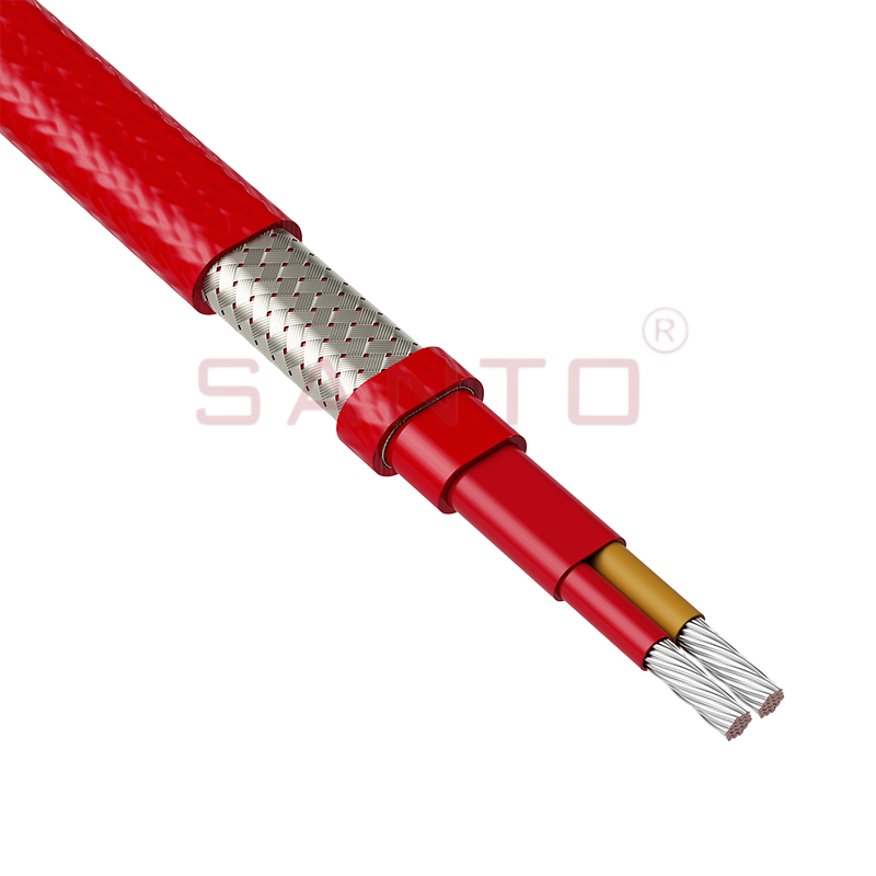
The stranded high temperature conductor is nickel plated to ensure a long life at elevated temperatures in corrosive environments. It is electrically isolated using an innovative sandwich construction...
See Details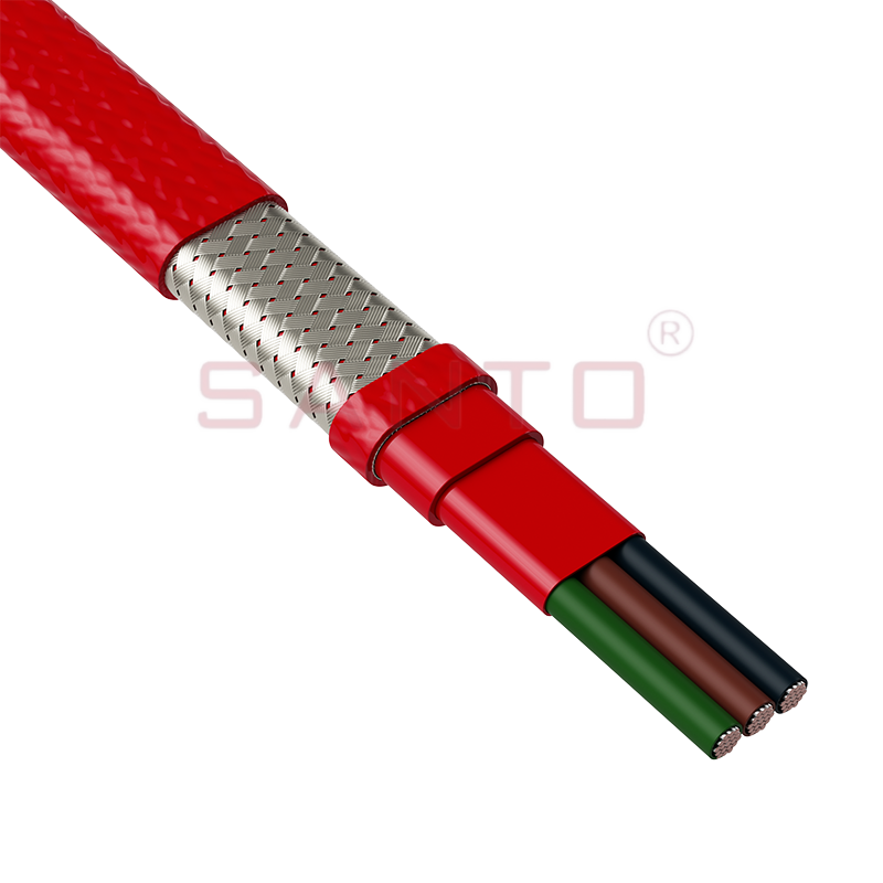
The stranded high temperature conductor is nickel plated to ensure a long life at elevated temperatures in corrosive environments. It is electrically isolated using an innovative sandwich construction...
See Details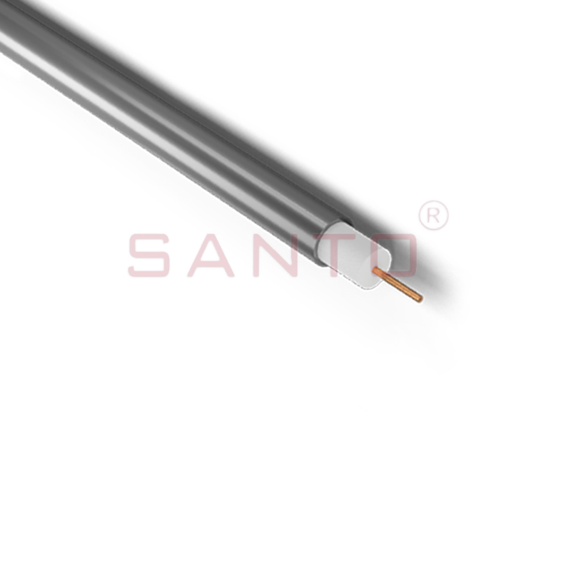
SANTO HAx mineral insulated (MI) Alloy 825 series heating cables are suitable for use in hazardous areas. They have been designed for use in freeze protection and temperature maintenance applications ...
See Details
Santo electric heating strips are widely used in key industries in China.

