 English
 English
 русский
 日本語
 Español
 中文简体

The SANTO UFA range of self-regulating heating cables is mainly used for frost protection of pipes and vessels but can also be used to maintain processes up to 65°C. These heating cables are available...
See Details

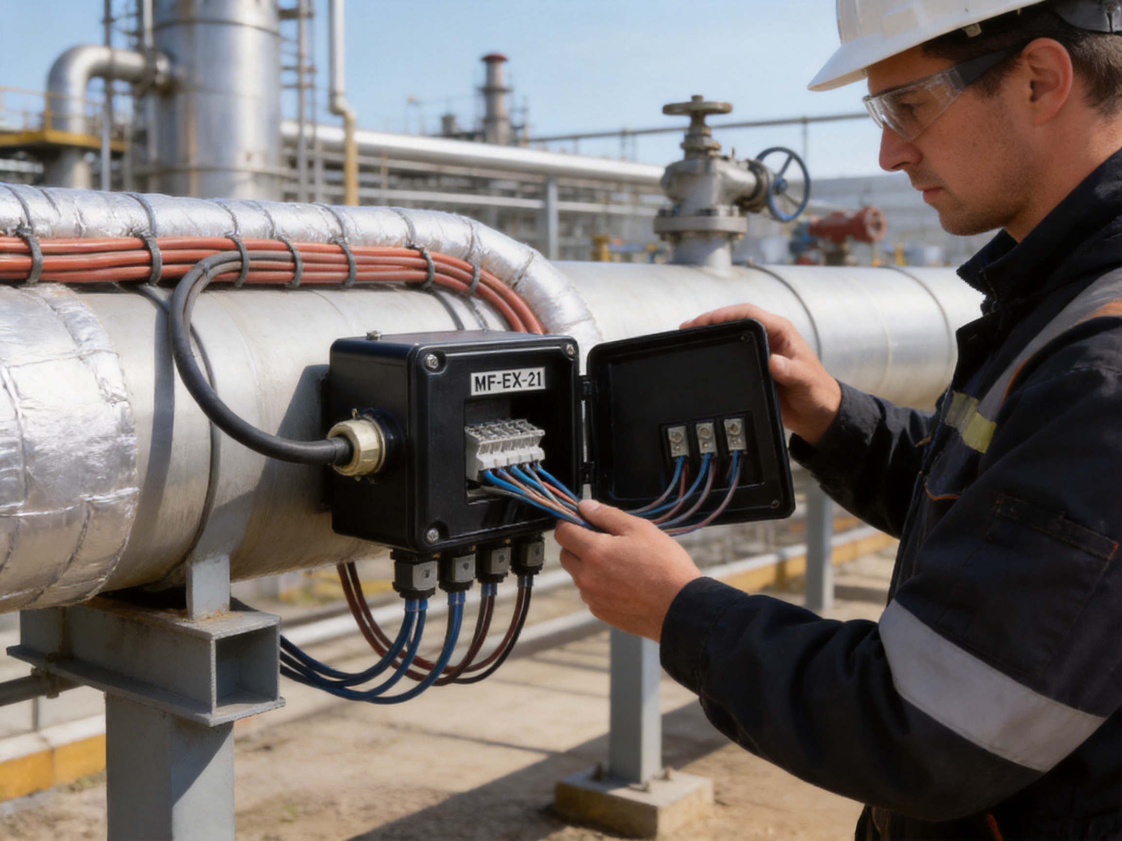
Reliable electrical connections are essential to the safe operation of heat-tracing, freeze-protection, process-heating, and de-icing systems. In demanding industrial environments, a junction box must do far more than contain terminals. It must protect electrical connections from moisture, dust, impact, temperature variation, mechanical stress, and the potentially serious consequences of an unsuitable enclosure or incorrectly selected cable gland.
The MF-EX-21 Multi-Purpose Junction Box is designed for industrial connection, termination, splicing, marshalling, and power distribution duties in hazardous areas. It supports configurations involving power cables, heating cables, and cold cables, including PI and MI heating cable applications when the appropriate connection kits and cable glands are selected. The enclosure combines a robust electrostatic charge-resistant glass-filled engineered polymer body with a sealed silicone gasket, captive stainless-steel lid screws, and DIN-rail-mounted terminals.
Its practical value lies in its flexibility. Depending on the selected configuration, the junction box can serve as a power supply box, end box, splice box, or marshalling box. It can accommodate multiple heating or cold cable connections together with a power cable, while its two terminal options allow users to choose between standard spring-type terminals and a higher-capacity screw-terminal version for larger conductors.
For projects requiring a compact and serviceable hazardous-area enclosure, the MF-EX-21 offers a combination of ingress protection, broad ambient temperature capability, flexible entries, high terminal capacity, and simplified installation. It is particularly suited to industrial heating systems used in petroleum, chemical, gas, construction, energy, process, and infrastructure applications.
Content
Heating cable systems are often installed in locations where normal electrical equipment would be exposed to severe operating conditions. Process pipes may carry corrosive fluids, outdoor equipment may experience rain and snow, and tanks, valves, pumps, and vessels may require continuous freeze protection. In some facilities, flammable gases, vapors, or combustible dusts may also be present.
A junction box in such an environment must maintain electrical continuity while protecting the connection point from external conditions. A weak enclosure, poorly sealed entry, unsuitable terminal, or incorrectly sized gland can compromise the entire heating circuit. The resulting failure may cause loss of heat tracing, freezing, process interruption, maintenance difficulty, or an unsafe electrical condition.
The connection point is also one of the locations where several cable types may meet. A typical installation may include a supply cable, one or more heating cables, cold leads, earth conductors, and cable shields or metallic components. The junction box must provide sufficient physical space, appropriate entry threads, dependable terminals, and a logical wiring arrangement.
The MF-EX-21 has been developed around these practical requirements. Rather than functioning as a basic empty enclosure, it is supplied as a configured junction box with terminals, stopping plugs, temporary rain plugs, and, depending on the model, a terminal jumper. This approach reduces the amount of field assembly required and helps installers begin with a defined connection platform.
The MF-EX-21 is an industrial polyester-style junction box intended for hazardous-area heating cable and power cable connections. Its enclosure is manufactured from electrostatic charge-resistant glass-filled engineered polymer in black. The material provides a nonmetallic construction with good resistance to environmental exposure while helping reduce concerns associated with surface charge accumulation.
The box is sealed with a silicone rubber gasket. The lid is secured by captive stainless-steel screws, so the fixing hardware remains attached to the lid during servicing. This is a useful feature in industrial locations where small loose parts can be misplaced or dropped during maintenance.
The enclosure provides IP66 ingress protection when correctly assembled with suitable glands, stopping plugs, and sealing components. IP66 protection indicates resistance to dust ingress and protection against powerful water jets. The enclosure should still be installed according to the applicable instructions, because the final protection level depends on the condition of the gasket, the correct tightening of entries, and the use of suitable accessories.
Two related configurations are represented in the product information. The first configuration uses spring-type terminals and is identified by the order reference MF-EX-21. The second is a larger-conductor version identified as MF-EX-21/35MM2. The second version is intended for applications requiring larger terminal sizes and uses screw terminals from Weidmuller or an equivalent specified terminal arrangement.
| Feature | Standard Configuration | Large-Conductor Configuration |
|---|---|---|
| Order reference | MF-EX-21 | MF-EX-21/35MM2 |
| Typical entry arrangement | 6 x M20 and 1 x M32 | 6 x M20 and 1 x M40 |
| Terminal style | DIN-rail-mounted spring-type terminals | DIN-rail-mounted screw terminals |
| Maximum conductor size | 10 mm², solid or stranded | 35 mm² stranded and 16 mm² solid |
| Maximum operating voltage | 550 Vac | 690 Vac |
| Maximum operating current | 53 A | 100 A |
| Ingress protection | IP66 | IP66 |
| Ambient temperature range | -55°C to +55°C | -50°C to +55°C |
The selection between the two versions should be based on conductor size, operating current, voltage, heating cable type, available cable glands, and the requirements of the installation design. The larger-terminal model is not simply a replacement for the standard version; it is intended for circuits where the conductor and termination requirements exceed the capacity of the spring-terminal model.
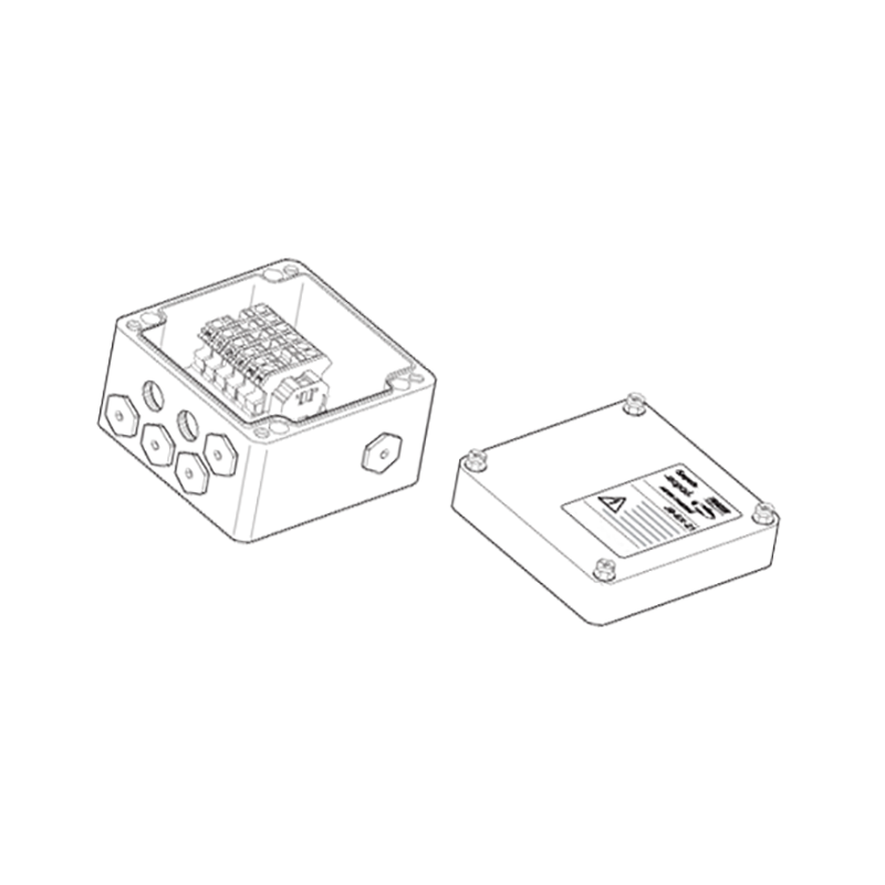
MF-EX-21 Multi-Purpose Junction Box
The junction box can be used in several common arrangements. As a power supply box, it provides a transition between the incoming electrical supply and the heating circuit. As an end box, it provides a termination point for a heating cable or a series circuit. As a splice box, it allows compatible heating and cold cables to be connected. As a marshalling box, it brings several field cables into a structured terminal location for easier routing, testing, and maintenance.
In process heating systems, the box may be installed near a pipe, tank, vessel, valve, pump, or instrument connection. Heating cables can be routed along the equipment to maintain temperature or prevent freezing, while the cold lead returns to a nearby power distribution or control point. A properly selected junction box helps keep the power transition organized and protected.
The product is also appropriate for systems involving PI and MI heating cables when the correct connection kits are used. These cable types may require specific termination methods, insulation entry kits, earth arrangements, and hazardous-area glands. The junction box provides the enclosure and terminal platform, while the cable-specific connection accessories complete the installation.
Potential applications include pipe freeze protection, process temperature maintenance, tank heating, valve and pump protection, loading and unloading systems, chemical process lines, oil and gas facilities, gas treatment systems, outdoor instrumentation, and industrial de-icing. The same basic enclosure can be adapted to different wiring arrangements, which helps reduce the number of separate enclosure designs required across a project.
When used as a power supply box, the MF-EX-21 receives an incoming power cable and distributes the supply to one or more heating circuits. The terminal arrangement can be configured for phase, neutral, and protective earth connections. The standard version provides six terminals and is labeled for phase, neutral, and protective earth functions. The larger version can accommodate more heavily loaded phase and neutral terminals within the permitted total terminal count.
As an end box, the enclosure provides a protected termination point at the end of a heating cable circuit. End termination is especially important where the cable terminates outdoors or in an area exposed to moisture and contamination. The use of an appropriate stopping plug, cable gland, insulation entry kit, and sealing arrangement helps preserve the enclosure’s protective performance.
As a splice box, the product connects heating cables, cold leads, and power conductors through organized DIN-rail terminals. The exact connection method depends on the cable type and the applicable termination kit. The manufacturer specifies that M20 connection kits must be ordered separately according to the heating cable being used. This is important because cable dimensions, insulation systems, earth conductors, and hazardous-area requirements can vary between cable families.
In a marshalling application, the junction box provides a central location for grouping power cable conductors or heating circuit conductors. This can simplify field wiring and make future inspection easier. A marshalling arrangement may also assist with system testing by providing clearly labeled and accessible terminals rather than requiring personnel to work directly at multiple equipment connection points.
The enclosure body and lid are made from glass-filled engineered polymer with resistance to electrostatic charge. This material selection offers several practical advantages over ordinary plastic enclosures. Glass reinforcement improves structural stability, while the engineered polymer construction avoids the corrosion concerns associated with unprotected steel in wet or chemically aggressive environments.
The black enclosure is suitable for industrial installations where equipment may be exposed to sunlight, dirt, oil residue, and general process contamination. A nonmetallic enclosure can also reduce the need for additional surface treatments that would otherwise be required to protect metal from corrosion. At the same time, the box remains a technical electrical enclosure rather than a lightweight general-purpose plastic box.
The silicone rubber sealing gasket creates a continuous sealing interface between the lid and the enclosure body. Silicone rubber is suitable for a broad temperature range and helps maintain sealing performance during outdoor temperature changes. A gasket must be kept clean and undamaged during installation, and the lid screws should be tightened evenly so that the lid compresses the gasket correctly.
The captive stainless-steel screws provide long-term mechanical reliability and make routine inspection more convenient. Stainless steel is selected for its resistance to corrosion in many industrial environments. Because the screws remain connected to the lid, maintenance personnel are less likely to lose them when the box is opened.
The four molded holes in the base allow wall mounting. With an appropriate standard support bracket, the box can also be mounted to a pipe. Pipe mounting is useful where the junction box must remain close to a heated line or where the available wall space is limited. The mounting method should be selected to avoid damaging the enclosure and to ensure that the completed installation remains mechanically stable.
Terminal design is one of the main differences between the MF-EX-21 configurations. The standard model uses spring-type terminals mounted on a DIN rail. Spring terminals provide a fast and repeatable connection method. They maintain contact pressure on the conductor and can reduce the effect of minor conductor movement caused by vibration or thermal cycling.
The standard version has six terminals, with labeling corresponding to phase, neutral, and protective earth functions. The maximum conductor size is 10 mm² for solid and stranded conductors. The maximum operating voltage is 550 Vac and the maximum operating current is 53 A, subject to the complete system design, applicable standards, ambient conditions, and terminal derating requirements.
The terminal arrangement can be adapted through the supplied terminal jumper. The jumper permits various wiring configurations, and the product information indicates that the terminal plate may need to be removed when installing or adjusting the jumper. This feature can assist with different phase, neutral, and circuit distribution arrangements, but it should only be changed by qualified personnel following the wiring diagram for the specific installation.
The MF-EX-21/35MM2 version uses screw terminals intended for larger conductors. Its listed capacity reaches 35 mm² for stranded conductors and 16 mm² for solid conductors. The model is rated for up to 690 Vac and 100 A under the stated conditions. The terminal arrangement includes phase and neutral terminals, heating-cable earth terminals, and a power-cable earth terminal.
The large-conductor model can accommodate up to six fully loaded phase or neutral terminals, with a maximum of ten terminals installed in total. This limitation is important. Adding terminals beyond the specified quantity can affect spacing, heat dissipation, enclosure fit, and the electrical certification or design basis of the product. Installers should not treat the enclosure as an unrestricted empty box.
| Terminal Consideration | Installation Significance |
|---|---|
| Conductor size | Select the terminal version that matches the conductor cross-section and conductor type. |
| Operating current | Confirm that the terminal, cable, gland, and protection device are suitable for the design current. |
| Protective earth | Maintain the required earth continuity for heating cables and incoming power cables. |
| Terminal quantity | Do not exceed the stated maximum number of installed terminals. |
| Terminal jumper | Use only for the approved wiring arrangement and follow the relevant circuit diagram. |
| Spacing and heat | Allow sufficient space for conductor bending, inspection, and heat dissipation. |
These terminal choices give the product an advantage over a one-size-fits-all junction box. Smaller heating circuits can use the compact spring-terminal arrangement, while higher-capacity applications can use the screw-terminal version. The project designer does not have to compromise by using oversized equipment for every circuit or by forcing large conductors into terminals that were not designed for them.
The standard configuration provides six M20 entries and one M32 entry. The larger-conductor configuration provides six M20 entries and one M40 entry. These entries allow the enclosure to be arranged for several heating cable and cold cable connections, together with an incoming or outgoing power cable.
M20 entries are commonly used for heating cable connection kits and cold cable glands. The larger M32 or M40 entry is intended for a power cable or another cable requiring a larger gland. The actual gland must be selected according to cable diameter, thread form, hazardous-area requirements, armor or shield construction, sealing method, and the relevant installation standards.
Accessories listed for the product include hazardous-area-approved glands, stopping plugs, temporary rain plugs, reducers, insulation entry kits, support brackets, loose terminals, end plates, and terminal jumpers. These components are not interchangeable in every application. For example, a gland approved for a certain cable diameter cannot automatically be used with a cable outside its specified range.
For the standard version, the listed power-cable gland is a GL-45-M32 type for cables with a diameter range of approximately 12 to 21 mm. The heating cable gland is listed as a GL-44-M20-KIT for cables with a diameter range of approximately 5.5 to 13 mm. The product information also identifies separate accessories for phase, earth, end plate, and terminal jumper functions.
For the larger-conductor version, listed power-cable options include M40 and M32 glands for different cable diameters, as well as an M20 gland for smaller cables. A hazardous-area M40-to-M32 reducer is available where the selected cable gland and enclosure entry require that transition. For PI cold leads, the GL-44-M20-KIT and IEK-20-PI insulation entry kit are listed. MI cable arrangements may require factory-terminated units or specific manufacturer-approved termination methods.
The supplied stopping plugs close unused entries during installation. Temporary rain plugs are intended to provide temporary protection before the final cable glands or permanent plugs are installed. Temporary components should not be assumed to replace final approved sealing components in a completed hazardous-area installation.
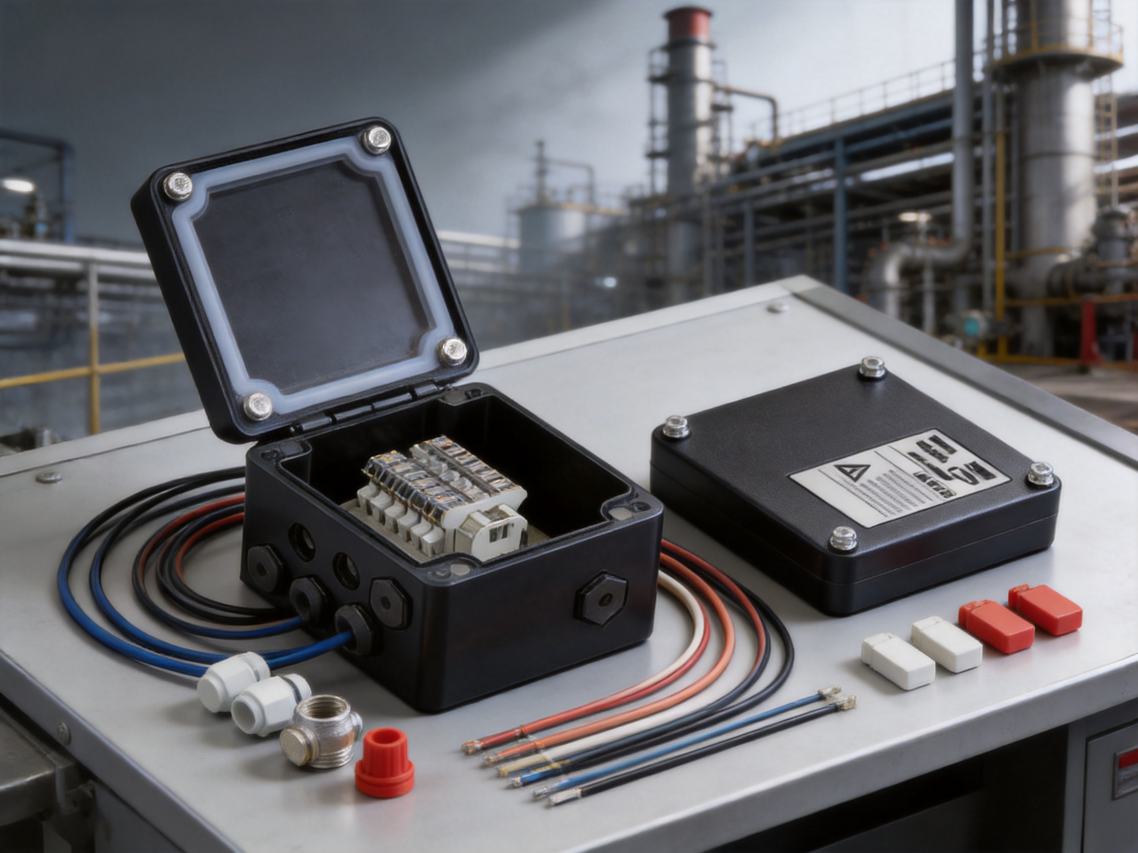
The MF-EX-21 is specified with IP66 ingress protection. This level is important for outdoor heating systems because a junction box may be exposed to wind-driven rain, water spray during cleaning, dust, and process contamination. Dust-tight construction also helps protect terminals from conductive or abrasive particles.
Achieving IP66 in practice depends on more than the enclosure body. The lid gasket must be correctly positioned, the lid must be properly secured, all cable entries must use suitable glands, and unused openings must be closed with compatible stopping plugs. Threads and sealing surfaces should be kept free from dirt, damaged components should be replaced, and cable glands should be tightened according to their instructions.
The standard model has an ambient temperature range of -55°C to +55°C. The large-conductor version is listed for -50°C to +55°C. These ranges make the enclosure suitable for many cold outdoor and industrial environments, but the heating cable itself, cable gland, terminal, and other accessories must also be checked for compatible temperature ratings.
Temperature rating is especially important in trace-heating applications. The surrounding air temperature may be low while the equipment surface is warm, and local temperature can vary according to insulation, process temperature, heating output, and control performance. The complete assembly must therefore be evaluated rather than selecting the enclosure based only on ambient air temperature.
The polymer enclosure also helps avoid the surface corrosion that can occur on ordinary painted steel boxes. This can be valuable in chemical plants, coastal facilities, wastewater environments, and outdoor process installations. Nevertheless, the exact chemical compatibility of the enclosure and gasket should be confirmed when the box will be exposed to aggressive chemicals, solvents, or unusual process contaminants.
Many general-purpose junction boxes provide only an empty shell or a basic terminal strip. The MF-EX-21 is designed around heating cable connection requirements. It offers multiple M20 entries for heating and cold cable arrangements, a larger entry for power cable connection, and accessory compatibility with PI and MI heating cable systems.
This purpose-built approach can reduce design uncertainty. Instead of adapting a general enclosure through extensive field modifications, the installer can select a product configuration and order the appropriate cable-specific kits. This supports more consistent installation across repeated project locations.
The availability of a spring-terminal version and a 35 mm² screw-terminal version allows the product family to address both ordinary and high-capacity connections. Competitors that offer only small spring terminals may not be suitable for higher-current heating circuits, while oversized metal boxes may be unnecessarily expensive or physically difficult to install on smaller systems.
The glass-filled engineered polymer body resists many common environmental problems associated with unprotected metal. It does not require the same type of paint maintenance as a steel enclosure, and it is less vulnerable to surface rust. This can reduce lifecycle maintenance in wet or corrosive service locations.
DIN-rail-mounted terminals provide an organized wiring platform. Captive lid screws reduce the risk of lost hardware, while the molded mounting holes support straightforward wall installation. The ability to add a standard pipe support bracket extends the mounting options without requiring a special enclosure design.
The product is suitable for power supply, end, splice, and marshalling functions. Its flexible entry arrangement supports several system layouts, and the terminal jumper allows different approved wiring configurations. This versatility can help contractors standardize on one junction box family across multiple areas of a facility.
IP66 sealing, an electrostatic charge-resistant enclosure, stainless-steel captive screws, and a silicone gasket provide a stronger environmental package than an ordinary indoor junction box. When combined with approved glands and correct installation procedures, these features help protect the connection point in challenging industrial locations.
The product is supplied by Santo Thermal Control Technology Co., Ltd., a manufacturer focused on electric heating and thermal control products. Its product scope includes self-limiting heating cables, constant-power heating cables, silicone rubber heating systems, glass-fiber heating products, MI cables, snow-melting cables, heat-tracing accessories, and related electrical heating equipment.
This specialization is significant because junction boxes for heating systems must be designed with an understanding of cable construction, termination methods, power distribution, thermal behavior, and field installation. A manufacturer that produces heating cable systems can develop connection accessories with closer attention to the practical needs of heating cable contractors and system integrators.
The company describes an integrated approach covering research, design, production, manufacturing, and sales. Its stated development history includes long-term work in electric heating technology, the establishment of the SANTO brand, expansion of manufacturing capacity, product simulation and testing facilities, and the development of international market channels.
The manufacturer reports ISO9001 quality system certification and national CCC certification for its products. It also reports explosion-proof and EAC Eurasian Union certification activities connected with its product development and market expansion. Certification claims must always be checked against the exact product model, certificate number, intended hazardous-area classification, gas or dust group, temperature class, and installation conditions.
Manufacturing strength is not measured only by production volume. It also includes material control, terminal assembly, dimensional consistency, sealing inspection, electrical testing, traceability, documentation, and the ability to adapt products for different heating cable types. These factors are particularly important in hazardous-area equipment, where an apparently small change in a gland, terminal, or enclosure component may affect the compliance of the complete assembly.
The company’s stated business scale includes more than 35 years of industry experience, annual output exceeding 10,000 units or products, more than 2,000 distributors, and business coverage in more than 85 areas. Such a distribution and application network can support spare-parts availability, local technical communication, and project sourcing, although customers should confirm regional stock and service arrangements before placing an order.
Product development experience in self-limiting heating belts, constant-power heating products, silicone rubber heaters, MI cables, and snow-melting cables also supports broader system integration. Customers can source not only the junction box but potentially the associated heating technology, accessories, and engineering guidance from a supplier familiar with the complete application.
A dependable junction box begins with material consistency. The engineered polymer must be properly compounded and molded so that the enclosure maintains its mechanical shape, mounting dimensions, lid fit, and resistance to environmental conditions. Glass-fiber distribution, molding temperature, cooling, and dimensional control all influence the quality of the finished body.
Gasket quality is equally important. The silicone gasket must be formed to the correct profile and installed without twisting, cuts, contamination, or compression damage. The lid and enclosure mating surfaces must be inspected so that the gasket can perform as intended.
Terminal assembly requires controlled workmanship. DIN rails should be securely fixed, terminals should be correctly positioned, labels should be legible, and terminal jumpers should be installed only where the selected configuration requires them. Screw terminals must be tightened according to the terminal manufacturer’s specified torque. Spring terminals require correct stripping lengths and conductor insertion procedures.
Accessory matching should be controlled through product references. The listed glands and kits are associated with specific entry sizes, cable diameter ranges, and heating cable families. A manufacturing and supply system that maintains clear part numbers helps reduce the risk of mixing similar-looking accessories with different technical ratings.
Finished-product inspection should include enclosure appearance, lid fit, gasket placement, entry thread condition, terminal installation, labeling, and electrical continuity. For products intended for hazardous locations, documentation and certification control are as important as physical inspection. The delivered product should be traceable to the correct technical specification.
These manufacturing principles create a practical advantage over low-cost generic boxes that may have inconsistent dimensions, poorly fitting lids, weak mounting points, or terminals that are not matched to the enclosure. In hazardous-area heating systems, a lower purchase price can be outweighed by installation delays, rework, premature corrosion, or difficulty obtaining compatible replacement parts.
Before installation, the designer should identify the heating cable type, the number of heating circuits, conductor cross-sections, supply voltage, design current, environmental temperature, hazardous-area classification, and cable entry requirements. These details determine whether the standard MF-EX-21 or the MF-EX-21/35MM2 version is appropriate.
The installer should prepare a wiring diagram showing incoming supply conductors, outgoing heating conductors, cold leads, protective earth conductors, terminal jumpers, and any required shields or drain wires. The drawing should identify the terminal numbers and cable entry used for each circuit.
The junction box should be mounted where it remains accessible for inspection and maintenance. It should not be positioned where water can collect around the lid or entries, where mechanical impact is likely, or where the box will be subjected to temperatures beyond the stated range. When pipe mounting is selected, the support bracket should be suitable for the pipe diameter and the total weight of the installed box and cables.
Cables should be routed so that they do not place excessive pulling force or bending stress on the glands. The minimum bending radius specified by the cable manufacturer should be respected. Cable entries should be arranged to provide orderly conductor routing and sufficient separation for termination.
Unused entries must be closed with appropriate stopping plugs. Temporary rain plugs are useful during staged construction but should be replaced by final components before commissioning. All glands and plugs should be compatible with the enclosure entry thread and the hazardous-area requirements of the installation.
After wiring, the installer should verify terminal torque, conductor insertion, earth continuity, insulation condition, cable identification, lid gasket placement, and enclosure closure. Testing should follow the project commissioning plan and applicable electrical standards. The box should not be energized until the complete heating circuit has passed the required inspections and tests.
Routine inspection should check the enclosure for impact damage, ultraviolet deterioration, chemical attack, loose mounting hardware, damaged glands, missing plugs, and gasket deterioration. The lid should be opened only when permitted by the operating procedure and only after the circuit has been isolated where required.
Terminals should be inspected for signs of overheating, discoloration, corrosion, loose conductors, or damaged insulation. A thermal or electrical abnormality may indicate overloading, an incorrect terminal, a loose connection, unsuitable conductor size, or a problem elsewhere in the heating circuit.
The enclosure should be cleaned using methods compatible with the polymer and gasket materials. Abrasive tools or aggressive solvents should not be used unless specifically approved. Dirt should not be allowed to build up around the gasket or entry seals.
Replacement parts should match the original product specification. Substituting an unapproved gland, gasket, terminal, or stopping plug can compromise protection and may invalidate the applicable certification basis. For this reason, maintaining a record of the product order reference, accessories, cable types, and installation date is recommended.
Project engineers can use the following sequence when evaluating the product:
First, determine whether the enclosure’s hazardous-area approval and environmental ratings match the installation. Regional approval information in the product material identifies Russia, Kazakhstan, and Belarus, while customers in other regions are advised to contact the local representative for applicable certification information.
Second, confirm the cable types. PI, MI, power, and cold cables may require different glands, termination kits, insulation entry kits, or factory-terminated arrangements.
Third, calculate the number of cables and conductors. The entry arrangement must be sufficient without using unauthorized drilling or modification. The number of terminals must remain within the stated maximum.
Fourth, select the terminal capacity. The standard version is suitable for conductors up to 10 mm² and current up to 53 A under the stated rating. The large-conductor version supports conductors up to 35 mm² stranded or 16 mm² solid and is rated up to 100 A under the stated conditions.
Fifth, check the ambient temperature and process temperature. The box, gasket, terminal, cable, gland, and connection kit must all be suitable for the expected temperature profile.
Sixth, specify the mounting method. Wall mounting uses the molded base holes, while pipe mounting requires a suitable support bracket such as the listed SB-100 or SB-101 accessories.
Finally, define the documentation package. This may include product data, wiring diagrams, gland certificates, hazardous-area certificates, installation instructions, inspection records, and commissioning test results.
| Selection Question | Relevant Product Information |
|---|---|
| What type of enclosure is required? | Industrial hazardous-area junction box for heating and power cable connections. |
| What protection level is needed? | IP66, provided the box is correctly assembled with suitable accessories. |
| Which terminal version is suitable? | Spring terminals up to 10 mm², or screw terminals up to 35 mm² stranded and 16 mm² solid. |
| How many entries are available? | Standard: 6 x M20 and 1 x M32. Large-conductor version: 6 x M20 and 1 x M40. |
| Can it be pipe mounted? | Yes, with a suitable standard support bracket. |
| Are heating cable kits included? | No. M20 connection kits and certain glands are ordered separately according to cable type. |
| What is the standard ambient range? | -55°C to +55°C for the standard version; -50°C to +55°C for the large-conductor version. |
It is used to make protected electrical connections between power cables, heating cables, and cold cables in industrial and hazardous-area installations. It can function as a power supply box, end box, splice box, or marshalling box.
Yes, the product information identifies applications with PI and MI heating cables. The correct connection kit, gland, insulation entry kit, and termination method must be selected for the specific cable type. Some MI cable arrangements may require factory-terminated units.
No. The M20 connection kits are ordered separately according to the type of heating cable being used. This allows the installer to select a kit that matches the cable construction and diameter.
The standard MF-EX-21 uses DIN-rail-mounted spring-type terminals for conductors up to 10 mm² and is listed for up to 550 Vac and 53 A. The MF-EX-21/35MM2 uses screw terminals for larger conductors up to 35 mm² stranded or 16 mm² solid and is listed for up to 690 Vac and 100 A.
The standard configuration includes six terminals. The large-conductor configuration can accommodate up to six fully loaded phase or neutral terminals, with a maximum of ten terminals in total. The stated limit should not be exceeded.
The enclosure is specified as IP66. This protection level depends on correct assembly, proper gasket installation, suitable cable glands, correctly fitted stopping plugs, and maintenance of the enclosure sealing surfaces.
Yes, it is designed for industrial use and has a listed ambient temperature range suitable for many outdoor installations. The complete assembly must be checked for temperature, ultraviolet exposure, chemical compatibility, hazardous-area classification, and accessory suitability.
Yes. The box can be wall mounted through the four molded holes in the base. Pipe mounting is possible with an appropriate support bracket, such as the listed SB-100 or SB-101 type.
The selection depends on the junction box version and cable diameter. The standard configuration lists an M32 hazardous-area-approved gland for cables approximately 12 to 21 mm in diameter. The large-conductor version provides M40, M32, and M20 gland options for different cable sizes.
They are intended for temporary protection during installation. Final unused entries should be closed with appropriate permanent stopping plugs approved for the installation conditions.
The box and lid are made from black, electrostatic charge-resistant glass-filled engineered polymer. The sealing gasket is silicone rubber, and the captive lid screws are stainless steel.
The project team should confirm hazardous-area approval, cable type, cable diameter, conductor size, current, voltage, ambient and process temperatures, number of entries, mounting method, terminal arrangement, and the required glands and connection kits.
A supplier focused on electric heating and thermal-control products can provide better system compatibility because the enclosure, heating cable, termination kit, and accessory requirements are considered together. This can reduce the risk of mismatched components and simplify technical coordination.
The MF-EX-21 Multi-Purpose Junction Box is a flexible industrial enclosure for organizing and protecting heating cable and power cable connections in demanding environments. Its IP66 construction, electrostatic charge-resistant engineered polymer body, silicone gasket, captive stainless-steel screws, and DIN-rail terminal system provide a practical foundation for reliable field installation.
Its strongest advantage is the combination of application flexibility and terminal choice. The standard spring-terminal model supports compact heating cable circuits, while the MF-EX-21/35MM2 version extends the product family to larger conductors, higher operating current, and higher voltage applications. Multiple M20 entries and a larger M32 or M40 entry allow the enclosure to be configured for power, heating, cold cable, splice, and marshalling duties.
The product is most effective when specified as part of a complete engineered system. Correct glands, connection kits, stopping plugs, insulation entry kits, terminal jumpers, and support brackets are essential to achieving the intended performance. Installation should be carried out by qualified personnel in accordance with the applicable hazardous-area, electrical, and manufacturer requirements.
Supported by a manufacturer specializing in electric heating and thermal-control technology, the junction box fits naturally into heat-tracing, freeze-protection, process-heating, snow-melting, and industrial de-icing projects. Its material selection, terminal options, accessory range, and manufacturing background make it a strong candidate for projects that require dependable heating cable connections rather than a generic empty enclosure.
1. MF-EX-21 Multi-Purpose Junction Box Product Specification, supplied technical product information.
2. MF-EX-21/35MM2 Junction Box Technical Data, supplied terminal and accessory specifications.
3. Industrial Electrical Enclosure Protection Classification Reference, IP66 environmental protection principles.
4. Hazardous-Area Cable Gland Selection and Installation Practice, general engineering guidance.
5. DIN-Rail Terminal Installation and Wiring Practice, general industrial electrical reference.
6. Quality Management Systems for Manufacturing Organizations, ISO 9001 principles.
7. Electric Heating and Heat-Tracing System Design Practice, general application reference.
8. Santo Thermal Control Technology Co., Ltd. Company and Product Information, supplied corporate materials.
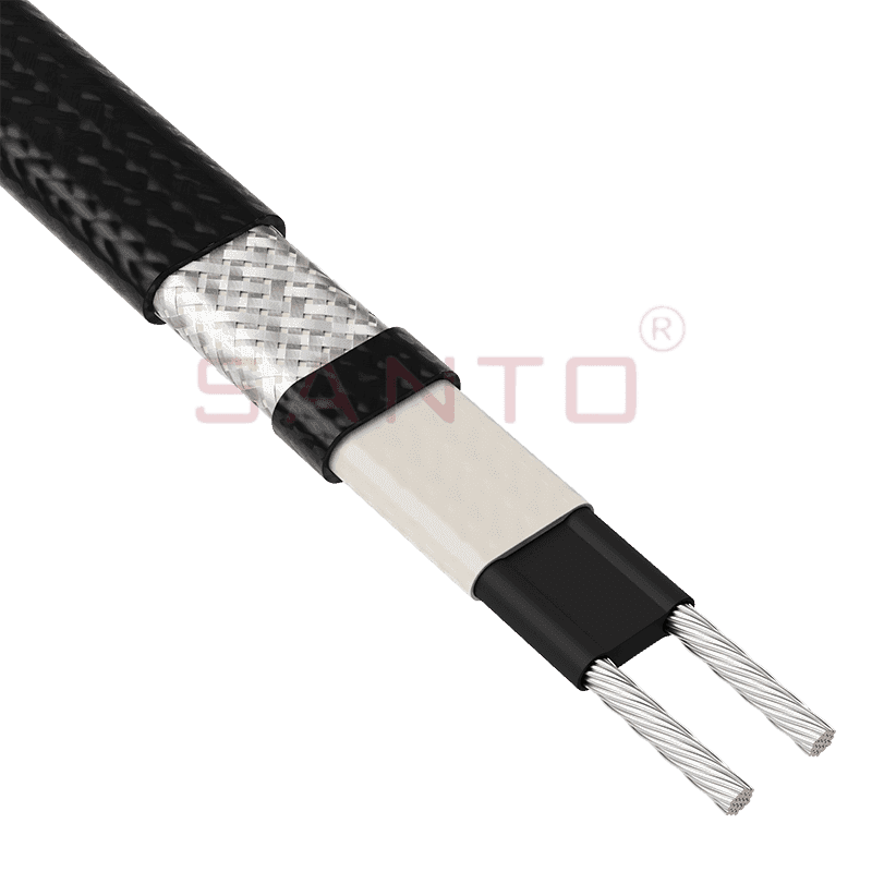
The SANTO UFA range of self-regulating heating cables is mainly used for frost protection of pipes and vessels but can also be used to maintain processes up to 65°C. These heating cables are available...
See Details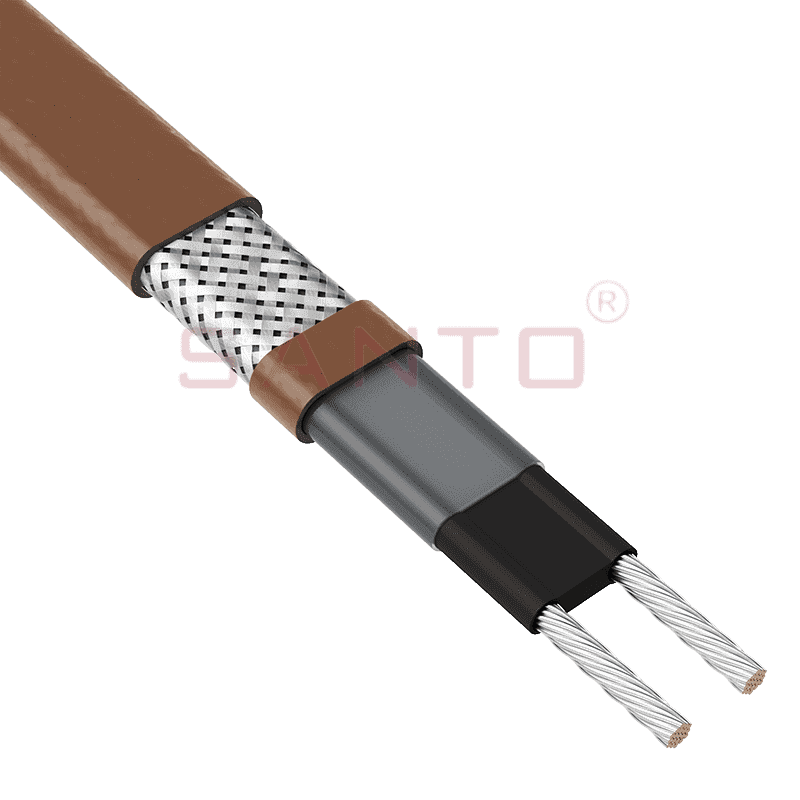
The SANTO UFB range of self-regulating heating cables is mainly used for frost protection of pipes and vessels requiring a higher power output than the UFA heating cables can supply. They can also be ...
See Details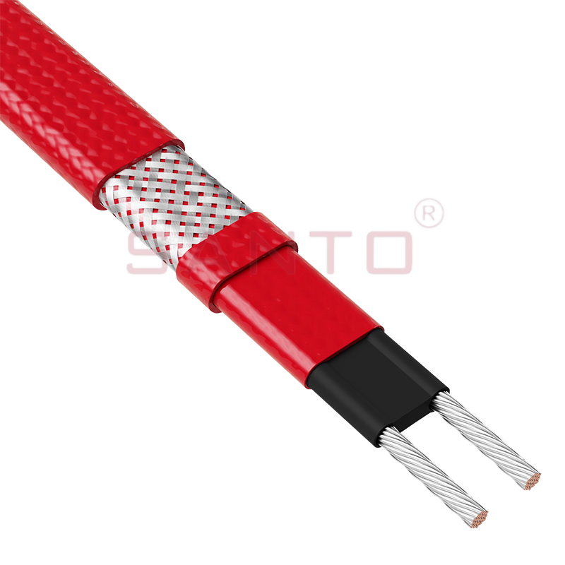
The SANTO UFC range of self-regulating heating cables is used for frost protection of pipes and vessels that require steam cleaning. They can also be used to maintain processes up to 121°C. These heat...
See Details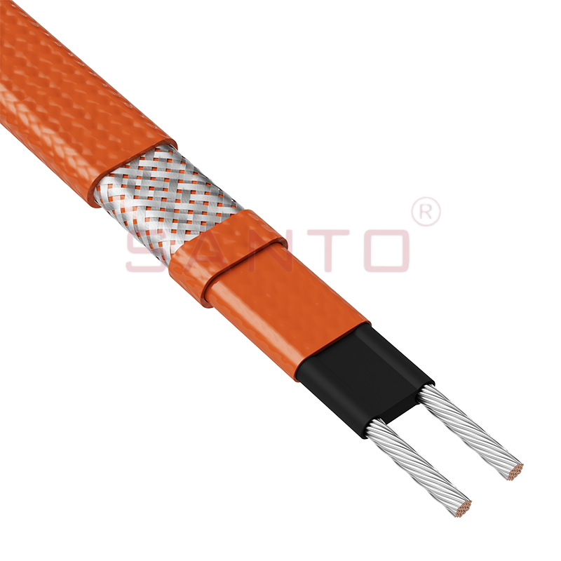
The SANTO UFO range of self-regulating heating cables is mainly used for frost protection of pipes and vessels that require steam cleaning . They can also be used to maintain processes up to 150°C. Th...
See Details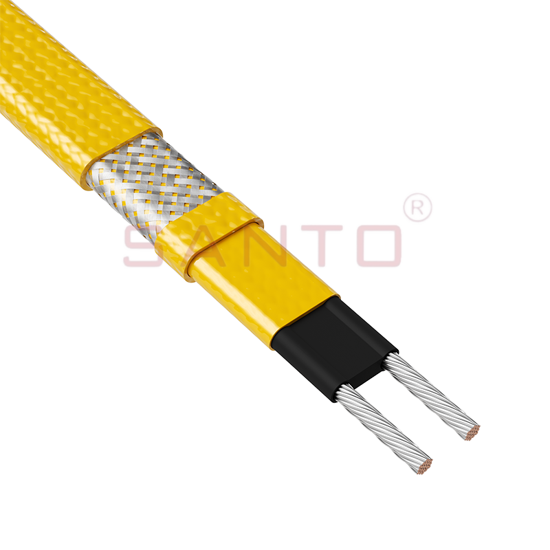
The SANTO UFD series of self-regulating heating cables are mainly used for freeze protection of pipes and vessels, but can also be used to maintain processes up to 200°C. These heating cables are avai...
See Details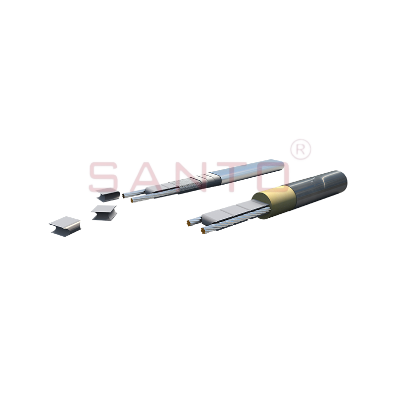
SANTO UFY heating wire is suitable for applications that maintain process temperatures up to 260 ℃ and can be steam blown; The self-regulating and parallel circuit heating wires of the UFY series are ...
See Details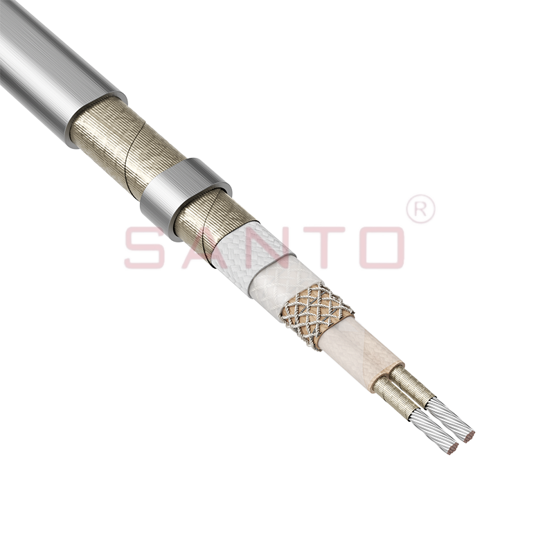
The SANTO UFM series self-regulating heating cables are mainly used for freeze protection of pipes and vessels, but can also be used to maintain processes up to 400°C. These heating cables are availab...
See Details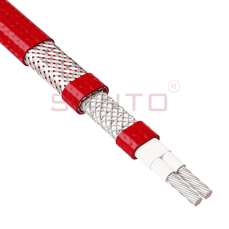
The SANTO ACC range of power-limiting heating cables is mainly used for temperature maintenance of processes and offers the advantage of a high power output at high temperatures which can reduce the n...
See Details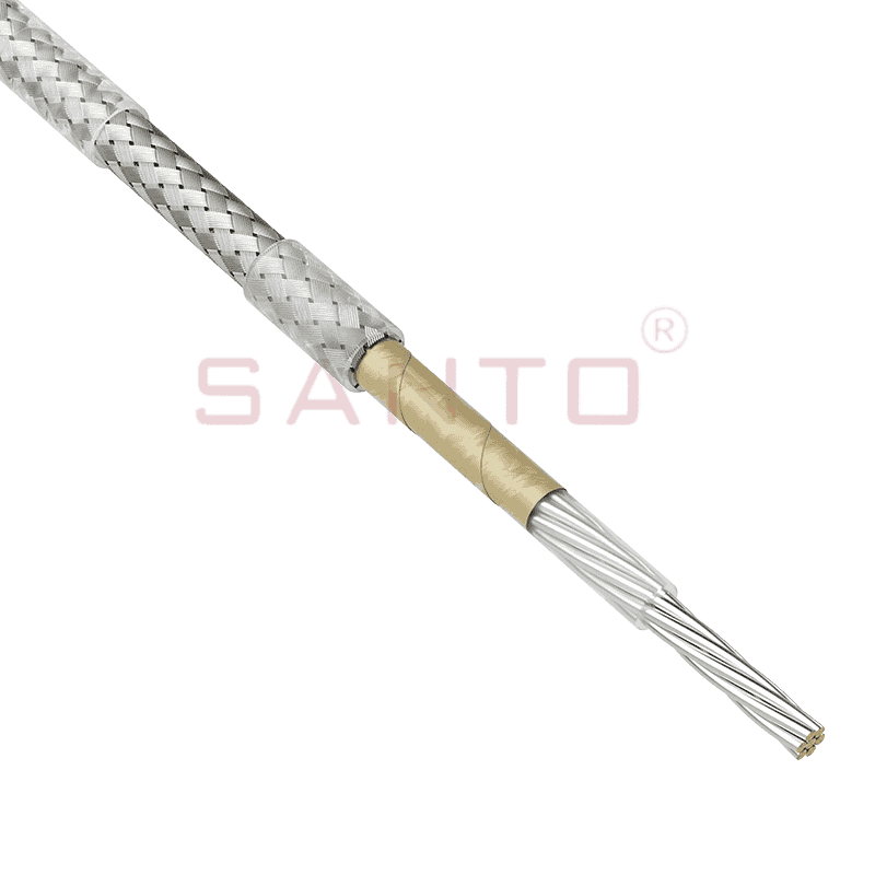
The stranded high temperature conductor is nickel plated to ensure a long life at elevated temperatures in corrosive environments. It is electrically isolated using an innovative sandwich construction...
See Details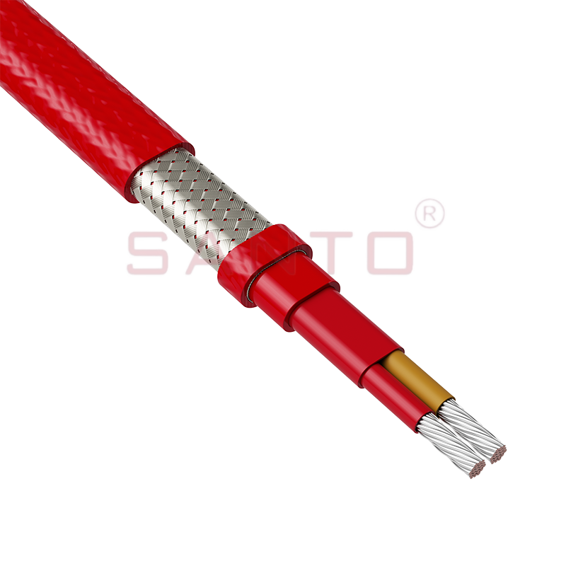
The stranded high temperature conductor is nickel plated to ensure a long life at elevated temperatures in corrosive environments. It is electrically isolated using an innovative sandwich construction...
See Details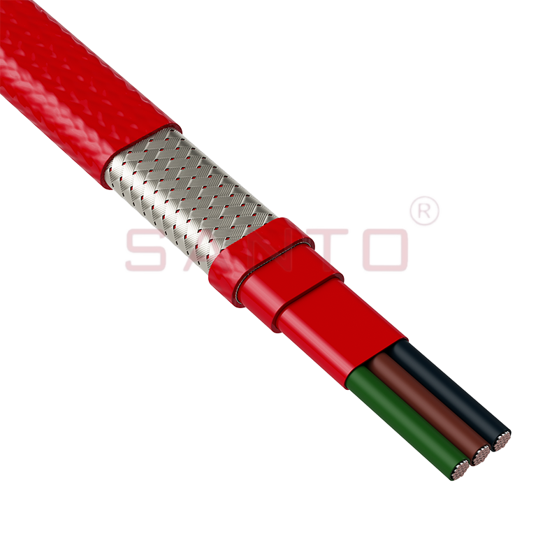
The stranded high temperature conductor is nickel plated to ensure a long life at elevated temperatures in corrosive environments. It is electrically isolated using an innovative sandwich construction...
See Details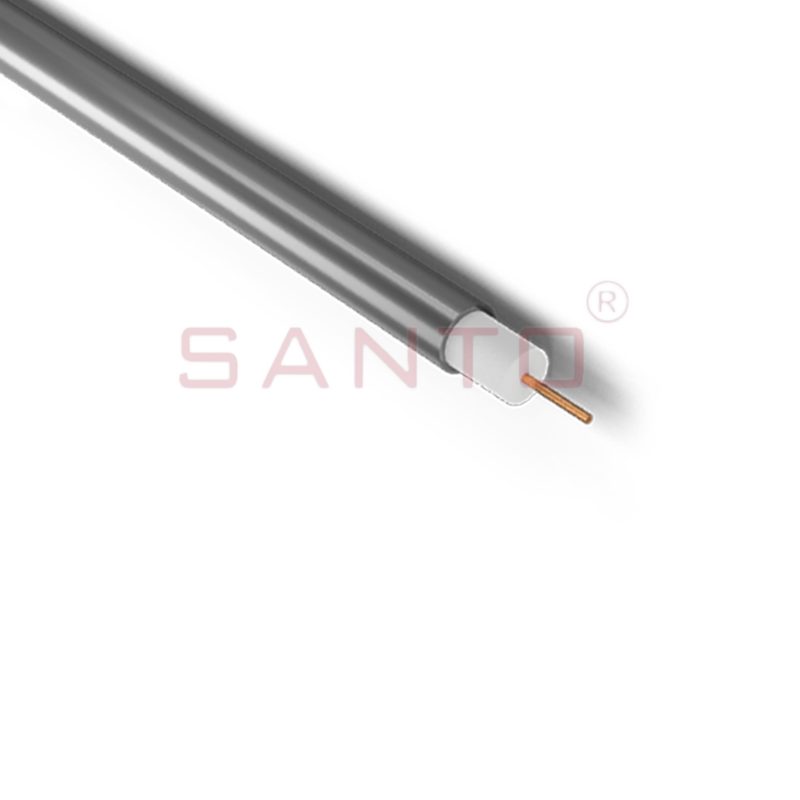
SANTO HAx mineral insulated (MI) Alloy 825 series heating cables are suitable for use in hazardous areas. They have been designed for use in freeze protection and temperature maintenance applications ...
See Details
Santo electric heating strips are widely used in key industries in China.

