 English
  English
 русский
 日本語
日本語 Español
 中文简体
中文简体
The SANTO UFA range of self-regulating heating cables is mainly used for frost protection of pipes and vessels but can also be used to maintain processes up to 65°C. These heating cables are available...
See Details
Long-distance pipelines require a heating solution that can deliver dependable thermal performance over many kilometers while remaining electrically safe, mechanically robust, and practical to install. Conventional electric heat-tracing cables are often effective on short and medium-length pipelines, but their limitations become more significant as the heated distance increases. Voltage drop, parallel power distribution, multiple connection points, complicated control arrangements, and maintenance requirements can make a conventional system difficult and expensive to operate.
The STS HV Skin-Effect Tracing Wire is designed specifically for demanding pipeline heating applications where long-distance performance, single-ended power supply, high output, and operational reliability are essential. The system uses a thermally rated insulated conductor installed inside a ferromagnetic heat tube. When alternating current is applied between the insulated conductor and the heat tube, the system creates heat through the skin effect, proximity effect, electrical resistance, eddy currents, and magnetic hysteresis.
Unlike a conventional cable that transfers most of its heat from a relatively small resistance wire, the STS arrangement uses the ferromagnetic tube as the primary heating element. Current becomes concentrated on the inner surface of the tube, allowing the tube to heat efficiently while its outside surface remains close to electrical ground potential. Because the heat tube is installed directly against the process pipe and enclosed within the thermal insulation, the generated heat can be transferred efficiently to the pipeline.
This technology is suitable for temperature maintenance, freeze prevention, antifreeze protection, process heating, and long-distance pipeline heating. It can be used for pipelines installed above ground, underground, or underwater, including applications located in areas with explosive hazards when the complete system is designed and certified according to the applicable requirements.
Content
The STS system consists of three principal elements: a ferromagnetic heat tube, an insulated internal conductor, and a power and termination arrangement. The internal conductor runs through the heat tube over the required heating length. At the far end of the heating circuit, the conductor is electrically connected to the tube. At the power end, an alternating-current voltage source is connected between the conductor and the heat tube.
This creates a closed electrical path. Current travels through the internal conductor toward the remote end, transfers to the heat tube at the end termination, and returns through the inside surface of the heat tube toward the power connection. The arrangement allows the entire length of the heating tube to function as an extended heating element.
The heat tube is normally manufactured from carbon steel or another suitable ferromagnetic material. Typical heating tube dimensions may include an outside diameter from approximately 20 to 60 millimeters, a wall thickness of not less than 3 millimeters, and an internal passage suitable for the insulated conductor. The exact tube dimensions, conductor size, supply voltage, heating length, and output power are selected according to the pipeline design and thermal calculation.
In a completed installation, the heat tube is attached to the process pipe and covered by the thermal insulation system. The heat path is therefore short and direct. This reduces thermal resistance between the heating element and the process medium and helps limit heat loss to the surrounding environment.
The system is especially valuable where a pipeline must be heated continuously over a substantial distance. The stated maximum heating-line length can reach 30 kilometers, depending on the electrical design, supply voltage, pipe conditions, insulation, ambient temperature, required process temperature, and permissible operating parameters.
Skin effect is the tendency of alternating current to concentrate near the surface of a conductor rather than distribute evenly through its entire cross-section. The depth of current penetration depends on the material, frequency, magnetic permeability, electrical resistivity, and operating temperature.
In a nonmagnetic conductor at commercial power frequency, the skin effect may be relatively limited. In a ferromagnetic carbon-steel tube, however, the higher magnetic permeability causes the alternating current to concentrate strongly near the inner wall. The current returning through the tube is therefore concentrated in a relatively thin inner layer rather than occupying the complete wall thickness.
Proximity effect also contributes to current concentration. When two conductors carrying alternating current are positioned close to one another, the electromagnetic fields produced by the conductors influence the current distribution. In the STS design, the internal conductor and the surrounding heat tube are arranged concentrically. Their electromagnetic relationship encourages current to flow in the desired regions and supports efficient heating of the tube.
Heat is produced through several related mechanisms:
1. Electrical resistance in the heat tube produces heat as current flows through the concentrated inner layer.
2. Electrical resistance in the insulated internal conductor also contributes to the total heat output.
3. Eddy currents are induced in the ferromagnetic tube by the alternating magnetic field.
4. Magnetic hysteresis losses occur as the magnetic domains in the ferromagnetic material repeatedly change orientation under alternating excitation.
The combined effect is a practical and efficient heating system in which a large proportion of the output power is generated in the carbon-steel heat tube. The product information indicates that approximately 80 percent of the main output power may be generated in the carbon-steel tube under suitable operating conditions.
Because the current is concentrated on the inner surface, the outer wall of the heat tube has very low measurable potential in normal operation. This electrical characteristic helps improve system safety and means that the outer surface does not necessarily require the same type of electrical insulation used by exposed conventional resistance heating cables. Nevertheless, grounding, bonding, insulation coordination, protection, and installation procedures must always be designed and verified by qualified electrical professionals.
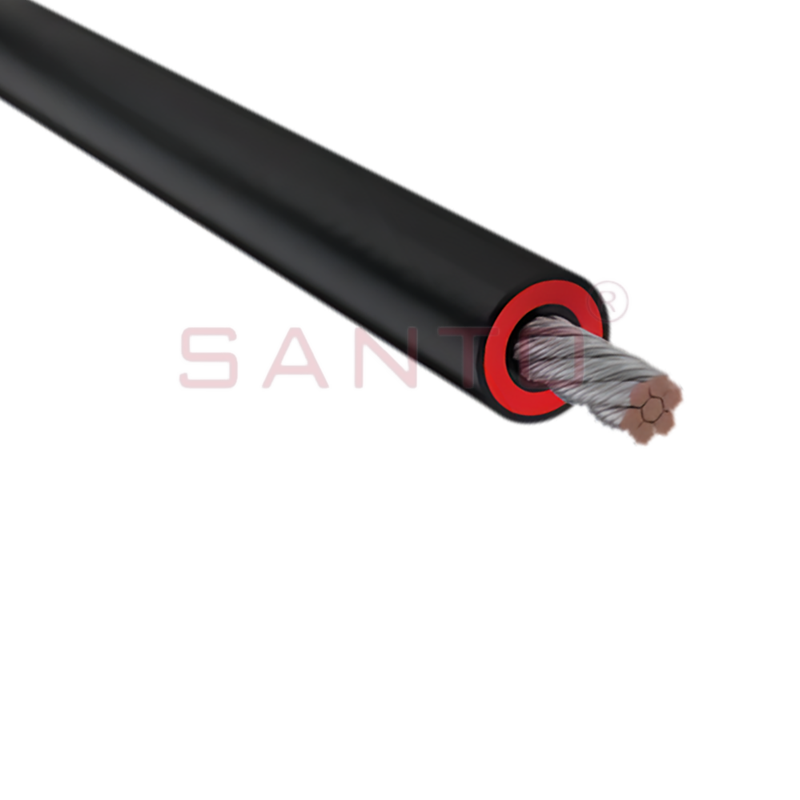
STS HV Skin-Effect Tracing Wire
The principal advantage of the STS HV Skin-Effect Tracing Wire is its ability to heat long pipelines from a single power-supply point. Traditional resistance heat-tracing circuits commonly require multiple parallel circuits when the heated length becomes large. Each circuit may need separate power distribution, junction boxes, termination assemblies, control equipment, and protective devices.
Every additional connection point introduces possible installation and maintenance requirements. On remote pipelines, underground lines, and underwater lines, access to these points may be difficult. A single-ended skin-effect system can simplify the power architecture by allowing one heating circuit to extend for a very long distance.
The system can be particularly advantageous in the following situations:
• Long transfer pipelines carrying water, chemicals, petroleum products, gas-related process materials, or other temperature-sensitive media.
• Pipelines installed in cold climates where freezing or excessive viscosity may interrupt operation.
• Underground pipelines where repeated access points are undesirable.
• Subsea or underwater pipelines where installation and maintenance are costly.
• Hazardous-area facilities where minimizing the number of electrical connections can simplify the overall design review.
• Remote industrial sites where centralized power supply and reduced field maintenance are priorities.
• Applications that require continuous temperature maintenance rather than short-term heating only.
The stated design capability of up to 30 kilometers is a major distinction compared with many ordinary electric tracing cables. Actual performance depends on the engineering design. A long circuit may require high-voltage power equipment, careful cable and tube selection, suitable protection, and detailed analysis of voltage drop, impedance, starting current, thermal expansion, and fault conditions.
The STS HV Skin-Effect Tracing Wire is intended for high-demand process heating. Its main performance characteristics include high output power, long circuit capability, single-ended supply, high operating temperature, and robust construction.
Output power can reach up to 200 watts per meter in suitable designs. The required output is determined by the pipeline diameter, process temperature, insulation thickness, ambient conditions, wind exposure, installation method, heat-loss calculation, and required warm-up time. A lower output may be sufficient for temperature maintenance, while a higher output may be selected for rapid heat-up or severe cold-weather conditions.
The system can be designed for operating temperatures up to approximately 200°C. This makes it suitable for more than simple freeze prevention. It may also support process-temperature maintenance and controlled heating of fluids whose viscosity, crystallization point, or flow characteristics must be managed.
The product information identifies intrinsic strength and reliable system design as important advantages. The heat tube provides a durable metallic enclosure around the internal conductor and can be integrated with the mechanical structure of the pipeline and insulation system. Compared with a small exposed heating wire, the tube can provide better resistance to mechanical damage during installation when properly supported and protected.
Another important characteristic is low thermal surface resistance. Since the heat tube is placed in direct thermal contact with the process pipe, the system can transfer heat efficiently. Proper clamping, contact pressure, thermal interface materials where appropriate, and continuous insulation are essential to obtain the expected performance.
| Parameter | Representative value or description |
| Heating technology | Skin effect, proximity effect, resistance heating, eddy-current loss, and hysteresis loss |
| Power-supply arrangement | Single-ended alternating-current supply |
| Maximum stated heating-line length | Up to 30 km, subject to engineering conditions |
| Maximum stated output power | Up to 200 W/m |
| Maximum stated operating temperature | Up to 200°C |
| Typical heat-tube material | Ferromagnetic carbon steel or another selected ferromagnetic alloy |
| Typical heat-tube outside diameter range | Approximately 20–60 mm |
| Typical heat-tube wall thickness | Not less than approximately 3 mm in the described design |
| Electrical safety characteristic | Very low potential at the outer surface under normal operating conditions |
| Installation environments | Above ground, underground, underwater, and selected hazardous areas |
A representative system configuration illustrates how the technology can be applied to a large pipeline. The example includes a pipeline length of 15,777 meters and a pipeline size of 273 by 7 millimeters. Polyurethane insulation with a thickness of 80 millimeters is specified, and the conveyed material is water requiring antifreeze protection.
The example uses three system parts and a total power output of 710 kVA. The supply voltage is 2,100 volts at 50 hertz, and the operating current is approximately 115 amperes. One heating element provides a rated output of 46 watts per meter. The heating tube is specified as 32 by 3.0 millimeters, while the conductor cross-sectional area is 30 square millimeters.
These figures should be understood as a project reference rather than universal product ratings. Every pipeline requires its own thermal and electrical design. The calculation must account for the actual pipeline length, fluid properties, insulation system, environmental temperature, required operating temperature, heating-up period, emergency conditions, and available power supply.
| Representative project item | Example value |
| Pipeline length | 15,777 m |
| Pipeline size | 273 × 7 mm |
| Insulation material | Polyurethane |
| Insulation thickness | 80 mm |
| Process medium | Water |
| Heating purpose | Antifreeze protection |
| System arrangement | Three-part heat-tracing system |
| Total power output | 710 kVA |
| Supply voltage | 2,100 V, 50 Hz |
| Operating current | Approximately 115 A |
| Number of heating elements | One |
| Heating output | 1 × 46 W/m |
| Heat-tube dimensions | 32 × 3.0 mm |
| Internal conductor cross-sectional area | 30 mm² |
The same project information lists an average annual temperature of approximately -5.6°C and a minimum winter temperature of approximately -48°C. Such severe conditions demonstrate why heat-loss calculations and insulation quality are critical. A system designed for a moderate climate cannot simply be transferred to an extreme cold-weather application without reviewing the required output and operating controls.
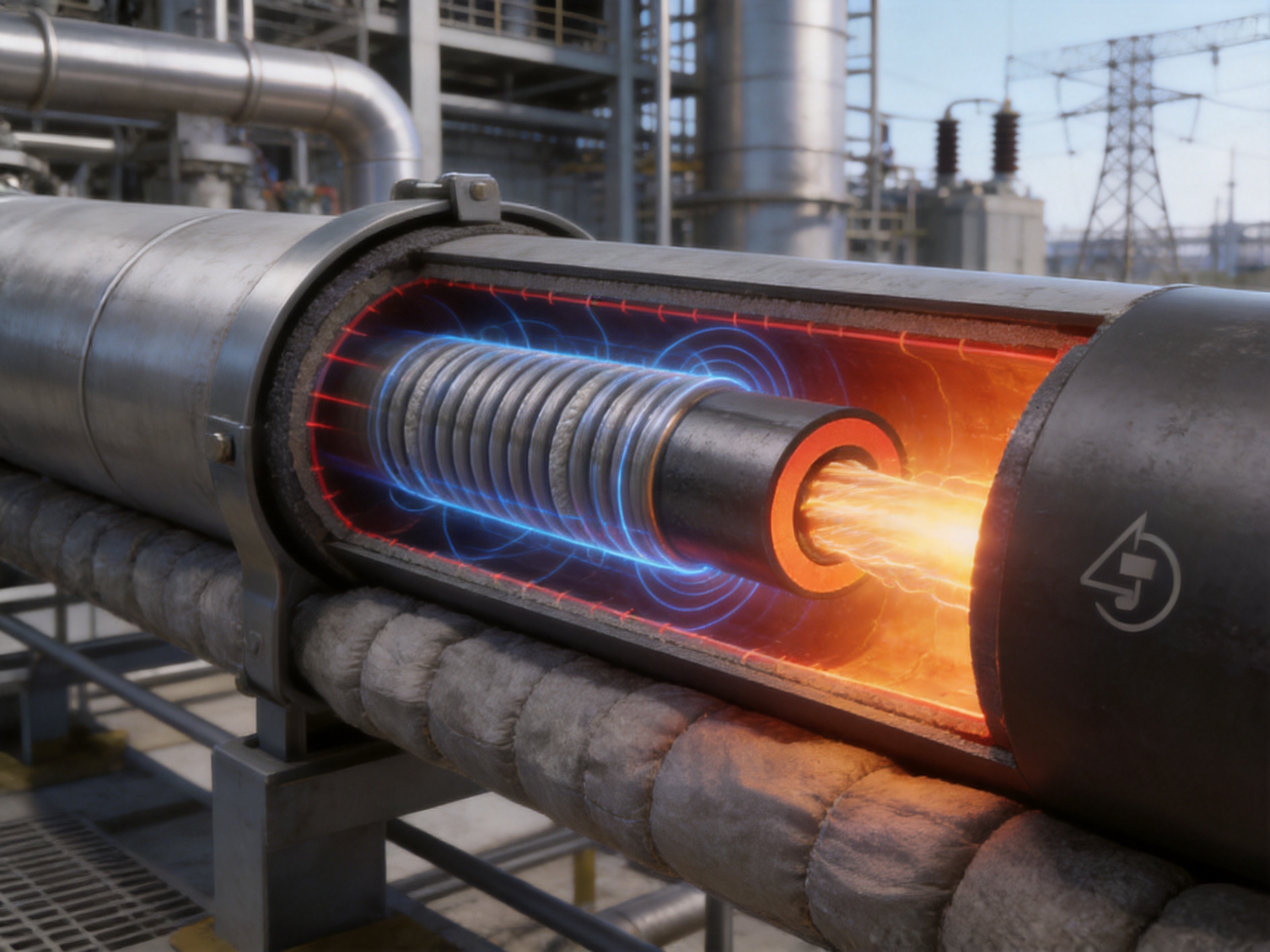
Electrical safety is a central feature of the skin-effect arrangement. The insulated conductor is enclosed within the heat tube, while the current return path is concentrated on the inside wall of the tube. Under normal operation, the external wall has little or no measurable electrical potential. This reduces the risk associated with an energized exposed heating surface.
The system may therefore be suitable for selected explosive-hazard areas, provided that the complete installation complies with the relevant hazardous-area classification, equipment certification, temperature-class requirements, earthing rules, overcurrent protection, isolation procedures, and local regulations. The heating wire alone cannot determine whether an installation is safe for a particular hazardous area. The transformer, switchgear, controls, terminations, junctions, sensors, and mechanical installation must all be evaluated as part of the complete system.
High-voltage operation requires special attention. The system may use a supply voltage significantly higher than the voltage used by ordinary low-voltage heat-tracing cables. High-voltage equipment must be installed and maintained by qualified personnel. Appropriate clearances, creepage distances, protective relays, current monitoring, insulation testing, lockout procedures, and warning systems should be incorporated into the design.
Grounding and bonding remain essential even though the outside of the heat tube is designed to have very low potential. The tube should be connected to the facility grounding and bonding system in accordance with the electrical design. The installation should also include appropriate protection against short circuits, ground faults, abnormal current, overtemperature, and loss of insulation.
Temperature sensors and control devices can be used to prevent overheating and to maintain the required process temperature. Depending on the application, control may be based on pipe-wall temperature, process temperature, ambient temperature, or a combination of these measurements. Independent high-temperature protection is recommended for critical process lines.
Conventional resistance heat-tracing cables remain useful for many applications, particularly short pipe runs, small vessels, valves, instruments, and localized freeze protection. However, their electrical and installation characteristics may become less attractive on very long pipelines.
A conventional parallel resistance cable generally has a defined maximum circuit length. As the cable becomes longer, voltage drop, power distribution, and thermal uniformity must be managed carefully. Multiple circuits may be required, each with its own power connection. A long pipeline can consequently require a large number of junctions and distribution points.
Series resistance systems can extend circuit length, but their output may be sensitive to changes in supply voltage and local resistance. A fault in one portion of the circuit may affect the entire heating length. Repairing or locating a fault can also be difficult, particularly when the cable is buried or enclosed in insulation.
Steam tracing can provide high heat output but requires a steam source, condensate return, traps, valves, and additional piping. The system may be unsuitable where steam is unavailable or where process control requires precise electrical heating. Steam systems may also involve corrosion, freezing of condensate lines, and more extensive mechanical infrastructure.
Hot-water tracing can provide uniform heating but similarly depends on a circulating fluid system, pumps, heat exchangers, and return lines. The capital and maintenance requirements may be significant for remote or widely distributed pipelines.
The skin-effect system occupies a distinct position. It combines the controllability of electrical heating with the extended circuit capability of a long metallic heating element. Its main competitive advantages include:
• Long heating lengths from a single power-supply point.
• Reduced need for parallel power-supply networks.
• Efficient use of a ferromagnetic heat tube as the main heating element.
• Low external surface potential under normal operation.
• High available output for demanding thermal applications.
• Suitability for underground and underwater installations when properly engineered.
• Strong mechanical construction and direct thermal contact with the process pipe.
• Reduced number of electrical connection points along the pipeline.
These benefits do not mean that skin-effect tracing is the best choice for every application. It is most valuable where the pipeline is long, the heat requirement is substantial, access is difficult, and a centralized power arrangement is preferred.
| Feature | Skin-effect tracing system | Typical conventional resistance cable |
| Long-distance capability | Very suitable, with designs reaching many kilometers | Often requires multiple circuits as length increases |
| Power supply | Single-ended supply is possible | Frequently uses multiple parallel supplies on long runs |
| Primary heating element | Ferromagnetic heat tube and internal conductor | Resistance heating wire or conductive polymer |
| External electrical potential | Very low at the tube exterior under normal operation | Depends on cable construction and grounding |
| Mechanical protection | Metallic tube provides robust enclosure | Depends on cable jacket and installation protection |
| Typical application strength | Long pipelines and high thermal loads | Short or medium runs and localized heating |
| Design complexity | Requires high-voltage and electromagnetic design | Usually simpler for low-voltage applications |
The performance of a skin-effect heating system depends not only on the basic operating principle but also on the accuracy and consistency of manufacturing. The heat tube, internal conductor, insulation, terminations, and accessories must work as a coordinated system. Dimensional variation, inadequate insulation, poor conductor centering, weak end connections, or inconsistent material properties can reduce system reliability.
Santo Thermal Control Technology Co., Ltd. is an electric-heating manufacturer with more than 35 years of industry experience. Its business covers research, design, production, manufacturing, and sales of electric heating and thermal-control products. The company’s product range includes self-regulating heating cables, constant-power heating cables, silicone rubber heating systems, glass-fiber heating products, mineral-insulated cables, snow-melting cables, electric heating wires, heat-tracing accessories, and related control products.
This broad product portfolio supports the development of application-specific heating systems. Pipeline heating is rarely a one-size-fits-all project. A manufacturer that understands multiple heating technologies can compare different approaches and select the most appropriate structure according to the pipe size, process medium, environment, power supply, and required temperature.
The company reports that it has strengthened new-product development, technical guidance, scientific management, product quality, and after-sales service. It also reports ISO 9001 quality-system certification and national CCC certification for its products. These certifications and management systems provide a framework for process control, documentation, inspection, traceability, and continual improvement. Project-specific certifications may still be required depending on the destination market and hazardous-area classification.
The company cooperates in product research with Harvard University in the United States and identifies itself as a high-tech enterprise in Jiangsu Province. Its development history includes the establishment of an irradiation center, the development of specialized high-temperature heating products, the creation of patented carbon-fiber parallel heating cable designs, and investment in a product simulation testing laboratory.
Its reported manufacturing and business scale includes more than 35 years of industry experience, annual output exceeding 10,000 units or product assemblies, more than 2,000 distributors, and business coverage in more than 85 areas. These figures indicate an established production and distribution network capable of supporting both standard products and customized export projects.
For a skin-effect system, material selection is particularly important because magnetic permeability, electrical resistance, wall thickness, and tube geometry influence the heating behavior. The heat tube must be manufactured with consistent dimensions and suitable metallurgical properties. The internal conductor must also have the correct cross-sectional area and insulation system for the specified voltage and temperature.
Dimensional control helps maintain a stable relationship between the internal conductor and the heat tube. This relationship affects impedance, current distribution, heating output, and dielectric stress. A stable manufacturing process can reduce variation between production batches and make system calculations more dependable.
The internal conductor requires thermally rated electrical insulation suitable for the operating voltage and temperature. The insulation must withstand manufacturing, transport, installation, and long-term thermal cycling. Electrical tests may include conductor continuity, insulation resistance, dielectric withstand, dimensional inspection, and verification of the completed termination assemblies.
For high-voltage systems, testing must be performed using controlled procedures and calibrated equipment. The test method, test voltage, duration, acceptance criteria, and documentation should be agreed during the engineering stage. Field testing after installation is also necessary because damage can occur during transportation, pulling, bending, clamping, or insulation installation.
The end termination is one of the most important components of the circuit. At the remote end, the insulated conductor must be reliably connected to the heat tube. At the power end, the conductor and tube must be connected to the correct supply and return terminals while maintaining the required insulation and mechanical protection.
Termination manufacturing requires careful preparation of contact surfaces, secure mechanical fastening or welding where specified, appropriate sealing, insulation coordination, strain relief, and protection against moisture ingress. The termination must accommodate the thermal expansion of the tube and conductor without creating excessive mechanical stress.
Complex pipeline systems benefit from simulation before production. Thermal modeling can estimate heat loss and determine the required watts per meter. Electrical modeling can calculate impedance, supply voltage, current, power factor, and protective-device requirements. Mechanical analysis can evaluate expansion, support spacing, attachment methods, and installation stresses.
A product simulation testing laboratory can support the validation of these calculations by reproducing selected operating conditions. Testing may evaluate temperature distribution, heat-up time, steady-state output, electrical behavior, surface temperature, insulation performance, and control response.
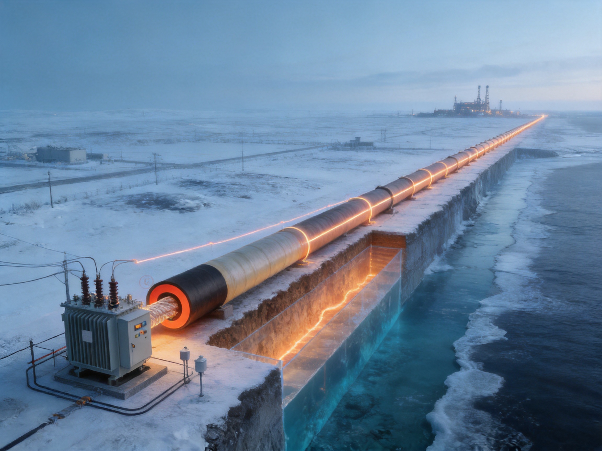
Correct installation is essential to achieving the designed performance of the STS system. The heat tube should be installed in close and continuous thermal contact with the pipeline. Gaps, uneven supports, excessive spacing, or poorly applied insulation can increase thermal resistance and cause local temperature differences.
Before installation, the pipeline surface should be inspected and prepared. Sharp edges, weld spatter, burrs, oil, moisture, and loose coatings should be removed or controlled according to the project specification. The heating tube should be routed in the approved position and secured using compatible fixing methods that will not damage the tube or interfere with thermal expansion.
The tube should not be bent below the manufacturer’s specified minimum radius. Excessive bending may distort the internal passage, damage the conductor insulation, or alter the electromagnetic relationship between the conductor and tube. Special care is required at elbows, flanges, supports, valves, expansion joints, and pipeline transitions.
The internal conductor must remain protected during installation. Pulling tension, twisting, impact, and abrasion should be controlled. The conductor should not be forced through a tube that has been deformed or contaminated. Installation records should identify circuit lengths, termination locations, test results, and any field modifications.
Thermal insulation should be installed only after the heating assembly has been inspected and tested. The insulation must be continuous around the pipe and heating tube. Moisture ingress can substantially increase heat loss and may create electrical or corrosion problems, so the vapor barrier and weatherproof outer covering must be properly sealed.
Control sensors should be positioned where they can accurately represent the pipeline condition. A sensor attached to a hot spot near the heating tube may not represent the bulk process temperature. Conversely, a sensor installed too far from the heated pipe may respond too slowly. The sensor arrangement should be selected according to the process-control philosophy.
Designing a high-voltage skin-effect tracing system involves both thermal and electrical calculations. The first step is to identify the required process condition. The designer should determine whether the application requires freeze prevention, temperature maintenance, heat-up, viscosity control, or a combination of these functions.
Thermal design should consider:
• Pipeline diameter and wall thickness.
• Process-medium freezing point, solidification point, or target viscosity.
• Desired operating and standby temperatures.
• Minimum ambient temperature.
• Wind speed and exposure for above-ground pipelines.
• Soil temperature and moisture for buried pipelines.
• Water temperature and depth for underwater pipelines.
• Insulation material, thickness, density, and moisture resistance.
• Heat losses at valves, flanges, supports, pumps, and other discontinuities.
• Required heat-up time and permissible temperature gradient.
Electrical design should consider:
• Heating-line length.
• Required watts per meter.
• Heat-tube diameter and wall thickness.
• Internal conductor cross-sectional area.
• Supply voltage and frequency.
• Circuit impedance and operating current.
• Transformer capacity and switching equipment.
• Grounding and bonding arrangements.
• Overcurrent and ground-fault protection.
• Control and monitoring architecture.
• Short-circuit and open-circuit behavior.
• Thermal expansion of the pipe, tube, and conductor assembly.
Long circuits require special attention to voltage and current distribution. The selected supply voltage must provide the required output over the complete length without exceeding the ratings of the conductor, tube, insulation, transformer, switchgear, and termination components. The system should be evaluated under normal, start-up, steady-state, and fault conditions.
For applications in hazardous areas, the design must also address area classification, equipment group, temperature class, gas or dust environment, enclosure protection, cable entries, and maintenance procedures. The complete installation should be reviewed by an appropriately qualified engineer and accepted by the responsible authority where required.
Water pipelines in cold regions may freeze when flow is interrupted or reduced. A skin-effect tracing system can maintain the water above the required minimum temperature and reduce the risk of ice formation. The representative project data describes a water pipeline with antifreeze heating requirements and severe winter temperatures.
Some petroleum products become more viscous as temperature decreases. Heating can support pumping, transfer, and stable process operation. The required temperature must be selected carefully to avoid overheating, degradation, or unsafe conditions. A high-output heating tube can provide continuous thermal support over long transfer routes.
Chemical pipelines may require temperature maintenance to prevent crystallization, solidification, phase separation, or excessive viscosity. The heat-tracing system can be integrated with process sensors and automatic controls. Material compatibility, chemical exposure, corrosion protection, and hazardous-area requirements must be considered in the design.
Gas-related facilities may require heating to prevent hydrate formation, protect measurement equipment, or maintain process conditions. Because many gas facilities are classified as hazardous areas, electrical safety and certification are essential. A low-potential external heat tube and reduced number of field connections can be valuable design features when used within an approved system.
Underground and underwater installations are difficult to access after construction. A system that can operate over a long distance from a centralized supply point can reduce the number of buried or submerged electrical connections. The mechanical design must account for installation forces, water pressure, corrosion, movement, and long-term protection of the insulation system.
Reliability begins with a complete design rather than with the heating element alone. The heat tube, conductor, terminations, power equipment, controls, sensors, insulation, and support system must all be matched to the operating environment.
The metallic heat tube provides a durable structure, but it must be protected against corrosion. The corrosion-control method may include material selection, coatings, cathodic protection, sealed insulation, drainage, and inspection. The correct approach depends on whether the pipeline is above ground, buried, or submerged.
Routine maintenance should include inspection of power equipment, control panels, termination enclosures, grounding connections, sensors, insulation jackets, and accessible sections of the heating tube. Operating current and voltage should be compared with the design values. A change in current, resistance, or temperature distribution may indicate insulation deterioration, a termination problem, moisture ingress, mechanical damage, or a control fault.
For critical pipelines, the operator may establish baseline electrical and thermal measurements during commissioning. Later measurements can be compared with the baseline to identify gradual changes. Infrared inspection may be useful on accessible insulated systems when conducted safely and when the insulation arrangement permits meaningful observation.
Maintenance personnel should use documented isolation and verification procedures before working on the system. High-voltage circuits must be de-energized, locked out, tested for absence of voltage, and grounded according to the approved safety procedure.
Long-distance heating projects generally require customization. The heating tube diameter, wall thickness, conductor size, insulation type, power rating, circuit length, termination style, and control strategy may all change from one project to another.
A suitable manufacturer should be able to support the project from initial thermal calculations through production, testing, packaging, installation guidance, commissioning, and after-sales service. Technical documentation should include product drawings, electrical data, installation instructions, inspection records, and recommended operating limits.
Customization may also include different tube materials, conductor constructions, termination arrangements, sensor layouts, control panels, and accessories. Export projects may require specific documentation, packaging standards, certifications, language requirements, and compliance with national or regional electrical codes.
The manufacturer’s experience with self-regulating, constant-power, silicone rubber, glass-fiber, mineral-insulated, snow-melting, and other electric-heating products can support a broader system-selection process. If a project includes both long pipeline sections and localized equipment, different heating technologies may be combined to achieve the most economical solution.
A dependable production process for skin-effect heating systems typically includes incoming-material inspection, tube forming or preparation, conductor production, insulation application, dimensional control, assembly, termination, electrical testing, and final documentation.
Incoming materials should be checked for chemical composition, mechanical properties, dimensions, insulation quality, and traceability. Ferromagnetic tube properties are important because they influence the electromagnetic and thermal behavior of the completed circuit.
During assembly, the internal conductor should be inserted without damaging its insulation. The conductor position should remain compatible with the approved design. Where the system uses a defined internal clearance, that clearance should be controlled throughout production.
Insulation processing should be performed under controlled conditions. Temperature, pressure, curing, irradiation, or other treatment parameters must be monitored according to the insulation technology. The company reports the establishment of an irradiation center, which can support the production of selected electric-heating products that use radiation-crosslinked insulation or related processes.
After assembly, each product should undergo inspection and testing. Typical quality checks can include:
• Visual and dimensional inspection.
• Conductor continuity and resistance measurement.
• Insulation resistance testing.
• Dielectric withstand testing.
• Termination integrity inspection.
• Tube continuity and connection verification.
• Thermal output verification where applicable.
• Marking, labeling, and traceability checks.
• Packaging and shipping inspection.
Quality management according to ISO 9001 principles helps organize these activities into controlled procedures. It also supports corrective action, supplier management, customer feedback, document control, and process improvement.
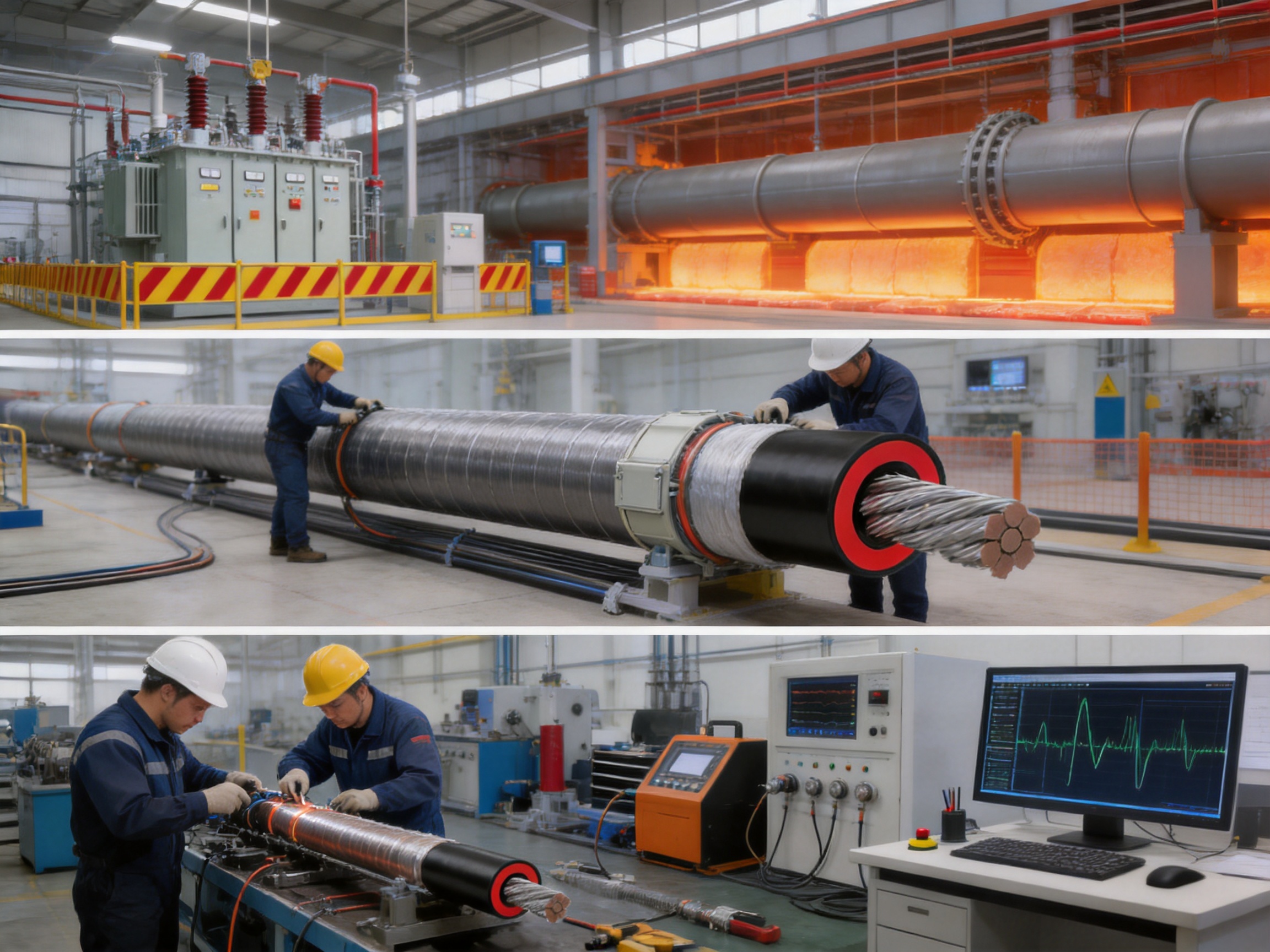
Environmental conditions strongly influence the required heating output. The representative project includes an average annual temperature of -5.6°C and a minimum winter temperature of -48°C. At such low temperatures, heat loss through insulation, supports, joints, and exposed fittings can become substantial.
For above-ground pipelines, wind can increase convective heat loss. For buried pipelines, soil temperature, moisture, depth, and thermal conductivity must be evaluated. Underwater pipelines require consideration of water movement, depth, marine corrosion, pressure, and the ability of the outer protective system to remain watertight.
Insulation must be selected not only for thermal performance but also for mechanical strength, moisture resistance, fire behavior, and compatibility with the heating temperature. Polyurethane insulation may provide efficient thermal performance, but its density, aging behavior, vapor protection, and temperature rating must be confirmed for the intended project.
The heating system should be designed with enough capacity to meet the worst credible operating condition, but excessive output can increase energy consumption and create temperature-control challenges. A properly designed control system can reduce energy use by energizing the circuit only when heating is required or by modulating the effective output according to the process temperature.
The economic value of a long-distance skin-effect system comes from the combination of thermal efficiency, simplified power distribution, reduced connection count, and reduced maintenance access requirements. The total project cost should be evaluated over the entire service life rather than by comparing only the initial price of the heating cable.
A single-ended supply arrangement can reduce the amount of parallel electrical infrastructure required along the route. Fewer junctions may reduce installation labor and the number of potential failure points. In remote locations, avoiding additional power stations or access structures can produce significant savings.
Heat-transfer efficiency also affects operating cost. The heat tube is attached directly to the process pipe and enclosed within the insulation system, which helps direct heat toward the process. Good insulation design and accurate control are necessary to achieve the expected energy performance.
The best economic result is achieved when the system is correctly sized. Oversizing may waste energy, while undersizing may fail to maintain the required process temperature. Thermal modeling, field conditions, operating history, and process requirements should therefore be used to establish the design output.
Before selecting an STS HV Skin-Effect Tracing Wire system, the project team should prepare a complete technical schedule. The schedule should include the following information:
1. Total pipeline length and the length of each heating circuit.
2. Pipe outside diameter, wall thickness, material, and surface condition.
3. Process medium and its freezing, crystallization, or target-temperature requirements.
4. Minimum and maximum ambient conditions.
5. Above-ground, underground, or underwater installation method.
6. Insulation material, thickness, density, and weatherproofing.
7. Required operating temperature and heat-up time.
8. Available supply voltage, frequency, and transformer capacity.
9. Hazardous-area classification and certification requirements.
10. Control, monitoring, alarm, and communication requirements.
11. Required tube dimensions, conductor size, and termination arrangement.
12. Applicable standards, inspection requirements, and documentation.
The manufacturer can then determine whether a skin-effect system is appropriate and calculate the suitable heating output and electrical arrangement. A technical review should confirm the expected operating current, voltage, thermal profile, circuit impedance, protective-device settings, and installation method before production begins.
It is a high-voltage pipeline heating system consisting of an insulated conductor installed inside a ferromagnetic heat tube. Alternating current flows through the conductor and returns through the inner surface of the tube, producing heat through skin effect, proximity effect, electrical resistance, eddy currents, and magnetic hysteresis.
The stated system capability can reach up to 30 kilometers. The actual maximum length depends on the tube and conductor design, output requirement, supply voltage, current, transformer capacity, environmental conditions, and project-specific electrical calculations.
One of its main advantages is the ability to use a single-ended power supply. This can reduce the need for parallel power distribution along a long pipeline. The final arrangement must still be determined by the electrical design and the required heating length.
The stated maximum output can reach up to 200 watts per meter in suitable designs. The selected output should be based on calculated heat loss and process requirements rather than on the maximum rating alone.
The stated operating temperature can reach up to approximately 200°C. The permissible temperature depends on the insulation, conductor, heat tube, termination, controls, pipeline materials, and complete system design.
It can be used in selected explosive-hazard areas when the complete system is designed, certified, installed, and maintained according to the applicable hazardous-area requirements. The heating element by itself does not establish compliance. Power equipment, controls, terminations, grounding, temperature class, and protection must also be evaluated.
Ferromagnetic material has magnetic properties that intensify the skin effect and support additional heating through eddy currents and hysteresis. This allows the tube to serve as the principal heating element and improves the effectiveness of the long-distance circuit.
Under normal operating conditions, the current is concentrated mainly on the inner surface of the tube, and the external surface has very low measurable potential. Proper grounding, bonding, insulation coordination, and testing are still required.
Yes. Freeze prevention and antifreeze protection are among the intended applications. The required output must be calculated from the minimum ambient temperature, pipe dimensions, process medium, insulation, wind, and operating conditions.
Yes. The representative project information describes a water pipeline with antifreeze heating requirements. The system may also be used for other process fluids when the temperature and material requirements are compatible.
The insulation type and thickness depend on the thermal design. Polyurethane insulation is identified in the representative project, but other materials may be suitable. The selected insulation must meet the project’s thermal, mechanical, fire, moisture, and temperature requirements.
Maintenance may include checking the power equipment, current, voltage, controls, sensors, grounding, termination enclosures, insulation condition, and accessible sections of the heating assembly. High-voltage isolation and safety procedures must be followed before inspection or repair.
Yes. Long-distance pipeline heating systems are normally customized. Tube size, conductor area, insulation, heating output, supply voltage, circuit length, terminations, controls, and accessories can be selected according to the project design.
A quotation request should include pipeline length, pipe size, process medium, target temperature, minimum ambient temperature, insulation details, installation environment, available power supply, hazardous-area requirements, and desired control method. Drawings and operating conditions are also helpful.
The main difference is the use of a ferromagnetic heat tube and a single-ended alternating-current circuit. The tube becomes the primary heating element, allowing very long heating circuits and a low-potential outer surface. Ordinary heating cable is often better suited to shorter runs or localized heating.
The STS HV Skin-Effect Tracing Wire provides a specialized solution for long-distance pipeline heating where conventional electric tracing may require too many parallel circuits or connection points. Its ferromagnetic heat tube uses skin effect, proximity effect, resistance, eddy currents, and hysteresis to generate heat efficiently along the pipeline.
The system’s key advantages include heating lengths that can reach up to 30 kilometers, single-ended power supply, output power up to 200 watts per meter, operating temperatures up to approximately 200°C, low external surface potential, mechanical strength, and suitability for demanding above-ground, underground, underwater, and selected hazardous-area applications.
Its success depends on professional engineering. Thermal calculations, electrical design, high-voltage protection, hazardous-area compliance, grounding, termination quality, insulation, installation, and commissioning must all be addressed as part of the complete system.
Santo Thermal Control Technology Co., Ltd. combines electric-heating product development, manufacturing experience, quality management, testing capability, and international supply experience. Its broader product portfolio and investment in product development and simulation testing support customized heating solutions for industrial users.
For pipeline operators seeking a reliable and economical method of maintaining process temperature over long distances, a properly designed skin-effect tracing system can provide a strong alternative to conventional resistance cables, steam tracing, and hot-water tracing. With the correct specification and installation, it can improve thermal continuity, simplify power distribution, and support dependable operation in challenging environments.
1. Product technical information for STS HV Skin-Effect Tracing Wire.
2. Introduction to Skin-Effect Tracing System, technical document.
3. Skin-Effect Tracing System Technology, application document.
4. Skin-Effect Tracing System Product Datasheets.
5. General principles of alternating-current skin effect and proximity effect in ferromagnetic conductors.
6. General engineering practices for electric heat tracing, pipeline thermal insulation, grounding, and hazardous-area equipment.
7. Quality-management principles based on ISO 9001 requirements.
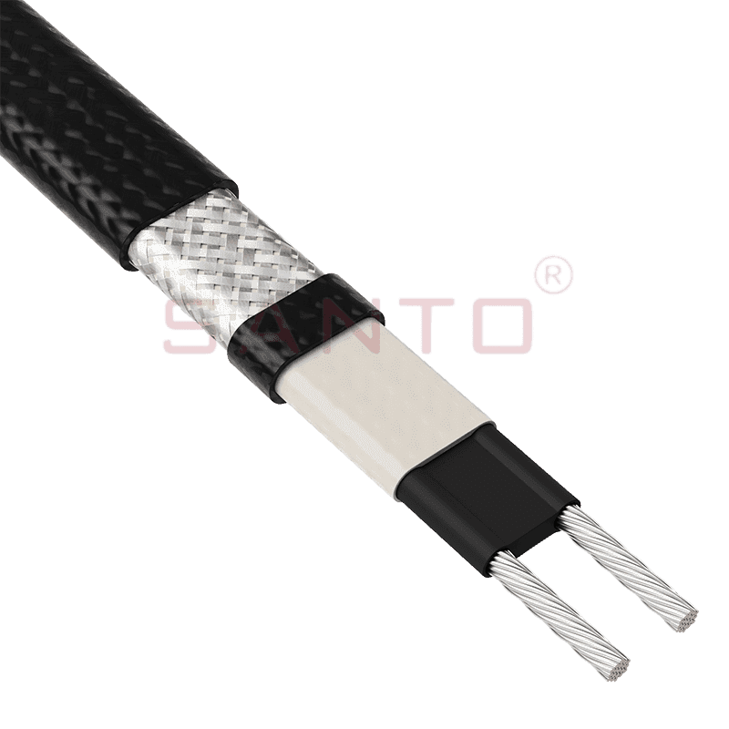
The SANTO UFA range of self-regulating heating cables is mainly used for frost protection of pipes and vessels but can also be used to maintain processes up to 65°C. These heating cables are available...
See Details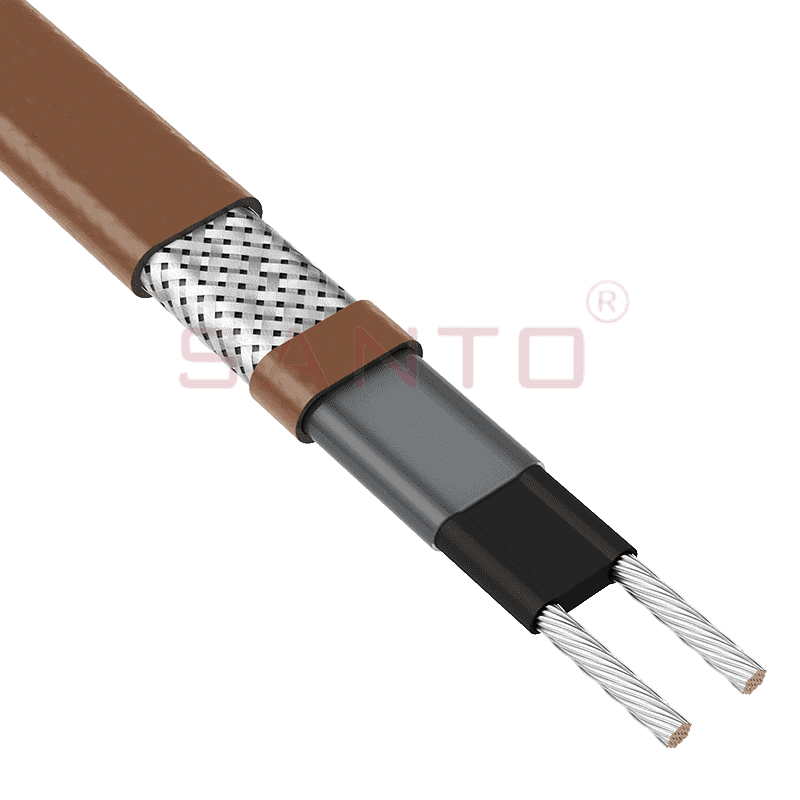
The SANTO UFB range of self-regulating heating cables is mainly used for frost protection of pipes and vessels requiring a higher power output than the UFA heating cables can supply. They can also be ...
See Details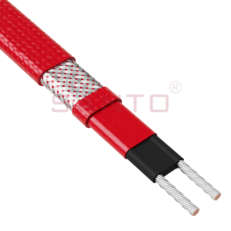
The SANTO UFC range of self-regulating heating cables is used for frost protection of pipes and vessels that require steam cleaning. They can also be used to maintain processes up to 121°C. These heat...
See Details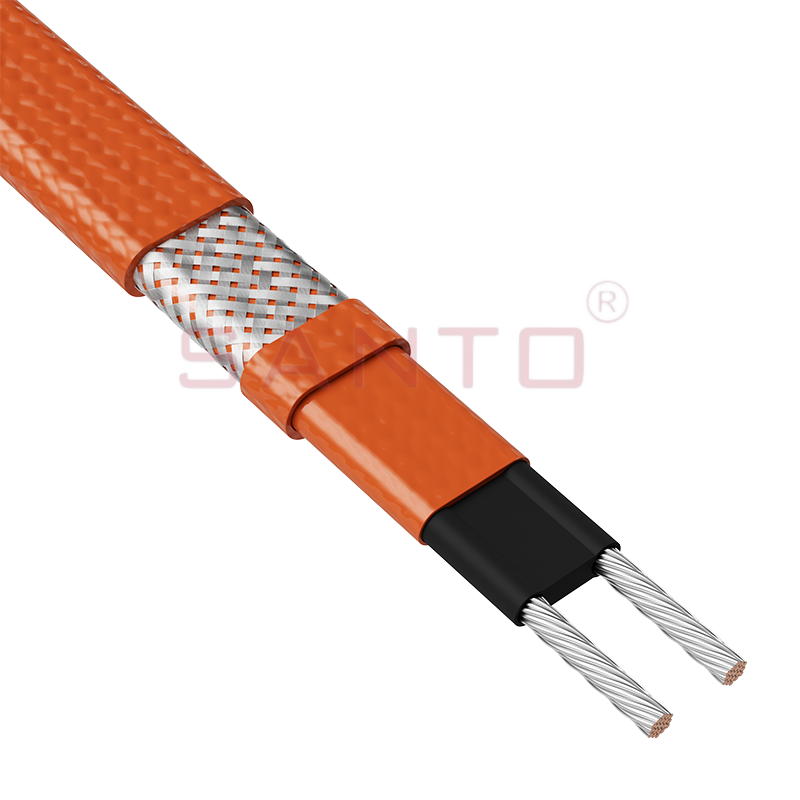
The SANTO UFO range of self-regulating heating cables is mainly used for frost protection of pipes and vessels that require steam cleaning . They can also be used to maintain processes up to 150°C. Th...
See Details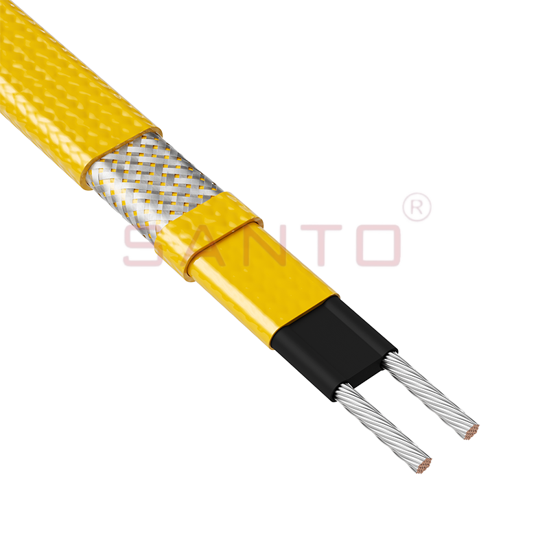
The SANTO UFD series of self-regulating heating cables are mainly used for freeze protection of pipes and vessels, but can also be used to maintain processes up to 200°C. These heating cables are avai...
See Details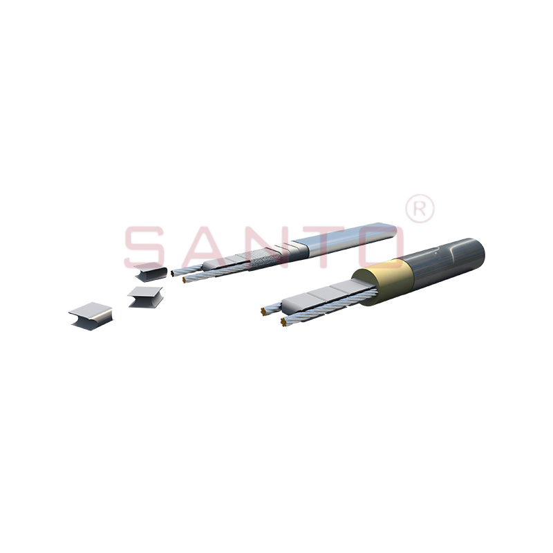
SANTO UFY heating wire is suitable for applications that maintain process temperatures up to 260 ℃ and can be steam blown; The self-regulating and parallel circuit heating wires of the UFY series are ...
See Details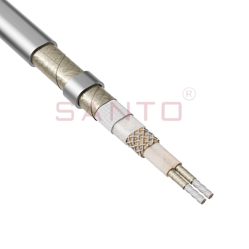
The SANTO UFM series self-regulating heating cables are mainly used for freeze protection of pipes and vessels, but can also be used to maintain processes up to 400°C. These heating cables are availab...
See Details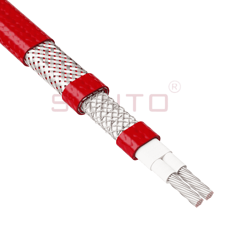
The SANTO ACC range of power-limiting heating cables is mainly used for temperature maintenance of processes and offers the advantage of a high power output at high temperatures which can reduce the n...
See Details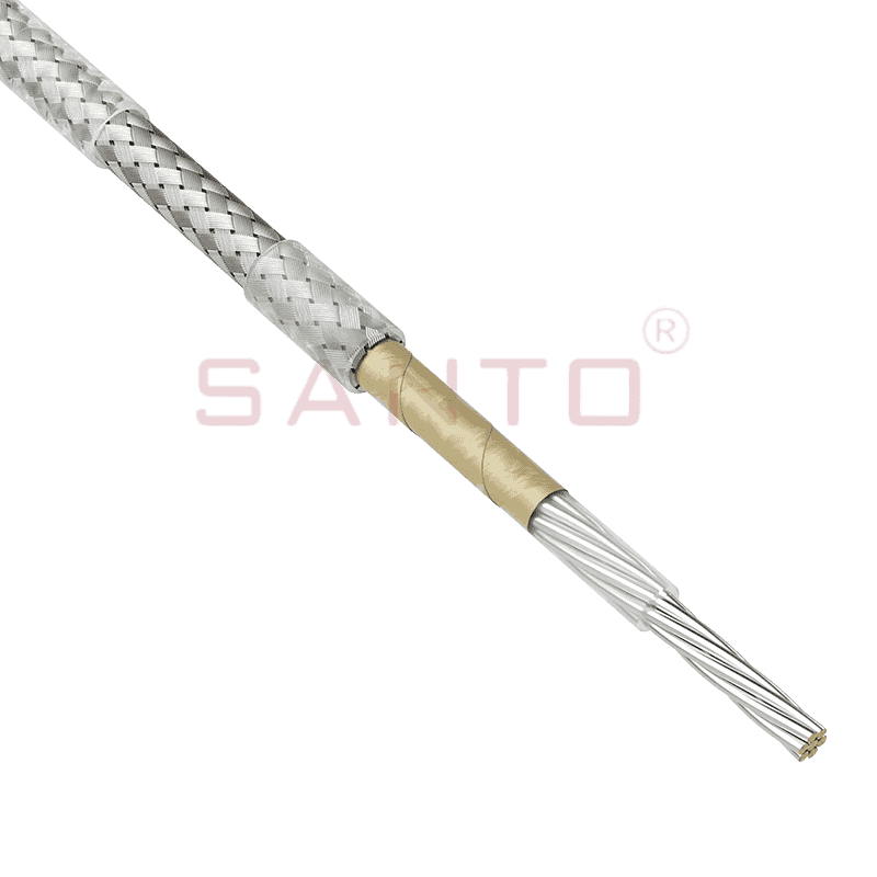
The stranded high temperature conductor is nickel plated to ensure a long life at elevated temperatures in corrosive environments. It is electrically isolated using an innovative sandwich construction...
See Details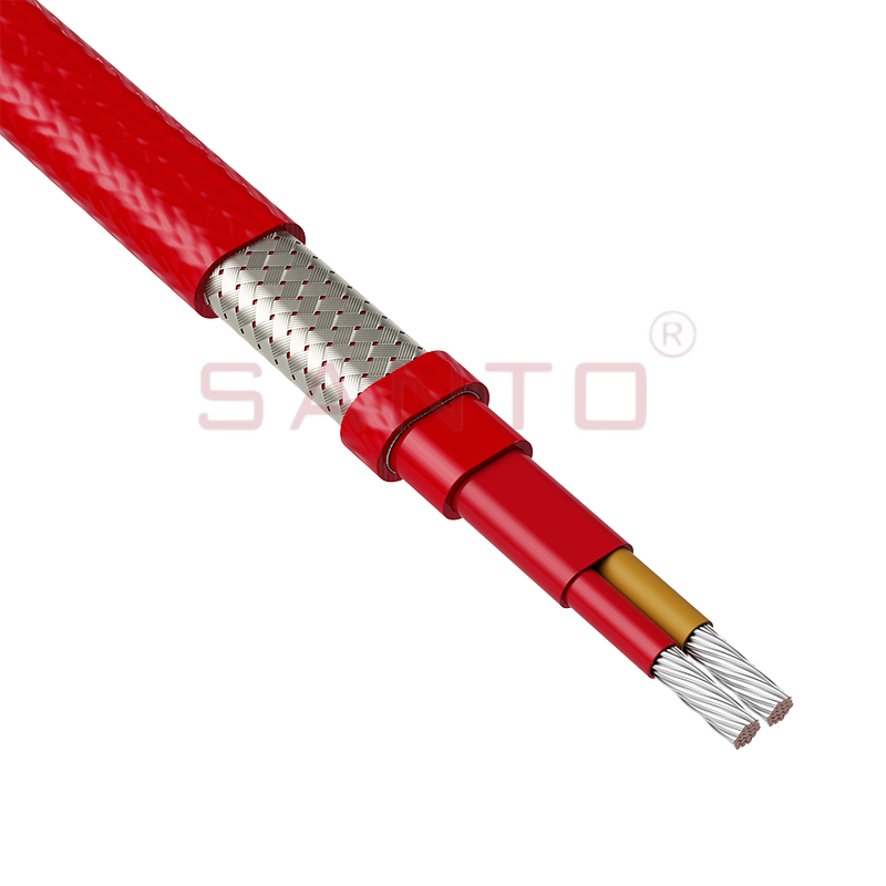
The stranded high temperature conductor is nickel plated to ensure a long life at elevated temperatures in corrosive environments. It is electrically isolated using an innovative sandwich construction...
See Details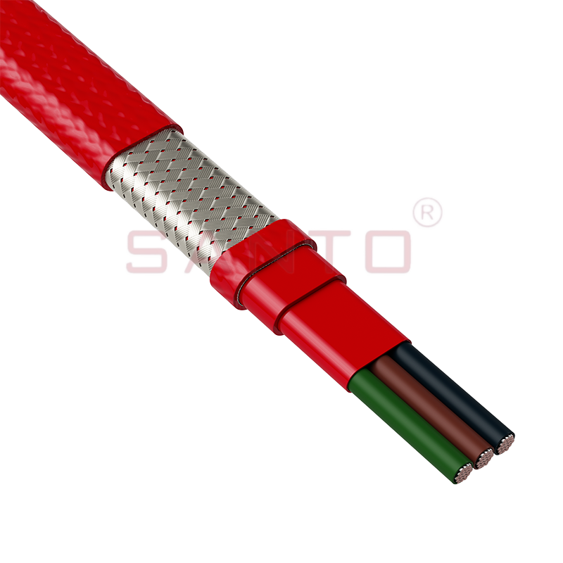
The stranded high temperature conductor is nickel plated to ensure a long life at elevated temperatures in corrosive environments. It is electrically isolated using an innovative sandwich construction...
See Details
SANTO HAx mineral insulated (MI) Alloy 825 series heating cables are suitable for use in hazardous areas. They have been designed for use in freeze protection and temperature maintenance applications ...
See Details
Santo electric heating strips are widely used in key industries in China.

