 English
 English
 русский
 日本語
 Español
 中文简体

The SANTO UFA range of self-regulating heating cables is mainly used for frost protection of pipes and vessels but can also be used to maintain processes up to 65°C. These heating cables are available...
See Details
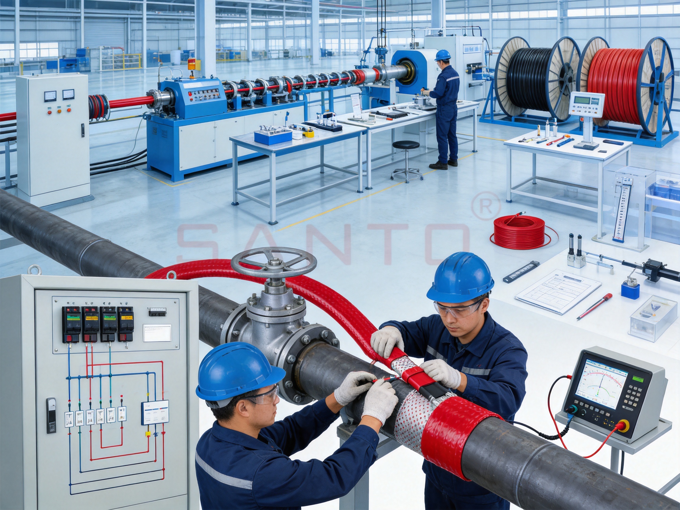
Self-regulating heat tracing is an important technology for protecting pipes, vessels, process lines, valves, and instruments from freezing and for maintaining the temperature of industrial fluids. Unlike ordinary fixed-output heating elements, a self-regulating cable automatically adjusts its heat output in response to the temperature surrounding the cable. It produces more heat when the installation is cold and reduces its output as the temperature rises. This operating principle helps improve energy efficiency, simplify temperature control, and reduce the risk of overheating.
The UFC range of self-regulating heat tracing cables is designed for demanding industrial applications where ordinary polymer-jacketed heating cables may not provide adequate chemical resistance or environmental durability. Its fluoropolymer outer jacket supports use in contact with many organic and corrosive substances, while the product range is intended for frost protection and process temperature maintenance up to 121°C under suitable design conditions. The cables are also designed for use in hazardous areas, including gas and dust zones, when installed according to the applicable certification, electrical protection, and installation requirements.
This article explains the construction, operating principle, technical characteristics, application advantages, installation considerations, manufacturing strengths, and selection process associated with UFC self-regulating heat tracing cables. It also compares the technology with several common alternatives and answers frequently asked questions from engineers, contractors, plant operators, and purchasing teams.
Content
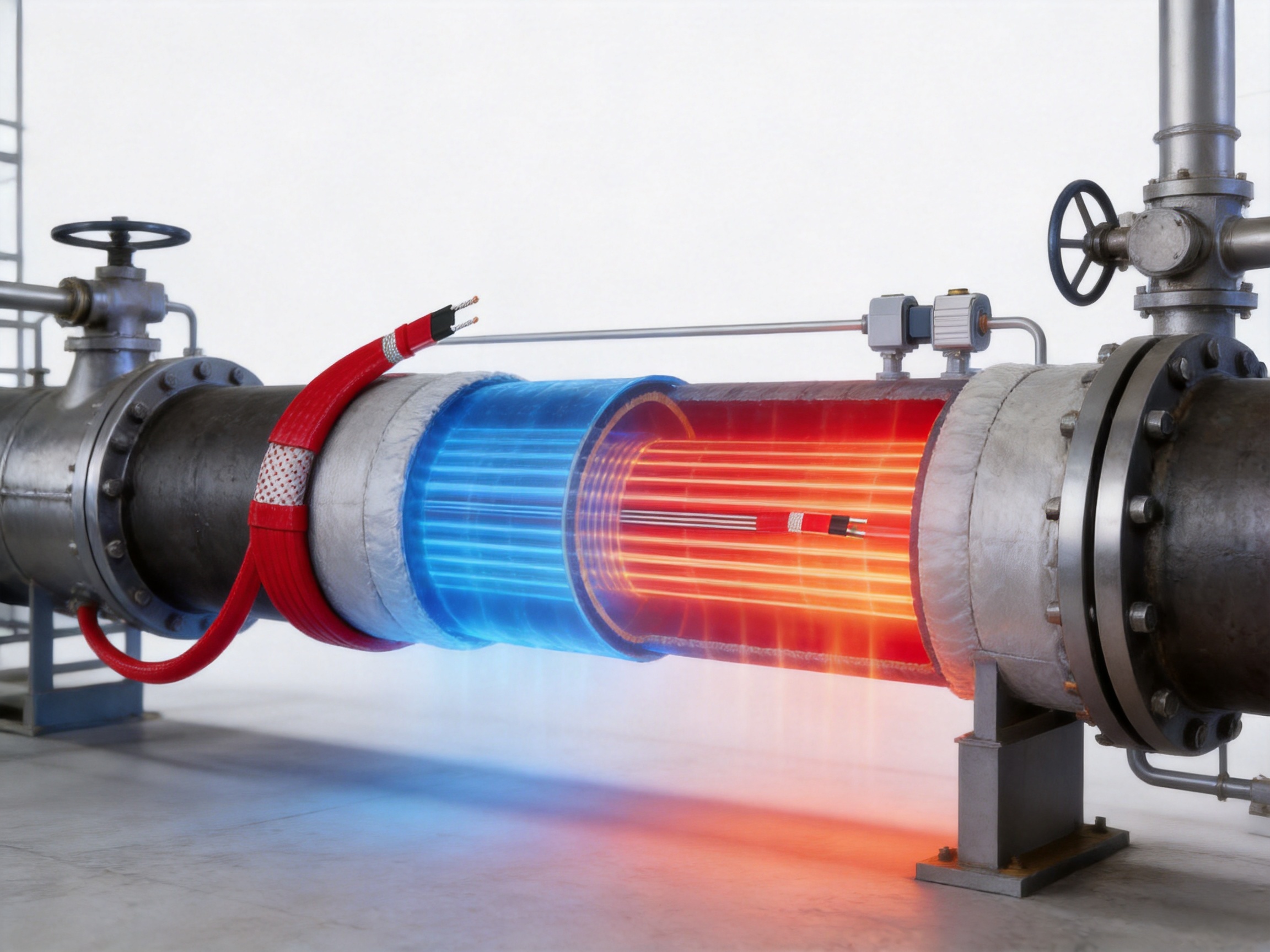
UFC self-regulating heating cables are parallel-circuit heat tracing products. Their construction includes conductive bus wires and a temperature-responsive polymer core. As the surrounding temperature changes, the electrical characteristics of the core change as well. When the cable is cold, the core allows a higher current flow and produces greater heat. When the cable becomes warmer, the core expands electrically and restricts current flow, lowering the heat output.
This behavior occurs continuously along the cable. A section installed on a cold area of pipe can produce more heat than another section installed on a warmer area of the same pipe. The cable therefore responds locally rather than treating the entire circuit as a single uniform heating element. This is particularly valuable on pipe systems with changing ambient conditions, heat sinks, supports, valves, flanges, and different insulation conditions.
The UFC range is principally intended for frost protection of pipes and vessels that require steam cleaning. It can also be used to maintain industrial processes up to 121°C, subject to the specified cable type, design temperature, insulation system, control method, and hazardous-area requirements. The fluoropolymer jacket provides a higher level of resistance to chemical exposure than many conventional thermoplastic outer jackets.
Available voltage options listed for the range include 24 Vac, 36 Vac, 110 Vac, 230 Vac, and 400 Vac. This broad voltage selection allows the cable to be matched with different control panels, distribution systems, and site electrical standards. The final voltage selection must always be confirmed against the product specification, circuit length, starting temperature, protective device, and local electrical regulations.
| Product characteristic | UFC range information |
|---|---|
| Heating technology | Self-regulating parallel-circuit heating cable |
| Primary applications | Pipe and vessel frost protection, steam-cleaned systems, and process temperature maintenance |
| Process maintenance capability | Applications up to 121°C under suitable design conditions |
| Outer jacket | Fluoropolymer, selected for high chemical resistance |
| Nominal voltage options | 24 Vac, 36 Vac, 110 Vac, 230 Vac, and 400 Vac |
| Minimum installation temperature | -60°C |
| Hazardous-area suitability | Zone 1, Zone 2 gas, Zone 21 dust, and Zone 22 dust applications when properly certified and installed |
| Temperature classification | T3 for listed UFC types, with 20UFC-CT identified separately as T2 in the supplied data |
The central component of a self-regulating cable is its temperature-sensitive conductive matrix. The matrix is positioned between parallel electrical conductors. At low temperatures, the matrix contains many effective current paths, allowing the cable to produce a relatively high output. As the matrix warms, molecular movement changes the number and effectiveness of those current paths. The electrical resistance increases, and the output decreases.
Self-regulation does not mean that the cable operates without electrical protection or system controls. A complete heat tracing system still requires appropriate circuit breakers, residual-current protection, termination kits, connection accessories, support methods, insulation, and, where required, thermostatic or electronic control. Self-regulation reduces the likelihood of overheating caused by local hot spots, but it does not replace engineering design or safe installation practices.
A major benefit of the parallel-circuit construction is that the cable can generally be cut to the required length in the field, provided that the cable is terminated correctly and the maximum circuit length is not exceeded. This can simplify installation around complex pipe routes. It also makes the cable suitable for a wide range of line lengths and configurations, although every cut end must be sealed using approved components.
The output of a self-regulating cable is influenced by the surrounding temperature, the pipe material, insulation quality, supply voltage, installation arrangement, and the presence of heat sinks. The published output values are therefore reference values at a specified temperature rather than a constant heat rating under all operating conditions.
One of the most significant advantages of the UFC range is its fluoropolymer outer jacket. Industrial heat tracing may be exposed to hydrocarbons, solvents, cleaning chemicals, process fluids, corrosive vapors, oils, and outdoor contaminants. A cable jacket that performs well in a general utility area may deteriorate when continuously exposed to aggressive chemicals or repeated washdown procedures.
Fluoropolymers are widely recognized for their chemical resistance, low moisture absorption, stable electrical insulation characteristics, and useful temperature performance. By using a fluoropolymer outer jacket, the UFC cable is better suited to applications where ordinary thermoplastic materials may become brittle, swell, crack, or lose mechanical integrity.
The supplied application information identifies compatibility with carbon steel, stainless steel, plastic-coated surfaces, and unpainted metal. It also refers to organic and corrosive substances. However, chemical compatibility depends on the exact chemical, concentration, temperature, exposure duration, pressure, cleaning method, and mechanical conditions. For aggressive organic or corrosive substances, the application should be reviewed by a qualified technical representative before the cable is selected.
The jacket is especially useful in facilities that require routine cleaning or steam cleaning. Such environments can combine chemical exposure with rapid temperature changes, moisture, mechanical handling, and pressure from cleaning equipment. The heating cable must be designed not only for normal operation but also for the maximum exposure temperature and cumulative exposure time associated with cleaning cycles.
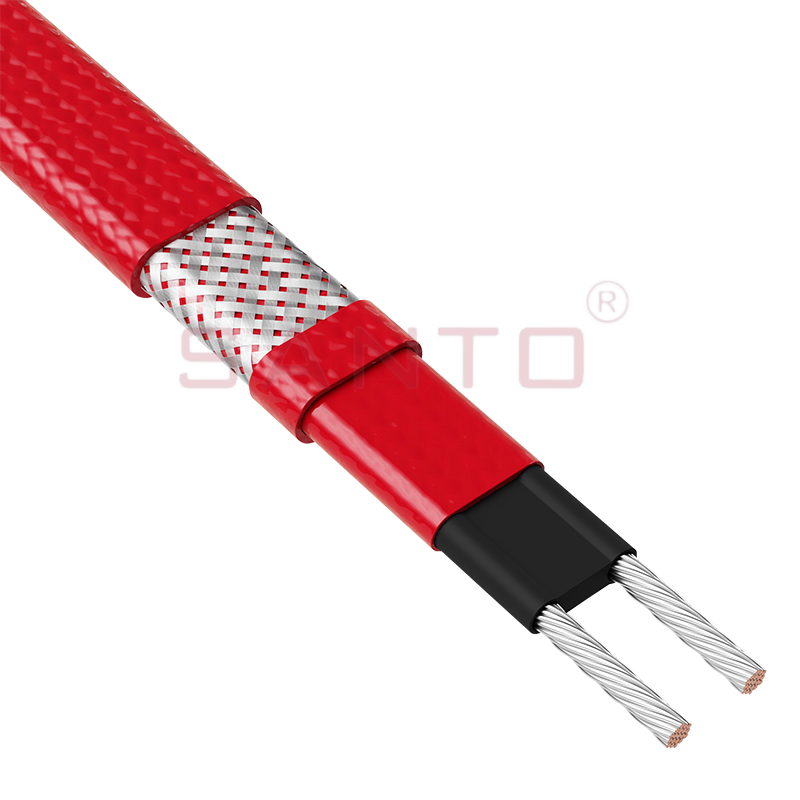
UFC Self-Regulating Heat Tracing Cables
Steam cleaning creates a difficult operating profile for any electrical heating product. During normal operation, the cable may be energized to prevent freezing or maintain a process temperature. During cleaning, it may be exposed to hot saturated steam, elevated pressure, condensation, and mechanical movement caused by thermal expansion. A product intended for this service must be selected with careful attention to energized and de-energized exposure conditions.
The supplied technical information states a maximum exposure temperature of 70°C when continuously energized. It also identifies an intermittent power-supply exposure condition of 215°C associated with 20 bar saturated steam, with a maximum cumulative exposure time of 1,000 hours. These figures must be interpreted as design limitations rather than general permission to operate continuously at those temperatures.
Where steam cleaning is part of the process, the heating circuit may need to be switched off during the cleaning cycle. The installer and plant operator should establish a documented operating procedure that coordinates steam supply, cable energization, circuit isolation, and post-cleaning inspection. Automatic interlocking may be appropriate where accidental energization during a high-temperature cleaning cycle could exceed the cable’s continuous exposure rating.
The cable’s fluoropolymer jacket provides an additional layer of protection against chemical and environmental stress, but the complete system also depends on the quality of end seals, connection kits, junction boxes, gland entries, and insulation. A chemically resistant cable can still fail if an incompatible accessory is used or if moisture enters through an improperly installed termination.
For this reason, steam-cleaning applications should be evaluated as complete systems. The cable length, circuit arrangement, cable attachment method, thermal insulation, control panel, hazardous-area equipment, and operating schedule should all be considered together.
The UFC heating lines are identified as suitable for hazardous areas including Zone 1 and Zone 2 gas environments and Zone 21 and Zone 22 dust environments, subject to the applicable certification and installation conditions. These classifications are relevant to facilities where flammable gases, vapors, or combustible dust may be present during normal operation or under abnormal conditions.
Hazardous-area heat tracing requires more than selecting a cable with an appropriate temperature classification. The complete installation must comply with the applicable explosion-protection standards and site rules. This includes cable construction, end termination, junction boxes, glands, control devices, circuit protection, equipotential bonding, temperature limitation, and inspection procedures.
The supplied information refers to European Standard EN 60079-30-1 and identifies an absolute temperature classification of T3 for several UFC models, with 20UFC-CT shown separately as T2. Temperature classification is important because the maximum surface temperature of the heating system must remain below the ignition temperature of the hazardous atmosphere. The lower the permitted ignition temperature, the more carefully the system must be controlled and assessed.
The applicable certification should be verified for the exact model and installation arrangement. Engineers should not assume that certification for one cable type automatically applies to another type, voltage, accessory, or installation method. The equipment marking, certificate, design temperature, and local hazardous-area requirements must be reviewed before procurement and commissioning.
In a hazardous area, a residual-current device or earth-leakage protection device is particularly important. The supplied information recommends a 30 mA leakage protection device for maximum safety and fire prevention. Applications with high leakage current may require a device rated up to 300 mA, subject to the applicable regulations and a documented safety assessment. Protection settings must not be selected solely on the basis of convenience; they must be coordinated with cable length, insulation resistance, startup current, and the electrical distribution system.
The listed UFC range includes 4UFC-CT, 8UFC-CT, 12UFC-CT, 15UFC-CT, and 20UFC-CT models. The supplied performance table identifies reference output values at 10°C as 13 W/m, 26 W/m, 40 W/m, 50 W/m, and 66 W/m respectively. These values provide a practical basis for selecting a cable according to the calculated heat loss of the pipe or vessel.
| Model | Reference output at 10°C | Approximate thickness | Approximate width | Approximate weight |
|---|---|---|---|---|
| 4UFC-CT | 13 W/m | 4.5 mm | 12.5 mm | 130 g/m |
| 8UFC-CT | 26 W/m | 4.5 mm | 12.5 mm | 130 g/m |
| 12UFC-CT | 40 W/m | 4.8 mm | 12.5 mm | 130 g/m |
| 15UFC-CT | 50 W/m | 4.8 mm | 12.5 mm | 130 g/m |
| 20UFC-CT | 66 W/m | 4.8 mm | 12.5 mm | 130 g/m |
The model number should not be used as the only selection criterion. A proper design begins with the required maintenance temperature, minimum ambient temperature, pipe diameter, insulation type and thickness, wind exposure, operating conditions, heat sink allowance, voltage, circuit length, and hazardous-area classification.
A low-output cable may be appropriate for frost protection on a well-insulated indoor pipe. A higher-output cable may be needed for a large outdoor pipe, a process line with a high maintenance temperature, or a vessel with substantial heat loss. However, using a higher-output product does not automatically improve the system. Excessive output may create unnecessary energy consumption, complicate temperature limitation, or exceed the permissible temperature of the process, insulation, or hazardous-area installation.
Self-regulating technology offers an advantage because its output reduces as the cable becomes warmer. Even so, the highest local temperature, the design surface temperature, and the process sensitivity must be considered. Temperature control may be recommended or required for processes where the permitted temperature range is narrow.
The supplied circuit-length information is based on IEC 60898-compliant Type C circuit breakers. It provides estimated maximum heating wire lengths for several protective device ratings and two conductor cross-sectional areas identified as 1.2 mm² and 2.5 mm² in the source data. Because the original table formatting combines headings and model columns, the exact application of each value should be verified against the current product specification before final design.
| Protective device | Starting temperature | Indicative maximum lengths across the listed UFC models |
|---|---|---|
| 16 A, Type C | -20°C | Approximately 40 to 145 m, depending on cable model and conductor arrangement |
| 16 A, Type C | +10°C | Approximately 45 to 170 m, depending on cable model and conductor arrangement |
| 25 A, Type C | -20°C | Approximately 65 to 225 m, depending on cable model and conductor arrangement |
| 25 A, Type C | +10°C | Approximately 70 to 245 m, depending on cable model and conductor arrangement |
| 32 A, Type C | -20°C | Approximately 80 to 245 m, depending on cable model and conductor arrangement |
| 40 A, Type C | -20°C or +10°C | Approximately 105 to 245 m, depending on cable model and conductor arrangement |
These values are intended for estimation rather than final approval. Starting current can be significantly higher at low ambient temperature because a self-regulating cable produces more heat when cold. This effect must be considered when choosing the circuit breaker and calculating the maximum circuit length.
Voltage drop, inrush behavior, earth leakage, conductor size, ambient temperature, installation grouping, and prospective short-circuit current can also affect the final electrical design. Where a long circuit is required, dividing the trace into multiple circuits may improve reliability and simplify fault location. Each circuit should be independently protected and labeled.
The recommendation for residual-current protection is an important part of system safety. A 30 mA device is identified for maximum safety and fire prevention. Where cable capacitance or environmental conditions create higher normal leakage, a higher-rated device may be considered only after assessment by a qualified electrical engineer. Leakage protection must not be bypassed simply to prevent nuisance tripping.
The minimum installation temperature for the UFC range is listed as -60°C. This allows installation in very cold environments, provided that the cable is handled carefully and the selected accessory system remains suitable for the same conditions.
Cold-weather installation requires special attention because polymeric materials become less flexible at low temperatures. The supplied bend-radius data identifies approximately 13 mm at 20°C and 51 mm at -60°C. The larger bend radius at very low temperatures helps prevent excessive mechanical stress on the cable core, jacket, and electrical conductors.
The heating cable should not be folded, sharply creased, twisted, or pulled around corners tighter than the specified minimum radius. Sharp bends are particularly dangerous near valves, supports, flanges, and connection points. When installing in cold weather, the cable should be uncoiled gradually and protected from impact or crushing.
Before installation, the route should be inspected for burrs, sharp edges, welding spatter, oil contamination, and other conditions that could damage the jacket. Cable attachment materials should be compatible with the pipe surface and should not cut into the fluoropolymer jacket. Metal bands, if used, must be selected and applied carefully to avoid excessive pressure.
The cable should generally be positioned to provide good thermal contact with the pipe. On horizontal pipes, the preferred position may depend on the application, insulation design, drainage conditions, and heat-loss calculation. Additional cable may be required at valves, flanges, supports, pumps, strainers, and other heat sinks. These additional lengths should be included in circuit calculations.
The UFC range is identified for use on carbon steel, stainless steel, plastic-coated surfaces, and unpainted metal. This flexibility is important because industrial facilities commonly combine different pipe materials within the same process unit.
Carbon steel is common in general industrial and energy applications, but it can have a rougher surface and may require corrosion protection. Stainless steel is widely used for hygienic, chemical, and corrosive services, but its thermal conductivity and surface finish may differ from carbon steel. Plastic-coated pipes can be more sensitive to local temperature and mechanical pressure, so the cable output and surface-temperature limitation must be assessed carefully.
For unpainted metal, the installer should confirm that the surface is clean, dry, and free from sharp projections. If a protective coating is applied later, the compatibility of the coating with the cable jacket and the expected operating temperature should be verified. The cable must not be buried under a coating or covering that prevents inspection or creates an unapproved thermal condition.
Vessels and tanks often require a different layout from straight pipe. The cable may be installed in parallel runs, spiral patterns, or selected zones depending on the heat-loss calculation. Vessel nozzles, manways, brackets, legs, and support points can act as heat sinks. The design should ensure that the required heat is delivered uniformly without creating excessive temperature at any localized point.
Constant-wattage cable produces substantially the same output along its active length. It can provide predictable heat, but a thermostat or controller is often needed to prevent overheating when the ambient temperature changes. A failure in temperature sensing or control can create a higher risk of excessive surface temperature.
Self-regulating cable automatically adjusts its local output. It can therefore respond better to temperature differences along a complicated pipe system. This does not eliminate the need for control in every application, but it can reduce dependence on precise switching for basic frost protection.
Mineral-insulated cable can provide high-temperature performance, strong mechanical resistance, and high power density. It is valuable for severe process heating, but it may require specialized installation equipment and more careful bending procedures. Termination can be more complex, and field modifications may be less convenient.
UFC self-regulating cable is generally easier to adapt to varied pipe routes because it can be supplied and cut in practical lengths, subject to circuit limitations. Its polymeric construction also supports simpler handling for many routine tracing installations. Mineral-insulated cable may remain the better choice for extreme temperatures, high mechanical loads, or applications outside the operating envelope of self-regulating products.
Steam tracing can be effective in facilities with an established steam network, but it requires steam supply, traps, condensate return, valves, piping, insulation, and maintenance. Steam tracing may also introduce corrosion, freezing of condensate lines, leakage, and operational complexity.
Electric heat tracing can be installed where steam infrastructure is unavailable or where independent temperature control is preferred. It can be zoned by circuit, monitored electrically, and applied to smaller lines and instruments. The UFC range is especially relevant where steam cleaning is required but steam tracing is not the most practical method for continuous frost protection.
Fixed resistance wire is often economical and compact, but its output remains largely determined by its resistance and supply voltage. It must be designed very carefully to avoid overheating and may require more extensive control equipment.
Self-regulating cable provides greater tolerance to changing ambient temperatures and uneven heat loss. Its ability to reduce output in warmer areas can support better energy management and reduce local overheating risk. The trade-off is that the cable requires correct termination and may have a higher initial material cost than basic resistance wire.
The manufacturer behind the UFC range operates in the electric heating industry with more than 35 years of experience. Its stated product activities include research, design, manufacturing, and sales of self-regulating heating cables, constant-power heating products, silicone rubber heating products, glass-fiber heating products, mineral-insulated cables, snow-melting cables, and related accessories.
This broad manufacturing background is valuable because heat tracing performance depends on more than the heating core. A reliable product requires stable conductor dimensions, controlled polymer formulation, consistent irradiation or cross-linking processes where applicable, accurate extrusion, dependable insulation, robust jacket construction, and repeatable electrical testing.
The company reports an annual output of more than 10,000 units or product items, a distributor network exceeding 2,000 partners, and business coverage in more than 85 areas. It also states that it has passed ISO 9001 quality system certification and that its products have obtained national CCC certification. These credentials indicate an emphasis on documented quality management and product conformity, although project-specific certifications should always be confirmed for the exact cable and target market.
The company also reports the establishment of an irradiation center and the development of new heating technologies, including self-limiting temperature products and carbon-fiber parallel heating cables. An in-house or closely controlled production capability can support product customization, manufacturing consistency, and technical communication between engineering and production departments.
Its product development history includes the creation of the SANTO brand, explosion-proof certification, EAC Eurasian Union certification, and the establishment of additional manufacturing and product simulation capabilities. These activities suggest experience with both domestic and international application requirements. For international projects, buyers should request current certificates, test reports, declarations, and installation instructions for the exact product configuration.
Heat tracing projects often involve nonstandard voltage, unusual environmental exposure, special chemical requirements, custom lengths, restricted installation space, or integration with an existing control system. A manufacturer with multiple heating technologies can evaluate whether self-regulating cable, constant-power cable, silicone rubber heating tape, mineral-insulated cable, or another solution is most suitable.
The company states that it cooperates in product research with Harvard University in the United States and operates product research and development activities in the electric heating field. While research associations should not replace product certification or engineering evidence, a strong development program can support improvements in materials, output stability, temperature control, and application design.
Customization may include cable output, voltage, jacket material, length, connection accessories, identification, packaging, and application-specific documentation. Customization must be managed carefully because changing a conductor, core compound, jacket, or termination can affect electrical performance and certification status. Any modified product should be supplied with clear technical data and approval information.
For original equipment manufacturers and industrial contractors, technical cooperation before mass production can reduce installation problems. The manufacturer can review expected ambient temperature, process temperature, chemical exposure, circuit lengths, hazardous-area requirements, and local regulations before recommending a product configuration.
A reliable UFC heat tracing design should begin by identifying the purpose of the system. Frost protection, viscosity maintenance, process temperature maintenance, condensation prevention, and freeze protection for instruments may require different output levels and control strategies.
The next step is to collect the process and environmental data. This includes pipe or vessel dimensions, construction material, operating temperature, required maintenance temperature, minimum ambient temperature, wind exposure, insulation material, insulation thickness, supports, valves, flanges, heat sinks, cleaning conditions, and expected chemical contact.
The required heat loss should then be calculated using a recognized engineering method. The cable’s reference output at the design temperature should be compared with the calculated heat loss. A suitable allowance may be required for heat sinks, aging, installation tolerances, and uncertain environmental conditions.
After output selection, the designer should determine the required cable length. The length should include straight pipe runs, valves, flanges, supports, pumps, instruments, and other areas needing additional heating. The total length should be divided into circuits according to the cable’s maximum circuit length, available voltage, protective device, startup current, and control-panel capacity.
The design should then verify the temperature classification and hazardous-area requirements. If the application involves flammable gases, vapors, or combustible dust, the cable and every related accessory must be suitable for the relevant zone. Surface-temperature limitation and control requirements should be documented.
Finally, the design should specify installation materials, testing procedures, insulation requirements, labeling, commissioning checks, and maintenance instructions. A complete heat tracing schedule should identify each circuit, cable model, length, power, voltage, protective device, control method, insulation status, and test result.
Before installation, the heating cable should be inspected for visible damage. The cable should be stored in a clean and dry location, protected from direct mechanical impact, sharp objects, chemicals, and excessive heat. The drum or coil should not be dragged across rough surfaces.
The pipe surface should be completed, tested, cleaned, and ready for tracing before the cable is installed. The cable should be positioned according to the approved layout drawing. It should not cross itself unless the design and product instructions specifically permit the arrangement.
Approved connection kits and end seals must be used. The outer jacket should not be removed or damaged beyond the permitted termination procedure. Junction boxes and glands should be suitable for the installation environment and hazardous-area classification.
Electrical tests should be performed before installation, after cable installation, after termination, and after insulation work. Typical tests include insulation resistance, continuity, protective conductor verification, and visual inspection. Test results should be recorded for future maintenance and troubleshooting.
Thermal insulation should be installed promptly after the cable has been tested. Wet, damaged, or incomplete insulation can cause high heat loss and poor temperature control. The insulation should not crush or displace the cable. Weatherproof cladding should be sealed against water ingress while allowing the installation to comply with hazardous-area requirements.
During commissioning, the installer should confirm the circuit identification, supply voltage, breaker rating, residual-current protection, controller settings, alarm functions, and operating sequence. Where steam cleaning is used, the isolation and interlock procedure should be tested under controlled conditions.
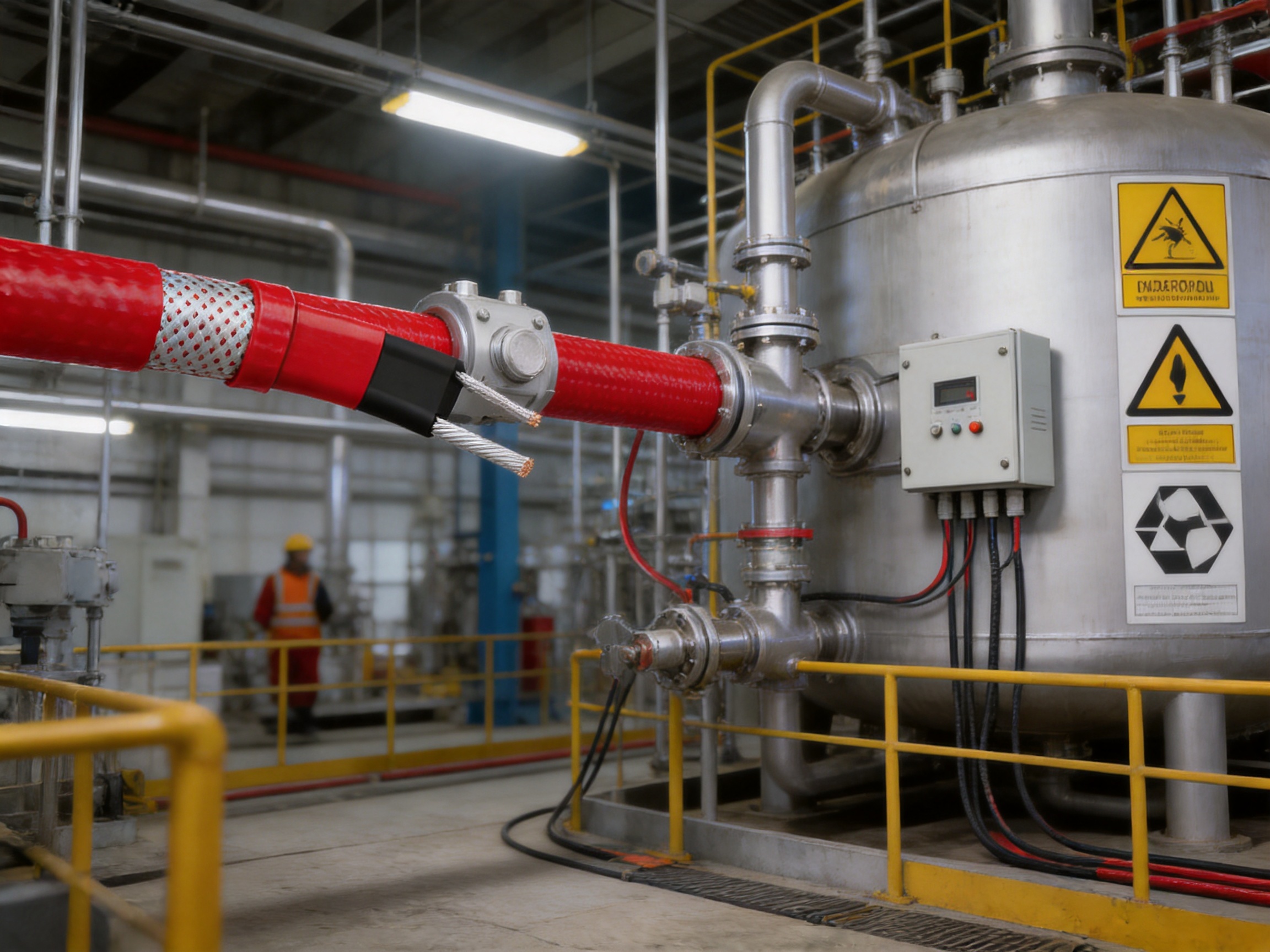
A well-designed self-regulating heat tracing system can provide long service, but periodic inspection is still required. Maintenance should include visual inspection of insulation cladding, cable termination areas, junction boxes, glands, labels, and signs of mechanical or chemical damage.
Declining insulation resistance may indicate moisture penetration, damaged insulation, a defective termination, or aging of the heating cable. If a circuit trips repeatedly, the cause should be investigated rather than bypassed. Possible causes include excessive circuit length, low-temperature startup current, damaged cable, moisture, an unsuitable breaker, or a problem with the residual-current device.
A circuit that draws less current than expected may have an open connection, a damaged bus wire, an incorrectly installed termination, or a loss of supply. A circuit that draws substantially more current than expected may have a short circuit, damaged insulation, an incorrect voltage, or a wiring error.
Temperature problems may result from inadequate insulation, missing cable at heat sinks, incorrect cable spacing, a failed controller, poor thermal contact, or an inaccurate temperature sensor. The self-regulating function should not be treated as a substitute for proper thermal insulation and layout.
Maintenance records should include the original commissioning measurements, periodic insulation-resistance results, circuit current, ambient conditions, process temperature, and any repairs. Trend monitoring can help identify deterioration before a freeze event or process interruption occurs.
Self-regulating heat tracing can support energy efficiency because the cable naturally reduces output as the surrounding temperature increases. This is particularly helpful when ambient conditions fluctuate during the day or when different areas of a pipe have different thermal conditions.
Energy performance still depends strongly on insulation quality. Poor insulation can cause continuous high output and increase operating costs. Correct insulation thickness, sealed cladding, and suitable treatment of valves and supports are essential to obtain the expected efficiency.
Control systems can further reduce energy use by switching circuits according to ambient temperature, process temperature, or operating schedules. However, controls should be selected so that they do not create unsafe conditions in hazardous areas or prevent frost protection during unexpected shutdowns.
The product’s long-term environmental performance also depends on service life, repairability, and proper disposal. Damaged cable and electrical accessories should be handled according to local waste and electrical-equipment requirements. A durable fluoropolymer jacket can reduce premature replacement where chemical exposure would otherwise cause early failure.
When purchasing UFC self-regulating heating cables, buyers should specify the exact model, voltage, required length, jacket requirements, accessories, certification, packaging, and documentation. The purchase order should identify whether the cable is intended for ordinary industrial use, hazardous-area use, steam-cleaned equipment, or process maintenance.
It is also important to purchase compatible accessories at the same time. These may include power connection kits, end seals, splice kits, tee connection kits, junction boxes, glands, mounting materials, temperature controllers, sensors, circuit protection, and warning labels.
For export projects, the buyer should confirm the standards required by the destination country. European hazardous-area requirements, North American certification systems, Eurasian requirements, and local electrical regulations may differ. Certification must be current and applicable to the exact model and accessory combination.
A technical data sheet should be reviewed for output, maximum exposure temperature, minimum installation temperature, bend radius, maximum circuit length, chemical compatibility, and temperature classification. If the source document contains ambiguous table formatting or nonstandard units, clarification should be obtained before final approval.
The primary purpose is to protect pipes and vessels from freezing and to maintain selected process temperatures. The range is particularly suited to applications involving steam cleaning and chemical exposure because it uses a fluoropolymer outer jacket and is designed for demanding industrial environments.
Yes. The supplied product information states that the cables can maintain processes up to 121°C under appropriate design conditions. The exact model, temperature classification, control method, insulation system, and exposure conditions must be checked for each project.
A fluoropolymer jacket offers high resistance to many chemicals, organic substances, moisture, and environmental contaminants. It is useful where the cable may be exposed to corrosive materials, aggressive cleaning agents, or industrial chemicals. Compatibility should still be confirmed for the exact chemical and temperature.
The supplied information identifies the range for Zone 1 and Zone 2 gas areas and Zone 21 and Zone 22 dust areas when properly certified and installed. The exact model certification, temperature classification, accessories, and installation method must be verified before use.
It means that the cable changes its heat output in response to the surrounding temperature. A colder section produces more heat, while a warmer section produces less. This local response helps accommodate changing ambient conditions and reduces the risk of overheating compared with many fixed-output systems.
No. Self-regulation reduces the need for constant temperature switching in some frost-protection applications, but a thermostat, controller, limiter, or monitoring system may still be required for process control, hazardous-area temperature limitation, energy management, or compliance with project specifications.
The supplied data lists 24 Vac, 36 Vac, 110 Vac, 230 Vac, and 400 Vac. The available voltage should be confirmed for the selected model and order configuration. It must be matched with the site supply, circuit length, protective device, and control equipment.
The reference output values at 10°C are listed as 13 W/m for 4UFC-CT, 26 W/m for 8UFC-CT, 40 W/m for 12UFC-CT, 50 W/m for 15UFC-CT, and 66 W/m for 20UFC-CT. Actual output changes with temperature and installation conditions.
Parallel-circuit self-regulating cables are generally suitable for field cutting to the required length, provided that the manufacturer’s instructions are followed and approved end seals are installed. The maximum circuit length and electrical protection limits must not be exceeded.
The supplied specification lists a minimum installation temperature of -60°C. At low temperatures, the specified bend radius becomes larger. Installers should avoid sharp bends, impact, twisting, and excessive pulling during cold-weather work.
Yes, the range is specifically intended for frost protection of pipes and vessels that require steam cleaning. The supplied data identifies a maximum intermittent exposure temperature of 215°C under a stated saturated-steam condition and a maximum cumulative exposure time of 1,000 hours. The cable should be de-energized when required, and the complete installation must be designed for the cleaning cycle.
The supplied information recommends a 30 mA leakage protection device for maximum safety and fire prevention. In applications with high normal leakage current, a device up to 300 mA may be considered after a qualified safety assessment. Circuit breakers must also be selected according to the cable type, starting temperature, circuit length, and local standards.
Important information includes pipe or vessel dimensions, required maintenance temperature, minimum ambient temperature, insulation type and thickness, pipe material, chemical exposure, steam-cleaning conditions, supply voltage, hazardous-area classification, circuit length, and the desired control method.
The manufacturer reports more than 35 years of industry experience, a portfolio covering several electric heating technologies, ISO 9001 quality system certification, national CCC certification, product development activities, an irradiation center, international market experience, and a network of distributors. Project-specific certificates and test documents should be requested for approval.
Maintenance should include visual inspection, insulation-resistance testing, continuity checks, examination of terminations and junction boxes, verification of residual-current protection, and inspection of thermal insulation and weatherproof cladding. Repeated tripping or abnormal temperature should be investigated by qualified personnel.
UFC self-regulating heat tracing cables provide a flexible solution for frost protection, process temperature maintenance, and industrial systems exposed to chemical substances and steam-cleaning conditions. Their temperature-responsive output, fluoropolymer outer jacket, broad voltage range, low-temperature installation capability, and hazardous-area suitability make them appropriate for demanding applications when correctly designed and installed.
Compared with constant-wattage cables, fixed resistance wire, steam tracing, and some high-temperature cable systems, self-regulating technology can simplify layout, accommodate temperature differences, and reduce the risk of excessive local heating. Its advantages are strongest when combined with proper insulation, approved accessories, reliable electrical protection, documented hazardous-area compliance, and an appropriate control strategy.
The manufacturer’s experience in electric heating, product development, quality management, international certification, and multiple heating technologies provides a foundation for standard and customized projects. Nevertheless, the final choice should always be based on verified technical data for the exact model, current certification, chemical compatibility, circuit calculations, exposure temperatures, and local regulations.
For engineers and plant operators, the most important principle is to treat the heating cable as one part of a complete thermal and electrical system. When cable selection, manufacturing quality, installation practice, protection, insulation, and maintenance are properly coordinated, UFC self-regulating heat tracing can provide dependable long-term protection for industrial pipework and equipment.
1. Product technical information for UFC self-regulating heat tracing cables, including application, output, dimensional, temperature, and circuit-length data.
2. EN 60079-30-1, Explosive atmospheres — Electrical resistance trace heating — General and testing requirements.
3. IEC 60898, Electrical accessories — Circuit-breakers for overcurrent protection for household and similar installations.
4. ISO 9001, Quality management systems — Requirements.
5. General engineering practices for electrical heat tracing design, insulation, circuit protection, hazardous-area installation, commissioning, and maintenance.
6. Manufacturer guidance for heating cable installation, termination, chemical compatibility, temperature limitation, and hazardous-area applications.
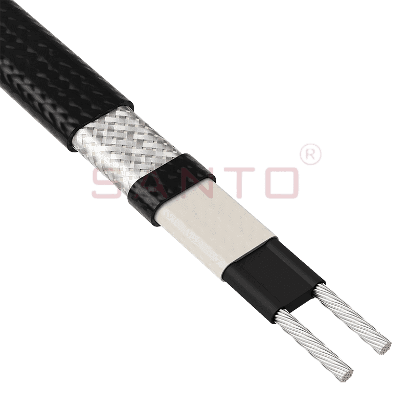
The SANTO UFA range of self-regulating heating cables is mainly used for frost protection of pipes and vessels but can also be used to maintain processes up to 65°C. These heating cables are available...
See Details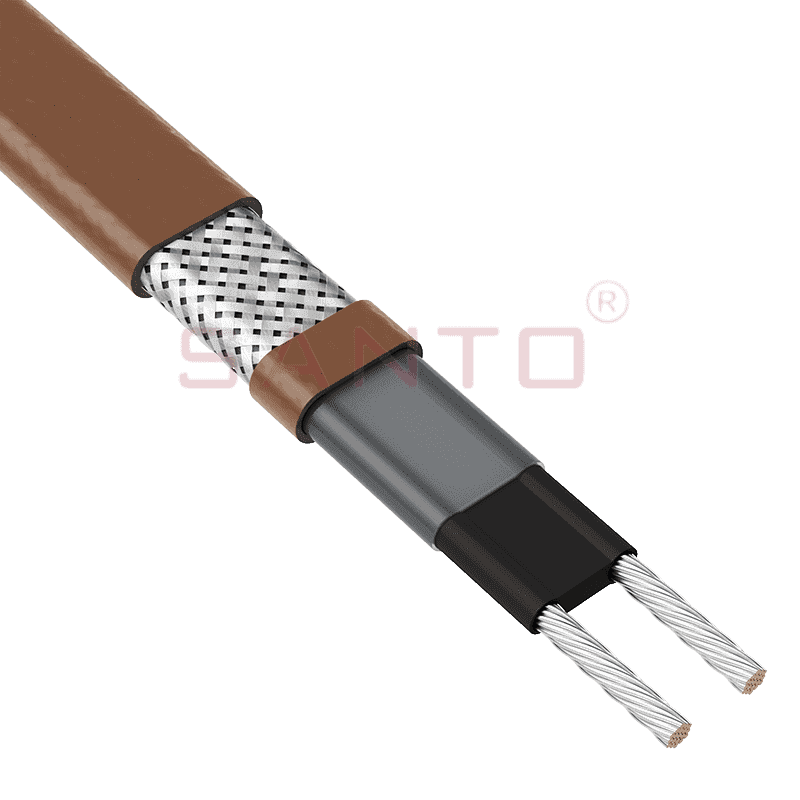
The SANTO UFB range of self-regulating heating cables is mainly used for frost protection of pipes and vessels requiring a higher power output than the UFA heating cables can supply. They can also be ...
See Details
The SANTO UFC range of self-regulating heating cables is used for frost protection of pipes and vessels that require steam cleaning. They can also be used to maintain processes up to 121°C. These heat...
See Details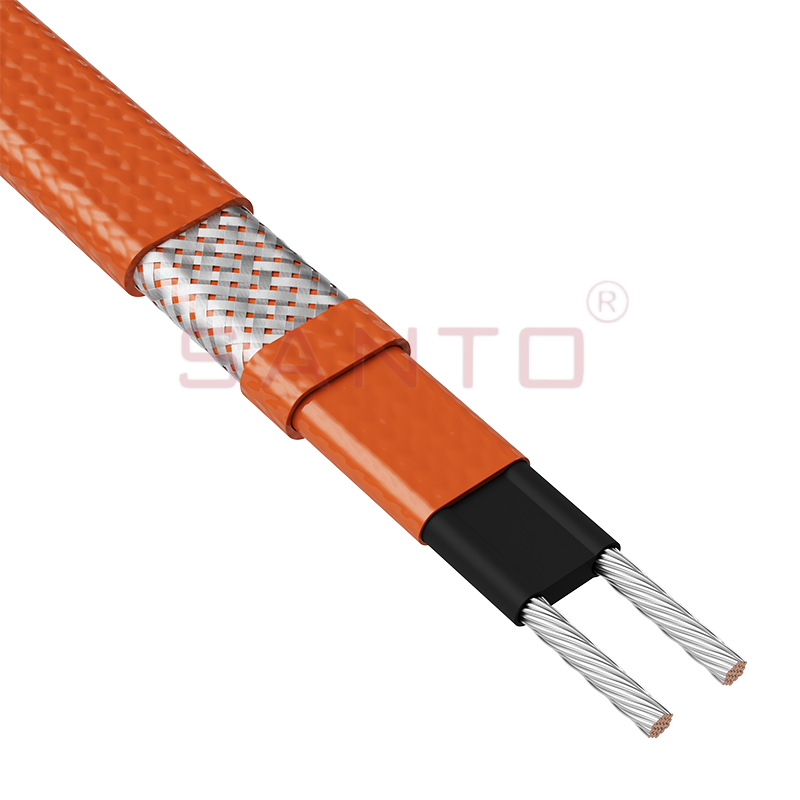
The SANTO UFO range of self-regulating heating cables is mainly used for frost protection of pipes and vessels that require steam cleaning . They can also be used to maintain processes up to 150°C. Th...
See Details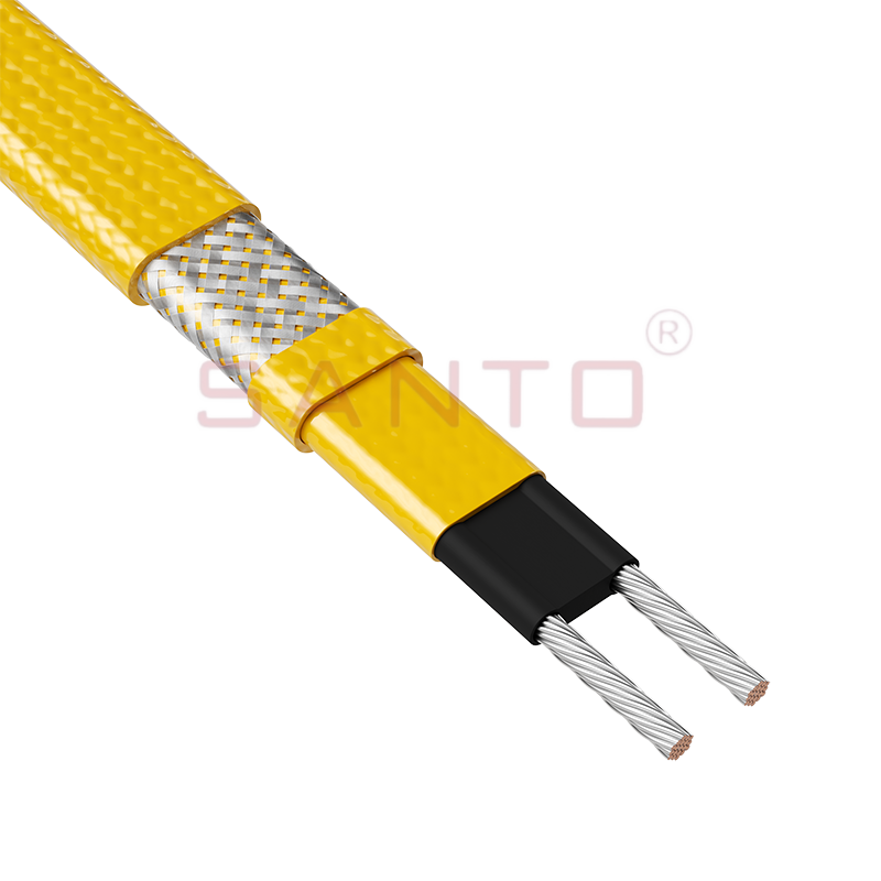
The SANTO UFD series of self-regulating heating cables are mainly used for freeze protection of pipes and vessels, but can also be used to maintain processes up to 200°C. These heating cables are avai...
See Details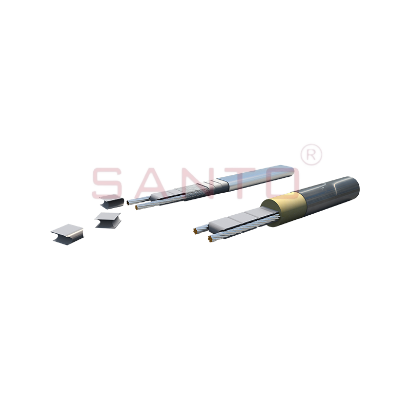
SANTO UFY heating wire is suitable for applications that maintain process temperatures up to 260 ℃ and can be steam blown; The self-regulating and parallel circuit heating wires of the UFY series are ...
See Details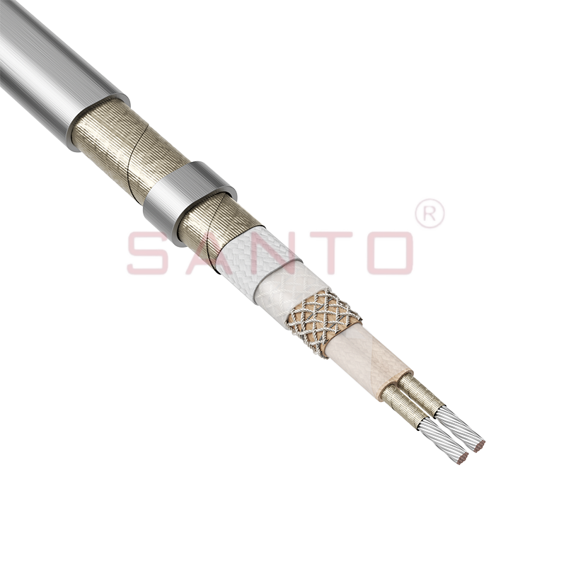
The SANTO UFM series self-regulating heating cables are mainly used for freeze protection of pipes and vessels, but can also be used to maintain processes up to 400°C. These heating cables are availab...
See Details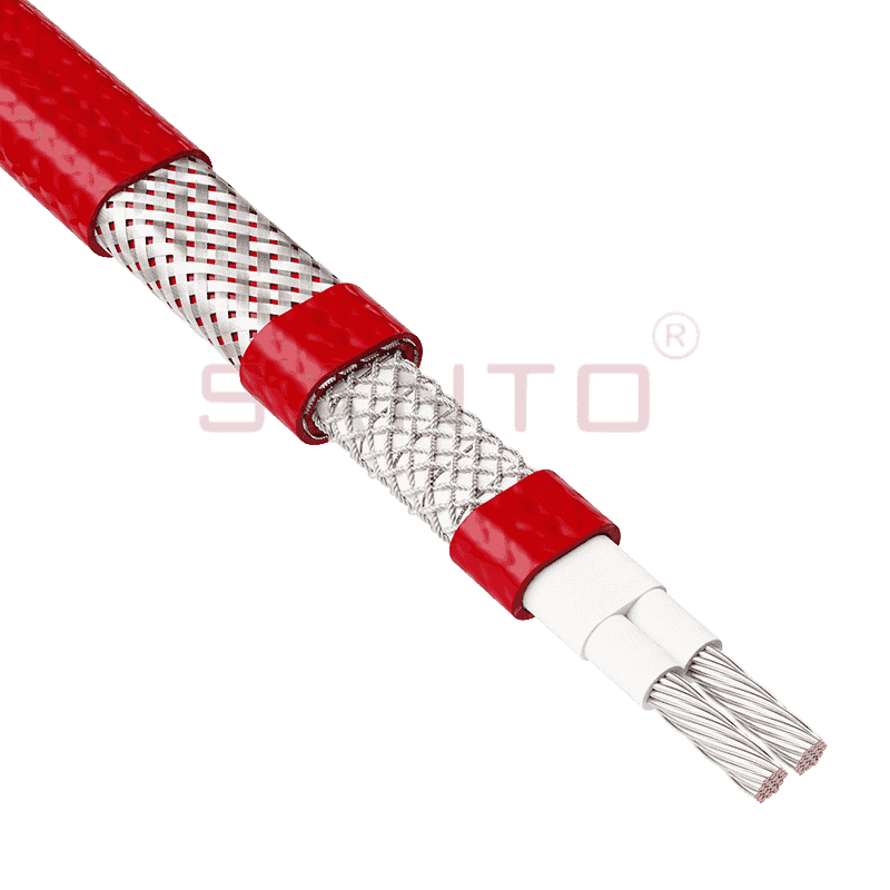
The SANTO ACC range of power-limiting heating cables is mainly used for temperature maintenance of processes and offers the advantage of a high power output at high temperatures which can reduce the n...
See Details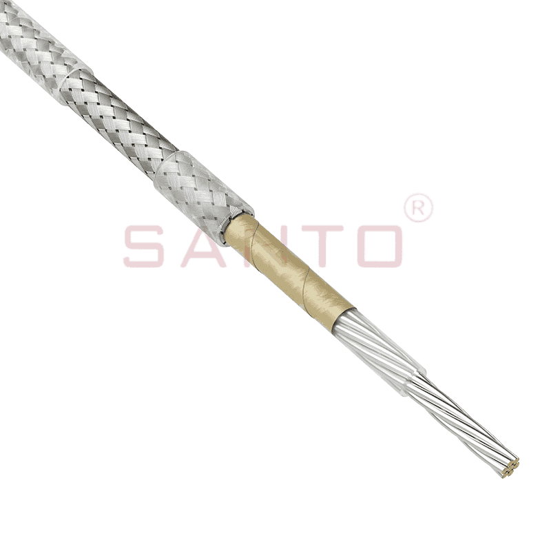
The stranded high temperature conductor is nickel plated to ensure a long life at elevated temperatures in corrosive environments. It is electrically isolated using an innovative sandwich construction...
See Details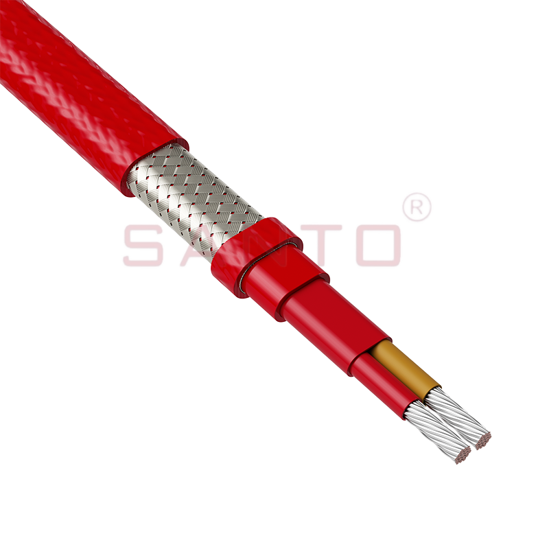
The stranded high temperature conductor is nickel plated to ensure a long life at elevated temperatures in corrosive environments. It is electrically isolated using an innovative sandwich construction...
See Details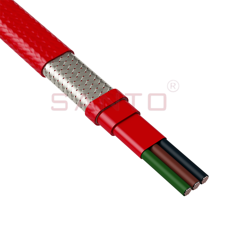
The stranded high temperature conductor is nickel plated to ensure a long life at elevated temperatures in corrosive environments. It is electrically isolated using an innovative sandwich construction...
See Details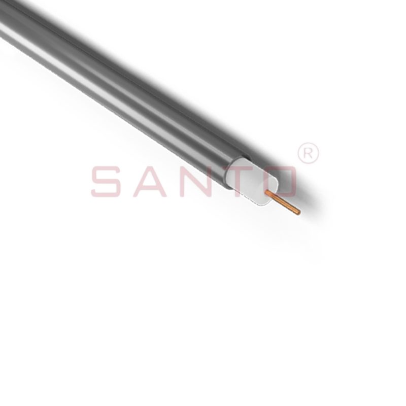
SANTO HAx mineral insulated (MI) Alloy 825 series heating cables are suitable for use in hazardous areas. They have been designed for use in freeze protection and temperature maintenance applications ...
See Details
Santo electric heating strips are widely used in key industries in China.

