 English
 English
 русский
 日本語
 Español
 中文简体

The SANTO UFA range of self-regulating heating cables is mainly used for frost protection of pipes and vessels but can also be used to maintain processes up to 65°C. These heating cables are available...
See Details
Industrial electric heating systems depend on more than the heating cable itself. A complete installation must also provide a safe, durable, and serviceable method for bringing power into the circuit, protecting the heating conductor, maintaining insulation integrity, and allowing technicians to verify operating status. The MFS-100-E and MFS-100-EP single-circuit power supply junction boxes are designed for this purpose. They connect electrical power to compatible parallel heating wires while supporting installations in demanding industrial and potentially hazardous environments.
These junction boxes are intended for use with SANTO UFA, UFB, UFC, UFO, and ABB industrial parallel heating wires, including related ACC, ADD, AFF, and XP! series companion heating products. Their design combines a protective enclosure, wiring terminals, a heating-wire core sealing sleeve, a support bracket, grounding components, and optional LED indication in one coordinated installation kit. Instead of requiring installers to source and adapt several unrelated components, the MFS-100 system provides a purpose-built interface between the power supply and the heating circuit.
The product is available in configurations for different regional installation practices. The MFS-100-A is designed for North American applications, while the MFS-100-E and MFS-100-EP versions are intended for Eurasian and similar international applications. The MFS-100-EP adds an armored-cable grounding arrangement, including a grounding plate and external grounding bolt. This makes it suitable for applications where cable armor must be incorporated into the protective earthing system.
Beyond basic electrical connection, the kit addresses several practical installation challenges. It can accommodate a 100 mm insulation layer, protect the heating wire at the entry point, and permit installation of the core sealing sleeve without a hot-air gun or spray lamp. Avoiding high-temperature tools can simplify field work, reduce ignition risks, and eliminate the need for a hot-work permit in installations where such a permit would otherwise be required.
The result is a compact and adaptable power junction solution for process piping, tanks, vessels, valves, instrumentation lines, and other equipment protected by electric heat tracing. Its value is particularly evident where reliability, hazardous-area compliance, low-maintenance construction, and installation efficiency are equally important.
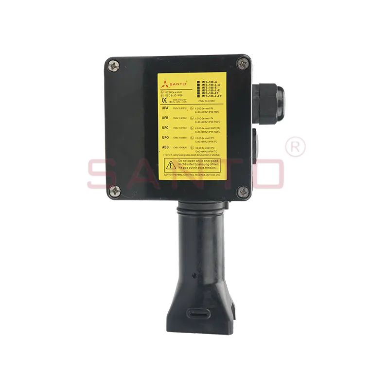
MFS-100-E/MFS-100-EP single circuit power supply junction box
Content
An electric heat-tracing circuit must transfer power from the plant distribution system to the heating cable without compromising electrical safety or environmental protection. The power junction box forms the transition point between the supply cable and the parallel heating wire. At this point, the installation needs secure terminals, suitable cable entry, grounding continuity, mechanical support, and protection against moisture, dust, and accidental contact.
The MFS-100 is engineered as a single-circuit power supply junction box. Its terminal arrangement is intended for one heating circuit and includes the necessary conductors for the relevant regional configuration. The North American version uses WAGO 284 series terminals arranged for two-wire connection and one grounding wire. The E and EP variants use a phase, neutral, and grounding arrangement suitable for their specified supply architecture.
In operation, the supply cable enters the enclosure through the designated entry arrangement. The incoming conductors are connected to the terminal blocks, while the heating-wire conductors pass through the core sealing sleeve and continue toward the companion heating circuit. The enclosure protects the connections from the surrounding environment, and the bracket provides a stable mounting point on or near the heated pipe or equipment.
A correctly designed junction box must manage both electrical and thermal conditions. Heat tracing can expose components to elevated process temperatures, while outdoor or cold-climate installations can expose them to freezing conditions. The MFS-100 specifications identify a general ambient and installation temperature range down to minus 50 degrees Celsius for the listed configurations. The maximum pipeline temperature is determined by the specifications of the companion heating wire, which is an important engineering distinction: the junction box does not independently define the allowable process temperature of the complete heat-tracing system.
The enclosure is also intended to support installations beneath thermal insulation. The 100 mm insulation-layer capability helps installers maintain a continuous insulation system around the traced pipe or equipment. A suitable support arrangement reduces pressure on the heating wire and helps keep the connection point correctly positioned during insulation work.
The MFS-100 family is not limited to a single connection format. Three basic configurations are provided so that the installer can select the appropriate cable entry, grounding arrangement, and regional hardware. The configurations share a common purpose and general enclosure concept, but each addresses a different field requirement.
| Configuration | Typical regional application | Entry arrangement | Grounding arrangement | Protection rating | Maximum working voltage | Maximum heating-circuit current |
|---|---|---|---|---|---|---|
| MFS-100-A / MFS-100-L-A | North American applications | One 3/4-inch through hole | Grounding wire arrangement | NEMA 4X | 277 Vac | 50 A |
| MFS-100-E / MFS-100-L-E | Eurasian and international applications | Two M25 threaded entries; one gland and one plug supplied | Terminal-based protective grounding | IP66/IP67 | 254 Vac | 40 A |
| MFS-100-EP / MFS-100-L-EP | Applications using armored cables | Two M25 entries | Internal grounding plate and external grounding bolt | IP66/IP67 | 254 Vac | 40 A |
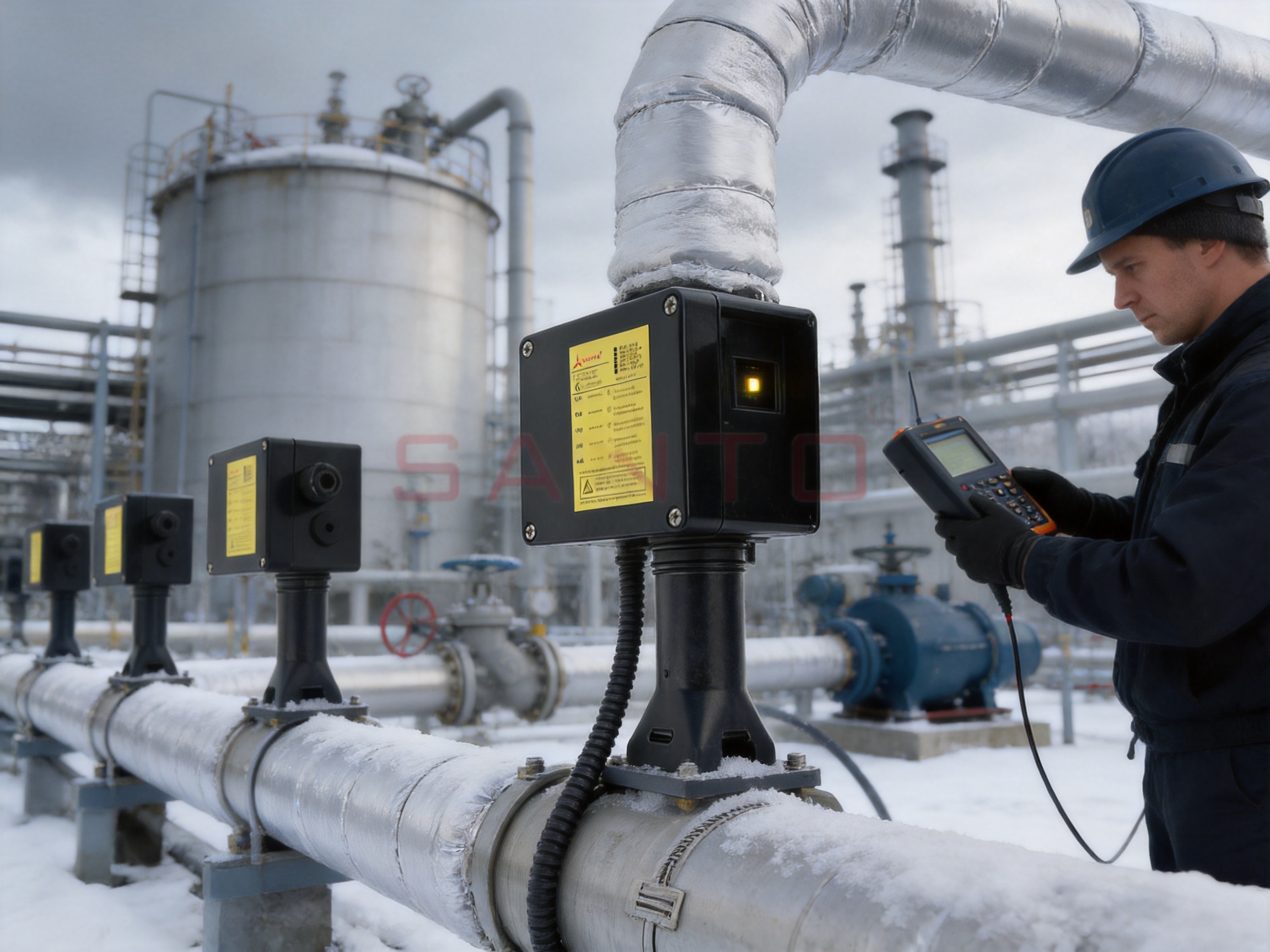
The product information uses suffixes such as “-L” to identify versions equipped with an indicator module. The indicator option provides a visual signal through an ultra-bright LED positioned behind a viewing area in the cover. This allows personnel to determine whether the junction box is energized without opening the enclosure, provided the installation and indicator circuit have been correctly configured.
The MFS-100-A is supplied with a through-hole arrangement intended to work with a 3/4-inch sleeve. It is rated NEMA 4X and supports a maximum heating-wire circuit current of 50 amperes, with a maximum working voltage of 277 Vac. This configuration is appropriate where North American connection practices and enclosure classifications are required.
The MFS-100-E includes two M25 threaded holes, an M25 power-cable gland for cable diameters from 8 to 17 mm, and an M25 plug. This arrangement allows one entry to be used for the incoming power cable while the unused opening is closed with the supplied plug. The E version is rated IP66/IP67 and supports up to 40 amperes at a maximum working voltage of 254 Vac.
The MFS-100-EP is designed for armored-cable installations. In addition to its M25 entries, it includes a galvanized and blue-chrome-plated steel grounding plate and an external grounding bolt. These features support a more controlled bonding arrangement between the cable armor and the protective earthing system. For industrial plants where armored cable is selected for mechanical protection or installation standards, this configuration can be more suitable than a basic gland-and-terminal arrangement.
Heat-tracing junction boxes are often installed outdoors, in utility areas, on process skids, or near equipment exposed to washdown, condensation, dust, and temperature cycling. A junction box that performs well only in a dry indoor environment may create a weak point in an otherwise robust heat-tracing system. The MFS-100 enclosure uses engineering polymer for the shell, lid, and bracket, with stainless-steel cover screws and a silicone-rubber cover gasket.
The engineering-polymer construction provides a combination of low weight, electrical insulation, and resistance to many industrial environmental conditions. A lighter enclosure can be easier for one technician to position during installation, while the nonmetallic body helps avoid unnecessary corrosion concerns associated with some exposed metal housings. The black finish is also practical for industrial service and visually integrates with many insulated or coated piping systems.
Stainless-steel cover screws are used to improve resistance to corrosion at the enclosure fastening points. The silicone-rubber gasket helps maintain the environmental seal between the lid and the enclosure body. Together, the gasket and fastener arrangement support the stated NEMA 4X or IP66/IP67 protection levels, when the product is correctly installed and all cable entries, plugs, and accessories are properly fitted.
NEMA 4X is commonly associated with protection against windblown dust and rain, splashing water, hose-directed water, and corrosion, together with protection against accidental contact with internal components. IP66 indicates protection against dust ingress and powerful water jets, while IP67 indicates protection against temporary immersion under defined test conditions. These ratings describe enclosure protection under specified conditions; they do not remove the need for correct installation, compatible glands, proper cover closure, and periodic inspection.
In real applications, environmental protection depends on the entire assembly. A high-quality enclosure can still leak if the gland is incorrectly tightened, if the plug is not properly seated, if the gasket is damaged, or if cables are bent in a way that places continuous stress on the entry point. The MFS-100 kit approach helps reduce this risk by supplying coordinated components for the relevant configuration.
The MFS-100 kit is described as certified for hazardous-area use through CNEX, IECEx, ATEX, DNV, Baseefa, and EAC-related approvals. The applicable certification depends on the exact product version, installation region, heating cable, ambient temperature, and system arrangement. Therefore, project engineers should always verify the current certificate and installation conditions before specifying the product for a particular hazardous location.
Hazardous-area installations require careful control of ignition sources. Electrical terminals must be correctly rated, cable entries must maintain the required protection concept, unused openings must be sealed, and the enclosure must not be modified in a way that invalidates certification. The MFS-100 design supports these requirements through purpose-selected terminals, enclosure materials, cable entry components, and grounding provisions.
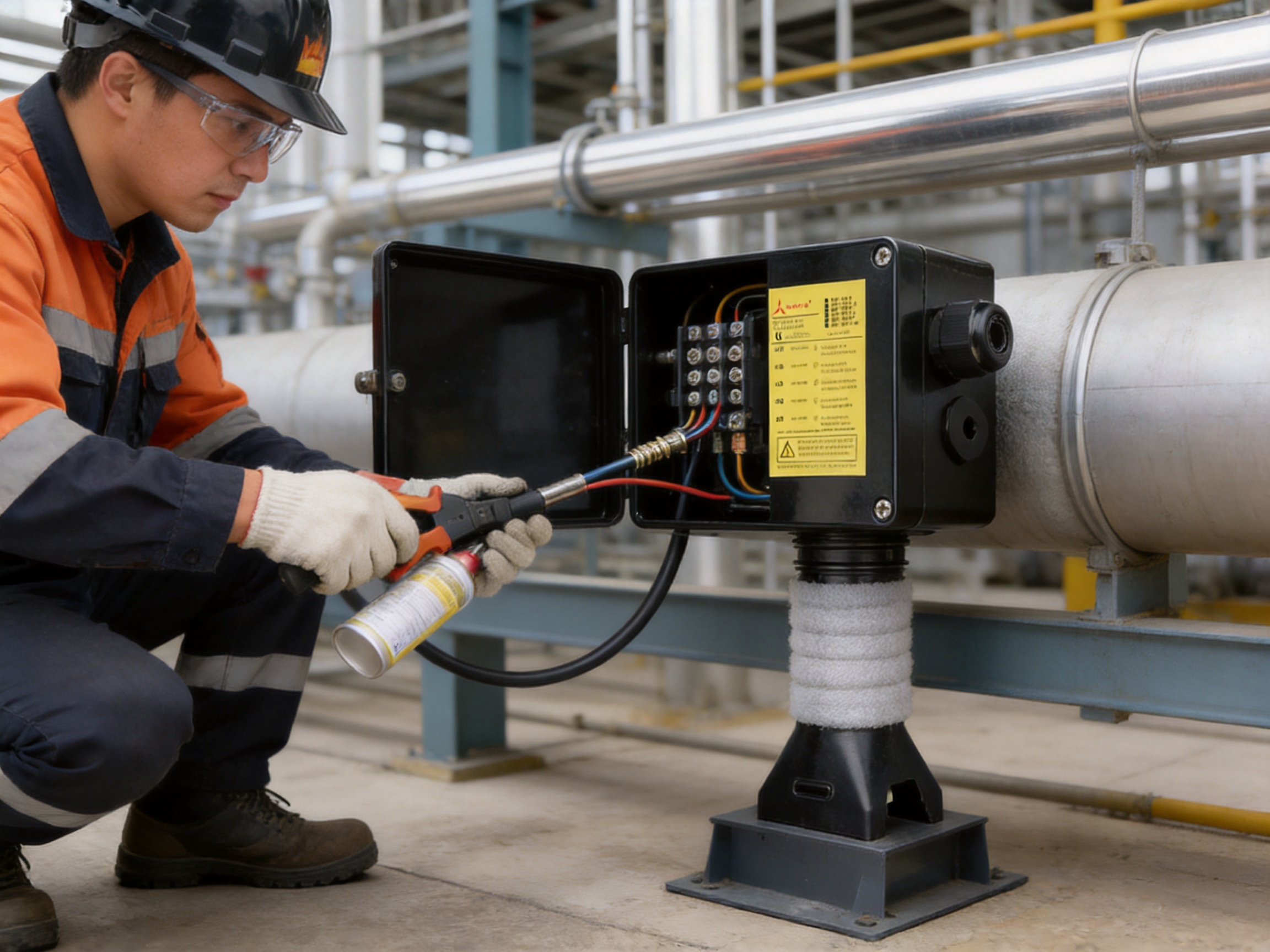
One notable installation advantage is the core sealing sleeve. The sleeve can be installed without a hot-air gun or spray lamp. This cold-installation approach can simplify work in operating facilities, especially where open flame, hot surfaces, or temporary heating tools are restricted. It can also reduce the number of tools required by the installer and help avoid delays associated with obtaining a high-temperature work permit.
Eliminating hot work does not eliminate the need for safe electrical work. The circuit must be isolated, locked out, and verified de-energized before connections are made. Technicians should use approved tools, follow the applicable hazardous-area procedures, maintain conductor identification, and confirm that the cable gland, sleeve, bracket, and enclosure are installed according to the product instructions.
The MFS-100-EP version adds a specific advantage where armored cable is used. The grounding plate and external grounding bolt provide a defined point for bonding the armor. Proper armor bonding can help maintain equipotential continuity and improve fault-current paths, subject to the applicable electrical code and project grounding design.
Certification is not a substitute for system engineering. The heating wire, power supply, overcurrent protection, ambient temperature, process temperature, insulation system, and junction box must be considered together. A technically correct junction box can only perform as intended when the complete circuit is designed and installed within its certified parameters.
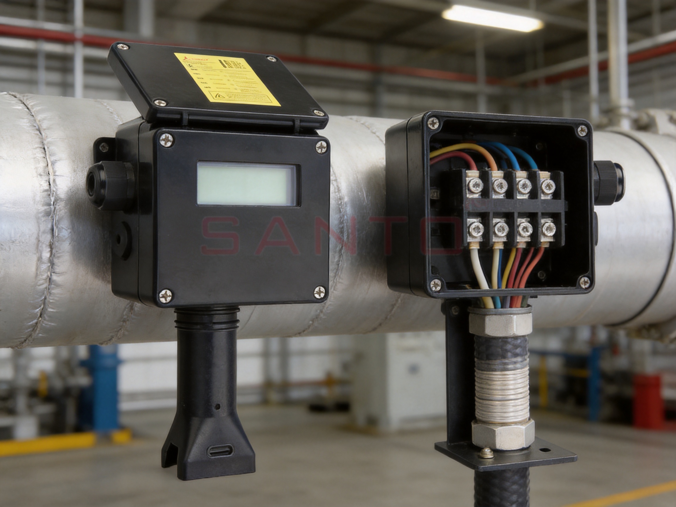
The terminal blocks are based on the WAGO 284 series for the listed configurations. The specified terminal arrangement is intended to provide a secure connection for the incoming supply and heating conductors while maintaining the necessary separation and grounding path. The exact conductor preparation, tightening method, and allowable conductor type should follow the approved installation instructions for the selected model.
The North American configuration supports up to 8 AWG stranded wire and a maximum working voltage of 277 Vac. Its maximum continuous working current is listed as a 50-ampere heating-wire circuit. The E and EP configurations support up to 10 square millimeters for multi-strand conductors and 10 square millimeters for solid electrical building wire, with a maximum working voltage of 254 Vac and a maximum heating-circuit current of 40 amperes.
These values are important for circuit selection and should not be treated as universal design targets. The actual operating current must be established from the heating cable load, circuit length, supply voltage, ambient conditions, and required design margin. Overcurrent protection should be selected in accordance with the heating cable data and the applicable electrical regulations. The junction box should never be used to justify a circuit current that exceeds the heating cable, terminal, cable gland, or protective-device rating.
The one-circuit arrangement is useful for installations where each traced line or equipment section must be separately controlled, monitored, or isolated. Individual circuit connection can simplify troubleshooting because a technician can identify the power path associated with a particular pipe run. It can also support independent temperature-control zones and reduce the consequences of a fault in one branch.
For larger systems, multiple MFS-100 units may be installed as part of a coordinated heat-tracing design. The number of circuits, enclosure locations, control panels, and monitoring points should be determined from a heat-loss calculation and a detailed electrical schedule. Junction boxes should remain accessible for inspection and should not be permanently buried beneath insulation or obstructed by other plant components.
The optional luminous module is one of the practical features of the MFS-100 family. The module contains an ultra-bright LED and is designed to be inserted into the wiring terminal. A viewing area in the cover allows the status of the junction box to be observed from outside the enclosure.
The indicator can provide a quick visual check of energization during routine rounds. This is especially useful when junction boxes are installed on elevated pipe racks, behind protective guards, or in areas where opening the enclosure would be inconvenient. A visible red or green signal can help maintenance personnel determine whether the circuit may be live before beginning a more detailed test procedure.
The indicator colors listed for the configurations are red for the North American version and green for the E and EP versions. The optional module is associated with the “-L” variants. The voltage rating is 100 to 277 Vac for the A version and 100 to 254 Vac for the E and EP versions. Power consumption is listed as less than one watt.
Visual indication should be treated as a supplementary diagnostic feature rather than the sole proof of isolation. An LED can fail, may be difficult to see in bright sunlight, or may indicate the presence of voltage at one point without proving that every conductor is safe. Before maintenance, authorized personnel should always use an approved test instrument and follow the site isolation procedure.
Compared with a junction box that offers no external indication, the optional LED can reduce unnecessary cover removal. Fewer enclosure openings can help preserve gasket life and reduce the chance of introducing dust or moisture during routine checks. It can also support preventive maintenance by making abnormal status easier to notice during scheduled inspections.
Thermal insulation is essential to the efficiency of an electric heat-tracing system. Without adequate insulation, heat losses increase, electrical consumption rises, and the heating cable may struggle to maintain the target temperature. The MFS-100 kit includes a bracket designed to support the connection assembly and accommodate a 100 mm insulation layer.
The bracket performs several functions. It helps keep the junction box positioned relative to the pipe or equipment, reduces mechanical stress on the heating-wire entry point, and provides a repeatable mounting arrangement for installers. It also helps protect the heating wire where it transitions into the enclosure. A supported connection is less likely to be pulled, bent sharply, or displaced during insulation installation.
Insulation should be installed without crushing the junction box, cable entries, or heating cable. The insulation cladding should be arranged so that the junction box remains identifiable and accessible. Where removable insulation jackets are used, the junction box can be inspected without dismantling a large section of permanent insulation.
The provision for a 100 mm insulation layer is particularly valuable in industrial applications requiring substantial thermal resistance. Such applications may include process piping, tanks, pumps, valves, loading lines, and freeze-protection systems. The correct insulation thickness remains a project design decision based on process temperature, ambient conditions, wind exposure, pipe size, and the heat-tracing objective.
The junction box itself is not a replacement for proper insulation design. It is an interface component that helps the heat-tracing system maintain a mechanically and thermally organized installation. When combined with correctly selected insulation and a compatible heating cable, it contributes to a more stable and maintainable system.
Traditional termination methods for some heating cables may require heating tools to shrink or cure sealing components. In areas with flammable materials, volatile chemicals, or strict permit systems, hot-air guns and open-flame tools can complicate work planning. The MFS-100 core sealing sleeve is designed to avoid this requirement.
The cold-installation method offers several operational benefits. First, it reduces the possibility of accidental ignition caused by an open flame or uncontrolled hot surface. Second, it can shorten preparation time because the installer does not need to arrange a spray lamp, hot-air gun, or associated permit. Third, it makes the installation more practical in cold weather or confined locations where heating tools are difficult to use.
It also supports consistency between factory-prepared and field-installed connections. The installer can focus on correct conductor preparation, sleeve positioning, lubrication where specified, and mechanical assembly rather than attempting to apply heat evenly around a sealing component. This can improve repeatability, provided the instructions are followed accurately.
The kit includes lubricant for the sealing process. Lubrication should be used only as specified by the manufacturer, because an incompatible substance could affect the sealing material, compromise mechanical retention, or create contamination inside the enclosure. The supplied cable tie also helps organize conductors and maintain a clean internal layout.
A cold-installation seal still requires inspection. The sleeve should be checked for correct seating, visible damage, contamination, and appropriate compression or engagement. The surrounding cable should not be under excessive tension. The final assembly should be evaluated for both electrical integrity and environmental sealing before the circuit is energized.
The product is manufactured by Santo Thermal Control Technology Co., Ltd., a specialist company focused on electric heating and thermal-control products. The company’s stated product range includes automatic temperature-control heating belts, self-limiting heating belts, heat-tracing cables, constant-power heating cables, glass-fiber heating products, silicone-rubber heating products, mineral-insulated cables, snow-melting cables, LCD-tracked heaters, and related accessories.
This product breadth is relevant to the MFS-100 because a junction box for heat tracing must be compatible with the electrical, thermal, and mechanical characteristics of the heating cable. A general-purpose electrical enclosure manufacturer may produce a strong box, but a specialist heat-tracing manufacturer can develop the connection kit around the needs of heating-wire terminations, insulation interfaces, cable-core seals, and process-temperature applications.
The company reports more than 35 years of industry experience, annual output exceeding 10,000 units or products across its operations, more than 2,000 distributors, and business coverage in over 85 regions. These figures indicate a manufacturing and distribution structure capable of supporting both standard products and export-oriented configurations. They also suggest experience with differing regional electrical practices and certification expectations.
The stated development history includes the founding of an electric heating instrument factory in 2000, ISO9001 quality-system certification in 2002, the establishment of an irradiation center in 2013, and the creation of the SANTO brand in 2016. The company also reports explosion-proof and EAC certification activities, product development in carbon-fiber parallel heating cable technology, factory expansion, and the establishment of a Russia-based factory.
A further strength is the company’s stated integration of research, design, production, manufacturing, and sales. Vertical coordination can improve product development because feedback from installation projects can be returned to the engineering and production teams. For a kit such as the MFS-100, small details—including the geometry of the bracket, the fit of the sealing sleeve, terminal organization, and cover visibility—can have a major impact on field performance.
The company also reports cooperation in product research with Harvard University, participation in technology-development programs, and recognition as a high-tech enterprise in Jiangsu Province. Such claims should be evaluated through appropriate documentation during supplier qualification, but they demonstrate an emphasis on technical development rather than simple commodity assembly.
A reliable power junction box begins with controlled materials. The enclosure polymer must maintain mechanical strength, dimensional stability, and environmental performance across the specified temperature range. The gasket must retain elasticity and sealing capability. Stainless-steel screws must be compatible with the enclosure and resist corrosion. Terminals, glands, plugs, grounding plates, and sleeves must match the approved product configuration.
Manufacturing control should include incoming-material inspection, dimensional verification, assembly checks, electrical continuity testing, and visual inspection. For an enclosure supplied for hazardous-area applications, traceability and configuration control are especially important. A product certificate applies to a defined assembly. Substituting an unapproved gland, changing the enclosure opening, or using a non-compatible sleeve can affect the certified protection concept.
The MFS-100 kit format supports assembly consistency by grouping the principal components required for the selected installation. The standard kit compositions include the junction box, wiring terminals or terminal blocks, bracket, core sealing sleeve, yellow-and-green grounding-wire sleeve, lubricant, and cable tie. The E version adds an M25 power-cable gland and plug, while the EP version includes the grounding plate, external grounding bolt, and M25 plug.
Component grouping can reduce procurement errors. When installers receive all relevant parts in one kit, there is less dependence on unverified substitutions from different suppliers. It can also simplify warehouse management and reduce the chance that a small but essential part, such as an enclosure plug or grounding sleeve, will be missing at the time of installation.
The manufacturing process should also account for the relationship between the enclosure, terminal, and heating wire. The heating wire must enter without excessive bending, the terminals must remain accessible, and the cover must close without pinching conductors. Correct internal layout is not merely cosmetic; it affects creepage, clearance, mechanical strain, heat dissipation, and long-term serviceability.
Quality management is supported by the company’s stated ISO9001 quality-system certification and its product certification experience. For industrial buyers, further supplier evaluation may include review of current certificates, test reports, batch records, material declarations, inspection procedures, and after-sales support. These documents help confirm that production remains consistent with the technical data presented for the product.
A generic junction box may provide an enclosure and terminal block, but it does not necessarily solve the complete connection problem associated with electric heat tracing. The MFS-100 has several advantages because its design is centered on a specific heating-cable application.
The first advantage is system compatibility. The kit is intended for named parallel heating-wire families and related industrial heating products. This reduces the need for installers to improvise a transition between the cable and the power supply. Compatibility still must be confirmed for each project, but the product is developed as part of a heating-system range rather than as an unrelated electrical enclosure.
The second advantage is integrated sealing. The supplied core sealing sleeve is designed for the heating-wire entry and can be installed without high-temperature tools. A generic enclosure may require an additional termination method that is slower, more difficult to certify, or less appropriate for hazardous-area work.
The third advantage is the insulation-layer bracket. Generic boxes are often mounted directly to a support or placed awkwardly beneath the insulation system. The MFS-100 bracket is designed to protect the heating wire and support a 100 mm insulation layer, helping maintain a more orderly installation.
The fourth advantage is regional flexibility. The A, E, and EP versions address different entry and grounding needs. This avoids forcing every project into one cable-entry format. The armored-cable version is particularly useful for plants that specify armored supply cables for mechanical protection or electrical installation practice.
The fifth advantage is external visual indication. The optional LED module makes it possible to identify an energized junction box through the cover. A generic box without this feature may require cover removal or instrument testing for every basic status check.
The sixth advantage is hazardous-area orientation. The MFS-100 is presented with multiple hazardous-area certifications and protection ratings. A standard indoor junction box would not normally offer the same basis for use in classified locations. Certification must still be verified for the exact variant, but the product’s intended market and design provide a stronger starting point for hazardous industrial applications.
Finally, the kit reduces the number of separate components that must be selected and assembled. This can improve installation efficiency, simplify training, and reduce the risk of incompatible materials being combined in the field.
The MFS-100 can be used wherever a compatible electric heating cable requires a protected single-circuit power connection. Typical applications include freeze protection of water lines, process-temperature maintenance, viscosity control, condensate prevention, roof and gutter protection, valve protection, and frost prevention for exposed equipment.
In petroleum and chemical facilities, heat tracing is commonly applied to process pipes, sample lines, instrument tubing, pumps, valves, and transfer lines. The junction box must withstand outdoor conditions and support the hazardous-area requirements of the plant. The E and EP configurations can be selected according to the regional electrical system and the type of incoming cable.
In gas-processing and utility installations, small-diameter instrument lines can be vulnerable to freezing or condensation. The product information identifies a small-tube adapter option suitable for certain pipeline sizes, including S1 or DN 25 applications, with an adapter pack designated E90515-000. Such accessories should be selected only when they match the cable and installation design.
In building and infrastructure projects, the junction box may be used with heating cables for exposed water services, ramps, loading areas, roof drainage, or other freeze-protection requirements. In these applications, the NEMA 4X version can be useful where North American enclosure practices are specified.
In cold-climate facilities, the low minimum installation temperature of minus 50 degrees Celsius provides an important design reference. The enclosure and sealing components must nevertheless be installed according to their approved conditions. The temperature of the process pipe, the ambient temperature around the enclosure, and the cable’s own temperature rating must all be considered separately.
For tanks and vessels, multiple single-circuit junction boxes may be positioned around the surface to distribute heating zones. This arrangement can support more accurate control and simplify fault localization. Mechanical supports should be arranged so that the enclosure does not interfere with access platforms, insulation cladding, drains, vents, or instrument connections.
Installation should begin with a review of the approved drawings, the heat-tracing schedule, the cable type, the supply voltage, the circuit current, and the hazardous-area classification. The selected junction-box configuration must match the regional requirements, cable-entry method, grounding design, and applicable certification.
The mounting position should be accessible, mechanically stable, and protected from unnecessary impact. The bracket should be attached in a way that supports the enclosure without damaging the pipe, insulation support, heating cable, or protective coating. The connection point should be located where the insulation can be installed continuously while the junction box remains serviceable.
Before making electrical connections, isolate the power source and verify that the circuit is de-energized. Inspect the enclosure, gasket, terminal blocks, sealing sleeve, glands, plugs, bracket, and grounding components. Do not install damaged or contaminated components.
Prepare the power cable and heating cable according to the approved instructions. Avoid sharp bends, excessive stripping, conductor nicking, or unnecessary removal of insulation. The core sealing sleeve should be positioned correctly and installed using the supplied lubricant where required. Because the sleeve does not require a hot-air gun or spray lamp, the work can be performed without high-temperature equipment, but the installer must still achieve the specified mechanical seal.
Connect conductors to the correct terminals and maintain the required phase, neutral, and protective-ground identification. For the armored-cable version, bond the cable armor to the grounding plate and external grounding bolt in accordance with the installation instructions and site grounding design. The grounding path should be tested for continuity after assembly.
Arrange the conductors so that they are not pressed against the cover, gasket, or sealing components. Install the LED module when the selected model includes the indicator option. Confirm that the viewing area is clean and that the indicator can be seen from the intended inspection position.
Install the cable gland and plug correctly. The gland must suit the actual cable diameter and be tightened according to its instructions. Any unused entry must remain sealed with the approved plug. Do not drill additional holes or substitute components without authorization from the responsible engineering and certification authorities.
Close the cover evenly and confirm that the gasket is properly seated. Perform visual inspection, conductor-continuity checks, protective-earth continuity checks, insulation-resistance tests, and any required hazardous-area inspection before energization. Test the heating circuit under controlled conditions and verify that the LED, where fitted, operates as intended.
Routine maintenance should include inspection of the enclosure, cover screws, gasket, cable entries, bracket, and surrounding insulation. Look for cracks, impact damage, corrosion of metallic accessories, loose glands, displaced insulation, water accumulation, and signs of overheating. Any damage should be assessed before the circuit is returned to service.
The LED indicator can assist with routine status checks, but it should not replace scheduled electrical testing. A circuit may remain electrically connected while the heating cable itself has developed a fault. Periodic insulation-resistance testing and functional verification are therefore important parts of a complete maintenance program.
In cold climates, condensation can accumulate inside an enclosure if temperature cycling and moisture ingress are not controlled. The listed accessory MFDRAIN-PLUG-3/4IN is intended to help prevent condensation from accumulating in the junction box and is identified as applicable to the MFS-100-L-A configuration. Drainage accessories should be selected and installed only where permitted by the enclosure design and certification requirements.
Cover gaskets are wear components. They may lose elasticity after prolonged exposure to heat, chemicals, ultraviolet radiation, or repeated opening. During maintenance, the gasket should be checked for cuts, compression set, hardening, or contamination. Stainless-steel cover screws should remain properly engaged without being over-tightened to the point of damaging the polymer enclosure.
Maintenance personnel should keep the junction-box cover and viewing area clean. Dirt or paint overspray can obscure the LED signal. The enclosure should not be painted, drilled, or modified in a way that affects heat dissipation, certification, gasket seating, or the integrity of the housing.
When insulation is removed for inspection, it should be reinstalled carefully. Damaged insulation cladding can expose the heating cable and junction box to water, impact, or ultraviolet radiation. The connection should remain supported and should not be used as a lifting point or convenient anchor for unrelated cables.
Large industrial projects often face pressure to reduce installation time without sacrificing quality. A preconfigured junction-box kit can assist by standardizing the connection method across multiple circuits. Installers can work from a common procedure while selecting the correct A, E, or EP configuration for each location.
The kit composition also supports more predictable procurement. The standard components are supplied together, reducing the number of individual purchase orders and lowering the probability of incompatible glands, plugs, sealing parts, or grounding accessories being delivered to the site.
For engineering teams, the availability of multiple configurations simplifies equipment schedules. The designer can specify a North American through-hole version, an M25 gland-and-plug version, or an armored-cable grounding version according to project needs. The electrical ratings and environmental ratings are clearly separated by configuration, helping prevent accidental mixing of specifications.
For construction teams, the cold-installation sealing method can reduce permit dependencies. In a hazardous or congested plant, avoiding a hot-air gun or spray lamp can make it easier to schedule work near operating equipment. It can also reduce the need to transport and control additional tools.
For maintenance teams, the optional LED indicator provides a useful first-level status signal, while the accessible and supported enclosure helps make inspection more practical. These features do not replace formal testing, but they can improve day-to-day awareness and reduce unnecessary intervention.
For owners, the combination of a specialist manufacturer, coordinated product family, certification experience, and standardized installation kit can reduce lifecycle uncertainty. The owner should still require correct documentation, trained installation, inspection records, and replacement parts that preserve the original approved configuration.
Selection should begin with the heating cable. Confirm that the MFS-100 is approved for the exact companion heating wire, including the cable family, conductor arrangement, maximum sheath temperature, rated voltage, and maximum circuit current. The junction box must not be selected solely from its enclosure rating.
Next, confirm the regional installation standard. Choose the A version where the project requires the North American 3/4-inch entry format and NEMA 4X classification. Choose the E version where two M25 entries, an M25 gland, an M25 plug, and IP66/IP67 protection are appropriate. Choose the EP version where armored cable requires the specified grounding plate and external bonding bolt.
Check the incoming cable diameter before ordering the E configuration. The supplied M25 gland is listed for power cables with diameters from 8 to 17 mm. If the actual cable falls outside this range, the project team must verify whether another approved gland is available for the exact certified assembly.
Confirm the circuit current and voltage. The A version is listed at up to 277 Vac and 50 amperes, while the E and EP versions are listed at up to 254 Vac and 40 amperes. The heating cable, overcurrent protection, supply cable, terminals, and control equipment must all be rated for the selected operating point.
Review the ambient and process temperatures. The general minimum installation temperature is listed as minus 50 degrees Celsius. The E and EP data distinguish between standard and indicator versions in certain temperature entries, so the exact model suffix should be checked. The maximum pipeline temperature must be taken from the companion heating-wire specification.
Determine whether an indicator module is needed. If visual energization status is valuable for inspection, select the appropriate “-L” version. If the junction box is located where visual indication is not useful, the non-indicator version may be adequate. In either case, a formal electrical testing procedure remains necessary.
Finally, confirm accessories. The drainage plug may be considered for the relevant North American indicator version where condensation control is required. The small-tube adapter can be considered for suitable DN 25 or related small-pipe applications. Accessories should always be checked for model compatibility before installation.
| Item | MFS-100-A | MFS-100-E | MFS-100-EP |
|---|---|---|---|
| Primary connection purpose | Power connection for one compatible parallel heating circuit | Power connection for one compatible parallel heating circuit | Power connection for one compatible parallel heating circuit with armored-cable grounding |
| Enclosure material | Black engineering polymer | Black engineering polymer | Black engineering polymer |
| Cover fasteners | Stainless steel | Stainless steel | Stainless steel |
| Cover gasket | Silicone rubber | Silicone rubber | Silicone rubber |
| Entry | One 3/4-inch entry | Two M25 entries; gland and plug included | Two M25 entries; plug included |
| Environmental rating | NEMA 4X | IP66/IP67 | IP66/IP67 |
| Maximum working voltage | 277 Vac | 254 Vac | 254 Vac |
| Maximum heating-circuit current | 50 A | 40 A | 40 A |
| Maximum conductor size | 8 AWG stranded | 10 mm² stranded or solid, as specified | 10 mm² stranded or solid, as specified |
| Indicator option | Red LED, 100–277 Vac, less than 1 W | Green LED, 100–254 Vac, less than 1 W | Green LED, 100–254 Vac, less than 1 W |
| Armored-cable grounding plate | Not applicable | Not applicable | Galvanized and blue-chrome-plated steel |
It connects electrical power to one compatible parallel heating-wire circuit while providing enclosure protection, terminal connection, grounding, mechanical support, and heating-wire core sealing.
The product is designed for SANTO UFA, UFB, UFC, UFO, and ABB industrial parallel heating wires, including the related ACC, ADD, AFF, and XP! series identified in the product data. Compatibility should be confirmed against the current technical documentation for the specific heating cable.
The A version uses a North American 3/4-inch entry arrangement and is rated NEMA 4X. The E version uses M25 threaded entries with a power-cable gland and plug. The EP version also uses M25 entries but adds a grounding plate and external grounding bolt for armored-cable applications.
No. The supplied core sealing sleeve is designed for installation without a hot-air gun or spray lamp. This can simplify field work and may avoid the need for a high-temperature work permit, subject to site procedures.
The product information identifies CNEX, IECEx, ATEX, DNV, Baseefa, and EAC-related certification. The exact approval depends on the model, installation conditions, and applicable certificate. The current certificate must be reviewed before use in a classified area.
The A version is listed for a maximum 50-ampere heating-wire circuit. The E and EP versions are listed for a maximum 40-ampere heating-wire circuit. The complete circuit must also comply with the ratings of the heating cable, supply cable, protective device, and control equipment.
The A version is listed for up to 277 Vac. The E and EP versions are listed for up to 254 Vac. These are maximum working-voltage values and should not be interpreted as permission to exceed the rating of any connected component.
The optional LED module provides visual indication through the junction-box cover. It can help personnel identify whether the junction box is energized during routine inspection. It is not a replacement for approved electrical testing before maintenance.
The A version is rated NEMA 4X. The E and EP versions are rated IP66/IP67. These ratings depend on correct assembly, suitable glands and plugs, proper gasket seating, and compliance with the installation instructions.
The kit includes a bracket designed to protect the heating wire and accommodate a 100 mm insulation layer. The enclosure should remain accessible and should not be crushed or permanently buried beneath insulation.
Not necessarily. The EP version is specifically designed with a grounding plate and external grounding bolt for armored-cable applications. Project grounding requirements, cable construction, regional standards, and certification conditions should determine the final selection.
Maintenance should include inspection of the enclosure, gasket, screws, cable entries, plugs, grounding connections, bracket, LED indicator, and surrounding insulation. Electrical continuity, insulation resistance, and circuit operation should be tested according to the site maintenance program.
The product is manufactured by Santo Thermal Control Technology Co., Ltd., a Jiangsu-based specialist in electric heating, heat tracing, thermal-control products, and related accessories.
When purchasing junction boxes for a major heat-tracing project, buyers should evaluate more than unit price. The supplier should be able to provide the correct product variant, current certificates, technical drawings, installation instructions, packing lists, and traceability information. The supplier’s ability to provide compatible heating cables and accessories can also reduce interface risks.
Santo Thermal Control Technology Co., Ltd. states that it has developed electric heating products for more than 35 years and operates across research, design, manufacturing, and sales. Its reported product portfolio covers several heating technologies, including self-limiting, constant-power, silicone-rubber, glass-fiber, carbon-fiber, mineral-insulated, and snow-melting products.
This manufacturing specialization can be advantageous when the junction box is specified as part of a complete heat-tracing package. The manufacturer can consider how the connection kit interacts with cable construction, termination practices, insulation, temperature control, and field installation. It can also support a more unified technical service approach when the project includes different heating-cable types.
The company reports ISO9001 quality-system certification and national CCC certification for relevant products. It also reports hazardous-area and EAC certification experience. Buyers should request documentation corresponding to the exact MFS-100 model and intended application rather than relying only on general corporate credentials.
The company’s reported presence in international markets, distributor network, and Russia-based production facility may support export projects requiring regional logistics and local communication. For large orders, purchasers should confirm production lead time, minimum order quantities, spare-parts policy, certificate language, packaging standards, and technical support arrangements.
Manufacturing strength is ultimately demonstrated through consistent products and documented processes. A professional supplier should be able to explain how it controls polymer parts, gaskets, terminals, cable glands, grounding components, sealing sleeves, assembly torque, electrical testing, and final inspection. These details are particularly important for equipment used in hazardous or high-consequence industrial environments.
The MFS-100-E and MFS-100-EP single-circuit power supply junction boxes provide a specialized connection solution for industrial parallel heating-wire systems. Their value comes from the combination of electrical connection, environmental protection, heating-wire sealing, mechanical support, grounding, and optional visual indication.
The three configuration options allow the product to address North American installations, M25-based international installations, and armored-cable applications. The E and EP versions provide IP66/IP67 protection, while the A version provides NEMA 4X protection. The stated electrical capacities reach 277 Vac and 50 amperes for the A version, and 254 Vac and 40 amperes for the E and EP versions.
The cold-installation core sealing sleeve is a significant field advantage. By avoiding a hot-air gun or spray lamp, it can simplify hazardous-area work and reduce the need for high-temperature permits. The 100 mm insulation-layer bracket helps maintain mechanical protection and installation order, while the optional LED indicator supports fast visual status checks.
Compared with a generic enclosure, the MFS-100 is better aligned with the practical requirements of electric heat tracing. It is supplied as a coordinated kit, supports compatible heating-wire families, offers regional connection choices, and includes components intended to reduce field improvisation.
The manufacturer’s reported experience in electric heating, international certification, product development, quality management, and integrated production provides additional support for industrial procurement. Nevertheless, correct engineering remains essential. The exact product variant, certification, heating cable, supply voltage, circuit current, ambient temperature, process temperature, cable entry, grounding design, and installation method must be verified for every project.
When properly selected, installed, inspected, and maintained, the MFS-100 junction box can help create a safer, more reliable, and more serviceable heat-tracing installation for industrial process protection, freeze protection, temperature maintenance, and related applications.
1. MFS-100 Product Specification, technical product data supplied for the MFS-100-A, MFS-100-E, and MFS-100-EP configurations.
2. Technical information for SANTO UFA, UFB, UFC, UFO, and related ABB parallel heating-wire series.
3. ISO 9001, Quality management systems — Requirements.
4. IECEx certification principles and documentation requirements for equipment used in explosive atmospheres.
5. ATEX requirements for equipment and protective systems intended for use in potentially explosive atmospheres.
6. NEMA enclosure protection classifications for electrical equipment.
7. IEC 60529, Degrees of protection provided by enclosures, including IP66 and IP67 classifications.
8. Industrial electric heat-tracing design practices for cable selection, insulation, circuit protection, grounding, installation, and maintenance.
9. Manufacturer information for Santo Thermal Control Technology Co., Ltd., including company history, product portfolio, certifications, research activities, and manufacturing capabilities.
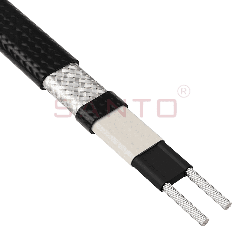
The SANTO UFA range of self-regulating heating cables is mainly used for frost protection of pipes and vessels but can also be used to maintain processes up to 65°C. These heating cables are available...
See Details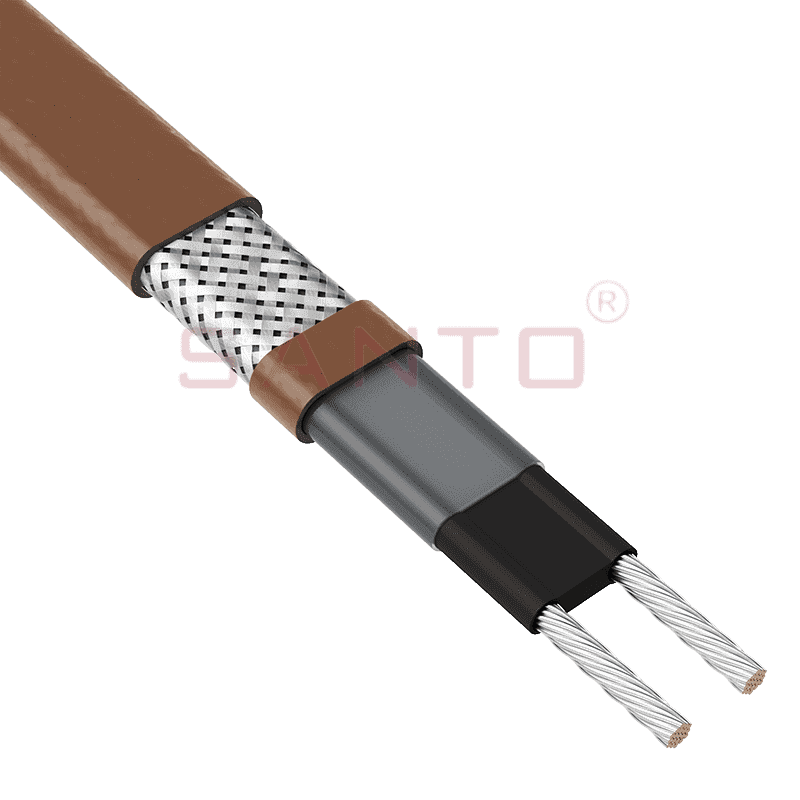
The SANTO UFB range of self-regulating heating cables is mainly used for frost protection of pipes and vessels requiring a higher power output than the UFA heating cables can supply. They can also be ...
See Details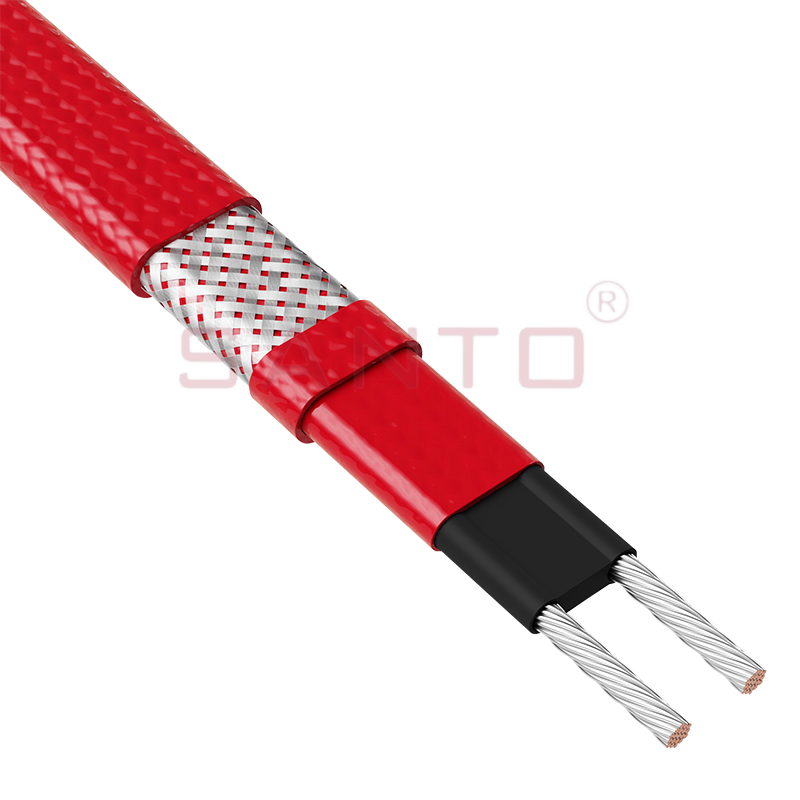
The SANTO UFC range of self-regulating heating cables is used for frost protection of pipes and vessels that require steam cleaning. They can also be used to maintain processes up to 121°C. These heat...
See Details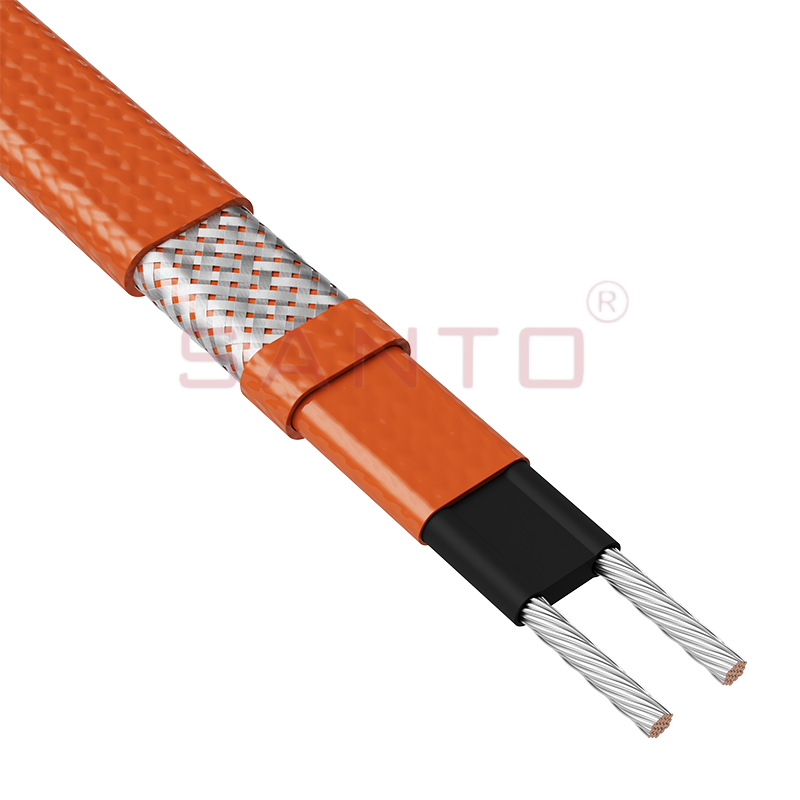
The SANTO UFO range of self-regulating heating cables is mainly used for frost protection of pipes and vessels that require steam cleaning . They can also be used to maintain processes up to 150°C. Th...
See Details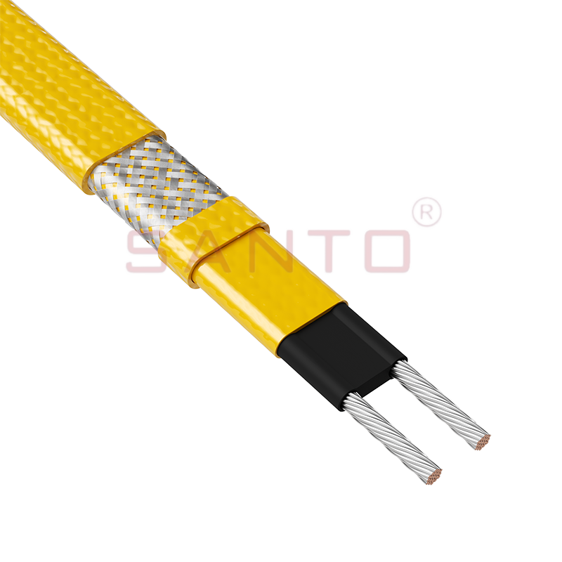
The SANTO UFD series of self-regulating heating cables are mainly used for freeze protection of pipes and vessels, but can also be used to maintain processes up to 200°C. These heating cables are avai...
See Details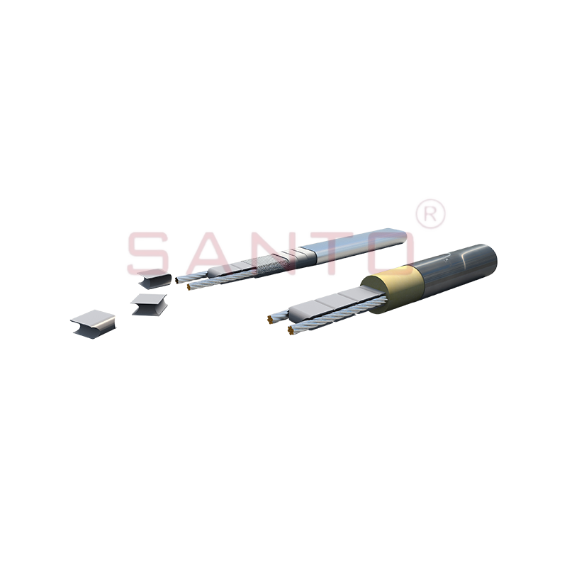
SANTO UFY heating wire is suitable for applications that maintain process temperatures up to 260 ℃ and can be steam blown; The self-regulating and parallel circuit heating wires of the UFY series are ...
See Details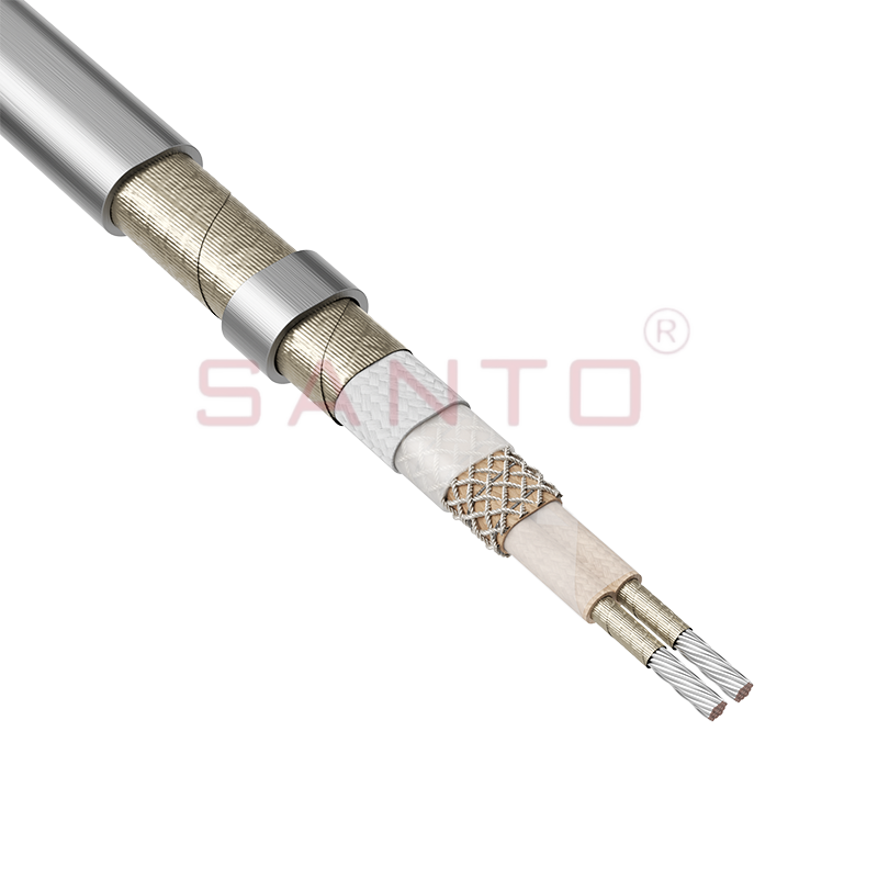
The SANTO UFM series self-regulating heating cables are mainly used for freeze protection of pipes and vessels, but can also be used to maintain processes up to 400°C. These heating cables are availab...
See Details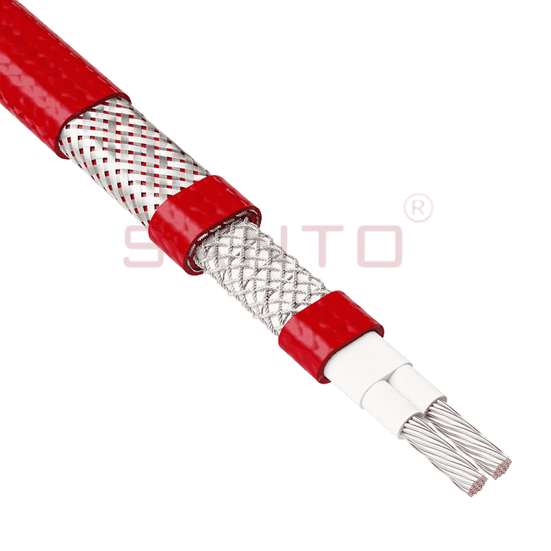
The SANTO ACC range of power-limiting heating cables is mainly used for temperature maintenance of processes and offers the advantage of a high power output at high temperatures which can reduce the n...
See Details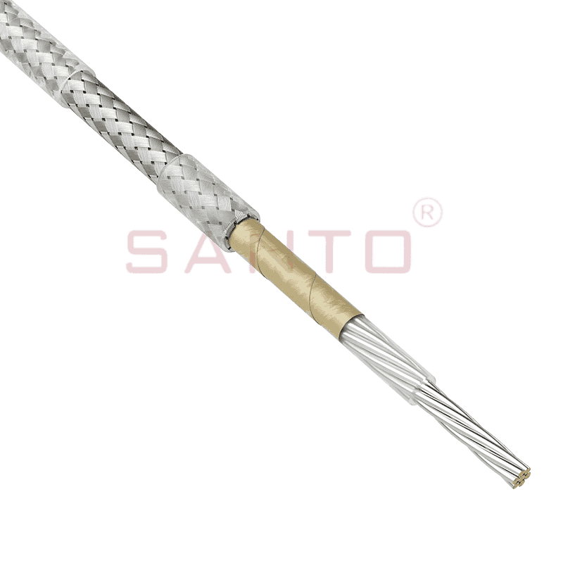
The stranded high temperature conductor is nickel plated to ensure a long life at elevated temperatures in corrosive environments. It is electrically isolated using an innovative sandwich construction...
See Details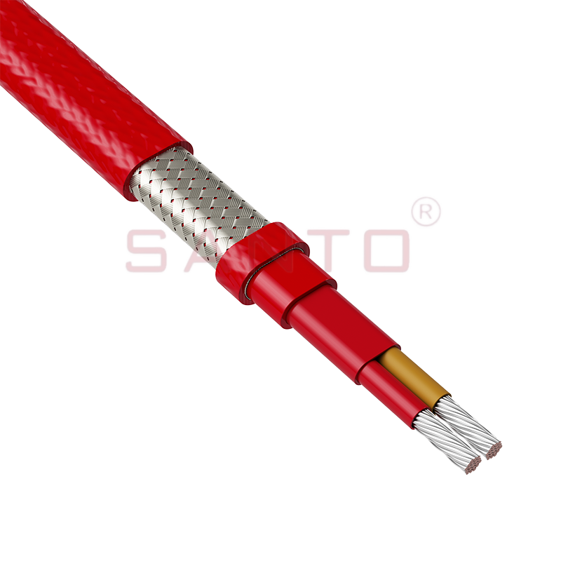
The stranded high temperature conductor is nickel plated to ensure a long life at elevated temperatures in corrosive environments. It is electrically isolated using an innovative sandwich construction...
See Details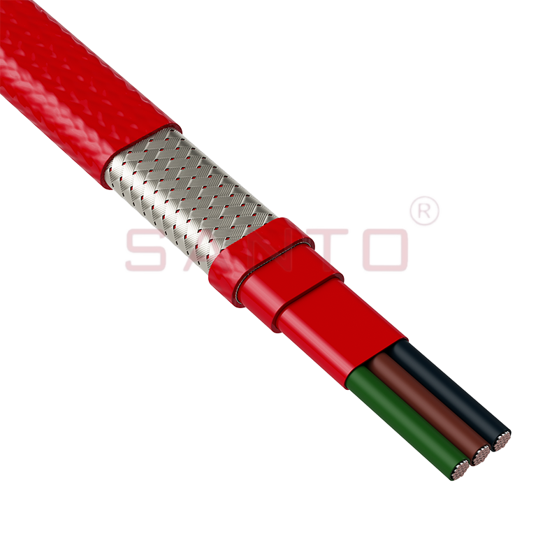
The stranded high temperature conductor is nickel plated to ensure a long life at elevated temperatures in corrosive environments. It is electrically isolated using an innovative sandwich construction...
See Details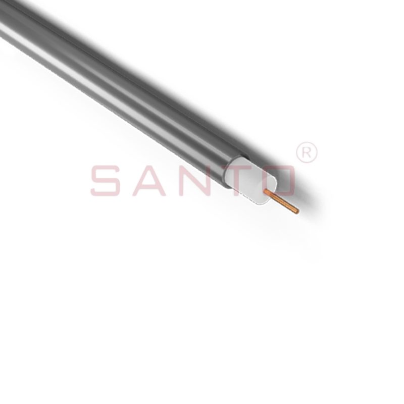
SANTO HAx mineral insulated (MI) Alloy 825 series heating cables are suitable for use in hazardous areas. They have been designed for use in freeze protection and temperature maintenance applications ...
See Details
Santo electric heating strips are widely used in key industries in China.

