 English
  English
 русский
 日本語
日本語 Español
 中文简体
中文简体
The SANTO UFA range of self-regulating heating cables is mainly used for frost protection of pipes and vessels but can also be used to maintain processes up to 65°C. These heating cables are available...
See Details
In heat-tracing installations, the junction point is one of the most important parts of the entire system. A heating cable may be correctly selected, accurately positioned, and properly controlled, yet the installation can still become unreliable if the connection between cable sections is poorly protected. Moisture penetration, loose conductors, mechanical damage, unsuitable sealing materials, or incorrect preparation can lead to electrical leakage, overheating, short circuits, or premature system failure. The JQH-LSC two-way junction box is designed to address these risks in self-regulating heating-wire applications.
The JQH-LSC is a dedicated power junction box for making a two-way connection between self-regulating heating wires. It is installed directly on the pipeline, with the thermal insulation layer fitted over the assembly after installation. The box provides an organized enclosure for the connection materials and helps protect the completed electrical joint from the surrounding installation environment. It is manufactured for use with heating systems that comply with applicable IEC requirements and can be used in Ex el hazardous areas when the complete installation meets the relevant certification, design, and operating conditions.
Unlike a general-purpose electrical enclosure, the JQH-LSC is developed around the special construction of self-regulating heating cables. These cables commonly include parallel busbars and a conductive polymer heating core. Preparing such cables requires careful removal of the outer jacket, insulation, and conductive material without damaging the busbars or allowing them to contact each other. The junction box, pressing plates, washers, pads, cover plates, and approved installation tapes work together to create a consistent and controlled connection arrangement.
This article explains the operating purpose, construction, installation considerations, safety requirements, manufacturing strengths, and application advantages of the JQH-LSC two-way junction box. It also compares the product’s specialized design with the limitations of improvised or generic junction solutions and provides a practical question-and-answer section for engineers, installers, maintenance teams, and purchasing personnel.
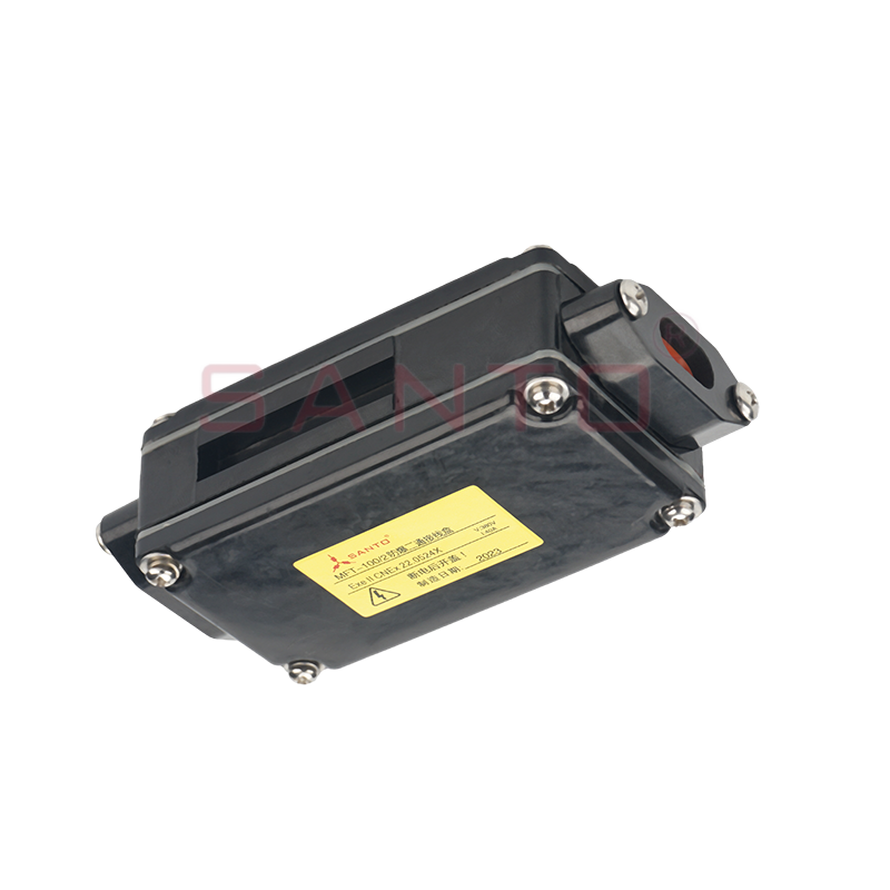
JQH-LSC two-way junction box
Content
Electric heat tracing is used to maintain the temperature of pipelines, tanks, valves, instruments, roofs, floors, and other surfaces. In many industrial installations, the heating cable is routed along a pipeline and connected to a power supply at a defined point. Depending on the design, a cable may also be extended, redirected, or connected to another section of heating cable. Every such connection must preserve electrical continuity, environmental protection, mechanical stability, and safe operation.
A junction box is therefore more than a container. It is a controlled working area for preparing and securing the cable connection. It must accommodate the connection components, provide adequate space for cable preparation, support the connected cable, and allow the finished joint to remain protected after the insulation system is applied. The enclosure should also help prevent accidental contact between conductive parts and should be compatible with the temperature, moisture, chemical, and mechanical conditions of the installation.
Self-regulating heating wires require particular attention because their heating output changes according to the temperature around the cable. The conductive polymer core expands and contracts electrically as temperature changes, while the parallel busbars carry current along the cable. If the busbars are cut, scratched, compressed incorrectly, or allowed to touch one another, the heating circuit can be damaged. If the black conductive plastic is exposed or insufficiently insulated, leakage or short-circuit hazards may develop.
The JQH-LSC provides a purpose-designed location for this work. By placing the two-way connection inside a dedicated box, the installer can follow a defined preparation method rather than attempting to make the connection in an uncontrolled area. The cover plates and fasteners help retain the completed arrangement, while the pressing plates and red washers help secure and isolate the connection components. The box is subsequently integrated into the pipeline insulation system.
The JQH-LSC is a two-way junction box intended for self-regulating heating wires. It is categorized as a power junction box and is used for two-way connection work during the installation of electric heat-tracing systems. The product is fixed on the pipeline, and an insulation layer is installed on the outside after the junction has been completed.
The main function of the product is to hold the materials used for the two-way connection in a protected and organized enclosure. This arrangement improves installation consistency and helps reduce the possibility of exposed conductors, misplaced connection parts, or accidental damage during the application of the insulation layer.
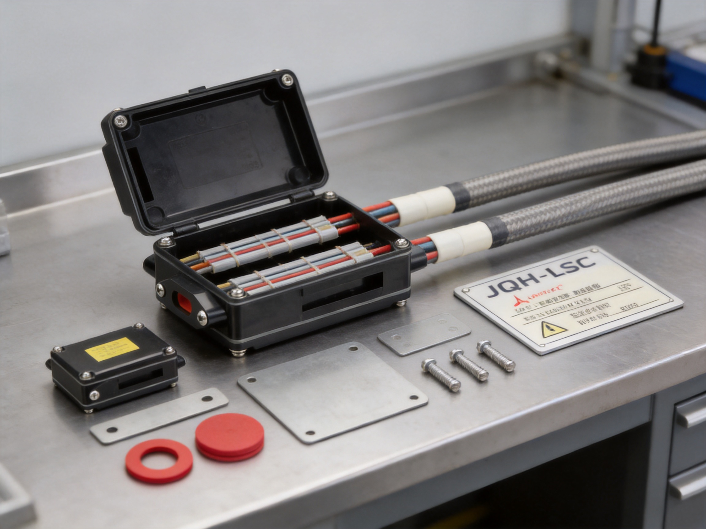
The box is supplied with a group of internal components designed to support the connection procedure. These components include the cassette, pressing plates with screws, red washers, pads, cover plates with screws, and a nameplate. The supplied parts are matched to the enclosure and are intended to be used together as a complete assembly.
| Item | Quantity | Component | Primary Function |
|---|---|---|---|
| A | 1 | Cassette | Provides the main internal support and connection area |
| B | 3 | Pressing plates with screws | Helps secure prepared cable sections and connection materials |
| C | 3 | Red washers | Supports separation, positioning, and insulation of connection parts |
| D | 2 | Pads | Provides additional support within the assembly |
| E | 2 | Cover plates with screws | Closes and protects the internal arrangement |
| F | 1 | Nameplate | Identifies the junction box and installation information |
The combination of these parts allows the installer to perform the connection in a repeatable sequence. The components are not intended to be replaced with unrelated hardware. Standard-approved parts should be used to preserve the designed electrical and mechanical characteristics of the junction box.
One of the main advantages of the JQH-LSC over a generic junction enclosure is that its design reflects the physical structure of self-regulating heating cable. A general electrical box may provide space, but it does not necessarily provide the correct arrangement for handling parallel busbars, conductive plastic, cable insulation, pressing plates, and sealing materials.
Self-regulating cable preparation must be performed carefully. The outer protective layer is removed to expose the inner structure. The conductive plastic is then prepared according to the connection method, while the busbars are preserved and kept separate. Any cut or scrape that reaches a busbar can weaken the conductor or create a localized hot spot. The JQH-LSC installation method emphasizes this risk and provides an enclosure in which the prepared cable ends can be arranged and retained.
The cassette gives the internal assembly a defined location. The pressing plates and screws help prevent movement after the connection has been prepared. The red washers and pads support separation and positioning. The cover plates provide a final layer of physical protection. This is especially important when thermal insulation, cladding, weatherproofing, or other finishing materials are installed around the pipeline.
The product also helps establish a clear boundary between the heating cable connection and the pipeline surface. Proper positioning reduces the likelihood that the cable will be sharply bent, crushed, or pulled during the insulation process. A controlled enclosure can also make future inspection and maintenance easier than a connection buried without a clear junction location.
Generic electrical junction boxes are often designed for ordinary cable termination rather than heat-tracing cable preparation. Their internal terminals, cable entries, and mounting arrangements may not accommodate the structure of self-regulating heating wires. The JQH-LSC is specifically intended for this type of connection, so the internal components and installation sequence are aligned with the needs of heating-wire systems.
The black conductive plastic used in a self-regulating heating wire must be insulated correctly, and the busbars must not contact one another. The dedicated components supplied with the JQH-LSC help the installer maintain separation and organize the prepared cable. This is a practical advantage over improvised arrangements using loose insulating materials, ordinary terminal blocks, or non-approved tapes.
When a heating project contains hundreds or thousands of connection points, repeatability has a direct effect on system reliability. A purpose-designed box provides the same basic enclosure, component layout, and fastening method at every location. This reduces variation between installers and makes quality inspection more straightforward.
The junction box is intended to be fixed on the pipeline and covered externally by the insulation layer. This makes it suitable for common industrial heat-tracing construction in which the heating cable is installed first and the insulation and protective cladding are applied afterward. Its design supports a planned junction location rather than leaving the connection exposed or loosely positioned beneath the insulation.
The product can be used in Ex el hazardous areas, subject to the requirements of the complete project design and the relevant approval conditions. This provides an important advantage for applications involving petroleum, chemical processing, gas facilities, storage areas, and other locations where electrical equipment must be selected and installed according to hazardous-area rules.
Hazardous-area suitability does not eliminate the need for correct installation. Cable type, power supply, protective devices, temperature classification, grounding, sealing, inspection, and operating conditions must all be evaluated. Nevertheless, a junction box designed for the intended environment provides a stronger foundation than a non-specialized enclosure.
The installation instructions specify approved components and tapes. This is important because ordinary PVC insulation tape may not provide the required thermal, electrical, or environmental performance. The JQH-LSC package gives the installer a defined set of parts and helps prevent the use of materials that are convenient but unsuitable for heat-tracing service.
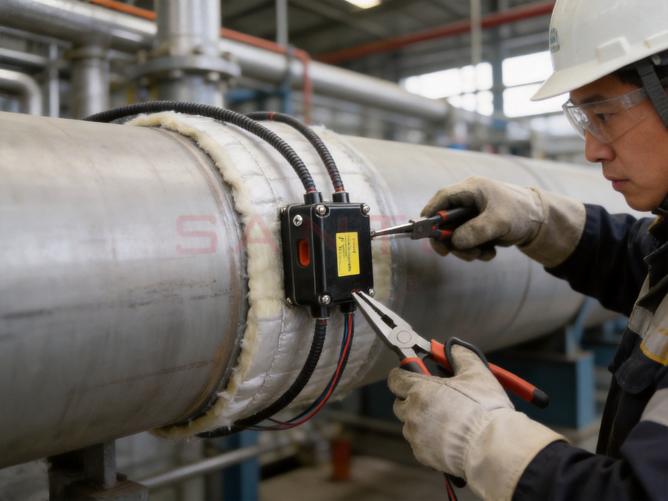
The recommended tools for installing the JQH-LSC include wire pliers, pointed pliers, a special tool knife, and a screwdriver. Each tool serves a different purpose in the preparation and assembly procedure.
Wire pliers are used for controlled handling and cutting operations where permitted by the installation method. Pointed pliers assist with positioning and manipulating small components or prepared cable sections. The special tool knife is used to remove selected layers of the heating cable. Because the busbars must not be scratched or cut, the knife must be handled with precision and should be suitable for controlled insulation stripping. The screwdriver is used to tighten the screws in the pressing plates and cover plates.
The installation also requires Peitu 41 tape. The supplied information identifies two relevant tape options. GT-66 is used for installation temperatures above 4 degrees Celsius, while GS-54 is used for installation temperatures above -40 degrees Celsius. The installer should select the tape according to the actual working temperature and the applicable installation instructions.
| Tool or Material | Use in the Installation | Important Consideration |
|---|---|---|
| Wire pliers | Handling and approved cable preparation operations | Do not crush or damage the busbars |
| Pointed pliers | Positioning small parts and prepared cable sections | Use controlled force to avoid deforming components |
| Special tool knife | Removing cable layers | Do not scratch or cut the busbars |
| Screwdriver | Securing pressing plates and cover plates | Tighten correctly without damaging screws or enclosure |
| GT-66 tape | Installation above 4 degrees Celsius | Use only within its specified temperature range |
| GS-54 tape | Installation above -40 degrees Celsius | Confirm compatibility with the actual site conditions |
Before beginning work, the installer should confirm that all components are present, clean, dry, and free from damage. The work area should be protected from rain, condensation, dust, oil, and other contaminants. The cable end and the internal box components should remain dry throughout the preparation process.
The exact installation procedure must follow the product’s official installation manual and the design documents for the heating system. The following sequence describes the general principles that should be observed when installing a JQH-LSC two-way junction box.
Select a suitable location on the pipeline according to the heat-tracing layout. The location should provide sufficient working space for cable preparation and box assembly. It should also allow the box to remain accessible during installation and inspection before the insulation layer is closed.
Confirm that the heating cable length, routing direction, and connection arrangement correspond to the approved drawings. The cable should not be placed under excessive tension, and the selected point should not force a sharp bend or an unsafe mechanical arrangement.
Inspect the heating cable for cuts, crushing, moisture, contamination, or other visible damage. Check the cassette, pressing plates, red washers, pads, cover plates, screws, and nameplate. Do not use damaged or missing components. Confirm that the appropriate approved tape is available for the installation temperature.
Use the special tool knife to remove the required outer layers in accordance with the installation manual. The purpose of this operation is to expose the connection area without damaging the internal conductors. The black conductive plastic should be handled carefully and should not be left exposed without the required insulation treatment.
Particular care is required when working near the busbars. The busbars must remain intact and must not be scratched, nicked, or cut. A damaged busbar can increase resistance, create a weak point, or contribute to overheating. The two busbars must also remain electrically separated throughout the preparation process.
Place the prepared cable sections into the cassette and arrange them according to the connection design. Avoid forcing the cable into the box or bending it more tightly than permitted. The cable should be supported so that movement is minimized during the remaining assembly steps.
Fit the pressing plates, red washers, and pads in their intended locations. The components should be clean and correctly oriented. Tighten the screws using the appropriate screwdriver and a controlled method. Over-tightening may damage the cable, plates, screws, or enclosure, while insufficient tightening may permit movement or reduce mechanical stability.
Use the specified Peitu 41 tape or other approved material according to the installation instructions. Do not substitute PVC insulation tape or unapproved sealing products. The tape must be applied to clean, dry surfaces and should be installed at a temperature within its specified range.
Install the cover plates and secure their screws. The cover should sit correctly and should not pinch or deform the heating cable. Attach the nameplate as required by the project documentation. Identification is valuable for commissioning, inspection, troubleshooting, and future maintenance.
After the electrical connection has been inspected and accepted, install the external thermal insulation and protective cladding. The insulation should not place excessive mechanical pressure on the junction box or heating cable. The final construction should protect the box from water ingress, impact, and environmental exposure in accordance with the system design.
The JQH-LSC is an electrical component and must be installed and operated correctly. Fire resistance and electrical safety must be considered throughout the work. The installer should read the precautions and installation manual before beginning the connection procedure.
A leakage protection device should be installed to reduce the risk of fire caused by damage, moisture, or improper installation of the heating wire. The protective device should be selected and coordinated with the electrical design, power supply, cable characteristics, and applicable regulations. Testing should be completed before the system is energized.
Only standard-approved components should be used. Substitutes can change the electrical insulation, thermal behavior, mechanical strength, or environmental resistance of the connection. Ordinary PVC insulation tape must not be used as a replacement for the specified installation materials.
The black conductive plastic in the heating cable must be kept strictly insulated and dry. It should not be left exposed to moisture, conductive contamination, or accidental contact with the busbars. The connection area must remain clean during assembly, and any contamination should be removed using a method approved for the cable and components.
When stripping the insulation or conductive plastic, do not scratch the busbar. Even a small defect may affect the conductor’s performance or create a localized heating point. The busbars must never touch one another. Accidental contact can result in a short circuit and may cause immediate damage when power is applied.
Before energizing the system, the installer should carry out the prescribed visual, continuity, insulation-resistance, and protective-device checks. In hazardous areas, additional inspection and documentation may be required. Testing must be performed by qualified personnel using instruments suitable for the heating cable and installation environment.
Heat tracing is frequently applied in locations where flammable liquids, gases, vapors, or dusts may be present. In such environments, electrical equipment must be selected and installed to limit the possibility of ignition. The JQH-LSC can be used in Ex el hazardous areas, but the box must always be treated as one part of a certified and engineered system.
The hazardous-area design should consider the zone or area classification, gas or dust group, temperature class, ambient temperature, power supply arrangement, cable surface temperature, protective devices, grounding, and enclosure installation. The heating cable itself must be suitable for the area, and the junction connection must be installed according to the relevant certification and project instructions.
Installation records should identify the heating circuit, junction-box location, cable type, supply information, test results, and inspection status. Clear records are particularly important in hazardous facilities because later maintenance personnel need to understand the original design and verify that replacement materials remain approved.
The use of an application-specific junction box helps reduce uncertainty during this process. It gives the project team a defined product with a known component list and a repeatable installation approach. However, no enclosure can compensate for incorrect cable selection, unsuitable sealing, poor grounding, unauthorized modification, or failure to follow hazardous-area requirements.
The JQH-LSC is part of a wider electric heating product portfolio manufactured by Santo Thermal Control Technology Co., Ltd. The company specializes in electric heating and heat-tracing products, including self-regulating heating belts, constant-power heating belts, silicone rubber heating belts, glass-fiber heating belts, mineral-insulated cables, snow-melting cables, and related accessories.
A junction box for heating cables benefits from the manufacturer’s experience across the complete heat-tracing system. Understanding the cable structure, temperature behavior, insulation requirements, installation methods, and field conditions allows the junction enclosure to be developed as part of a system rather than as an isolated box.
The company operates in Jiangsu Province, an area recognized for electric heating belt manufacturing. Its reported capabilities include product research, design, production, manufacturing, sales, technical guidance, and after-sales service. This integrated structure can shorten communication paths between product development, production, quality control, and customer support.
The company reports more than 35 years of industry experience, annual output exceeding 10,000 units or products across its business scope, more than 2,000 distributors, and business coverage in more than 85 areas. These figures indicate experience in serving varied applications and distribution channels. For buyers, an established production background can be valuable when consistent supply, documentation, customization, and technical response are required.
The company also reports ISO9001 quality-system certification and national CCC certification for its products. Certification does not replace project-specific verification, but it demonstrates the use of a formal quality-management framework and an established approach to product control.
According to the company’s development history, its activities began with the establishment of an electric heating instrument factory in 2000. The organization later passed ISO9001:2000 quality-system certification, established an irradiation center, developed high-temperature self-limiting and far-infrared heating technologies, and introduced additional heating cable designs.
The company reports cooperation in product research with Harvard University in the United States and describes continued development in self-limiting temperature technology, carbon-fiber parallel heating cables, and other electrical heating products. Such research experience is relevant to accessories because reliable junctions must reflect the electrical and physical characteristics of the cables with which they are used.
Modern manufacturing control for a junction box should begin with material verification. Enclosure materials, insulating components, screws, washers, pads, tapes, and labels must meet defined specifications. Incoming inspection can identify dimensional variation, surface defects, material inconsistency, or missing components before assembly.
During production, controlled assembly procedures help ensure that the cassette, pressing plates, washers, pads, cover plates, and nameplate are correctly matched. Fastener installation should be consistent, and visual inspection should confirm that the enclosure is clean, undamaged, and properly closed. Where applicable, electrical, dimensional, mechanical, and environmental tests should be incorporated into the quality plan.
Traceability is another important manufacturing strength. Batch identification, production records, inspection reports, and packaging controls allow the manufacturer to investigate issues and support customers with replacement or technical information. This is especially useful for large projects in which junction boxes are installed across multiple buildings, process units, or pipeline sections.
Reliability in heat tracing depends on the complete system, but the junction point is a high-value area for quality control. A poorly prepared connection can fail even when the heating cable is undamaged. The JQH-LSC supports reliability by giving the installer a defined enclosure, a consistent set of components, and a clear list of precautions.
Mechanical stability is important because pipeline systems experience thermal expansion, vibration, maintenance activity, and environmental movement. The pressing plates and cover plates help hold the connection arrangement in place. By limiting unwanted movement, they reduce stress on the prepared cable and connection materials.
Electrical separation is equally important. The red washers, pads, insulation materials, and enclosure arrangement help the installer keep conductive parts in their intended positions. The product’s instructions also emphasize that the conductive plastic must remain insulated and that the busbars must not contact each other.
Environmental protection is achieved through the combination of the junction box, approved tape, careful installation, and the completed insulation system. The box alone should not be considered a substitute for correct sealing or external weather protection. When installed as designed, however, it gives the connection a defined protective structure and helps prevent accidental exposure.
Maintenance efficiency is another practical advantage. A clearly identified junction box can be located more easily during inspection. The nameplate can support circuit identification and reduce the time required to trace a heating cable beneath insulation or cladding. For industrial operators, improved traceability can reduce downtime during troubleshooting.
Pipeline systems in petroleum and chemical facilities often require freeze protection or process-temperature maintenance. The JQH-LSC can be used to organize two-way connections in self-regulating heat-tracing circuits installed on process lines, transfer lines, drains, and associated equipment, provided the cable and junction arrangement meet the project requirements.
Gas-processing and gas-distribution facilities may require heating to prevent freezing, condensation, or viscosity-related problems. Because these sites can include hazardous areas, the use of an appropriate junction box and approved installation method is especially important.
Outdoor energy systems may experience low temperatures, snow, ice, or moisture. Heat tracing can protect water lines, drainage systems, process piping, and equipment. The JQH-LSC offers a structured connection approach for self-regulating cables in locations where reliable installation and clear identification are needed.
Commercial and industrial buildings use heat tracing for roof drainage, gutters, water pipes, fire-protection lines, loading areas, and exposed plumbing. The junction box can help installers create organized connections while the surrounding insulation or protective construction is completed.
Geothermal cultivation, greenhouse systems, and agricultural process equipment may require temperature maintenance for pipes and tanks. In these applications, the junction box can support controlled installation and future service work, particularly where circuits are distributed over large areas.
Heat-tracing technology is also used for snow melting and ice prevention. Although the JQH-LSC is intended for self-regulating heating-wire connections, the suitability of the box must always be confirmed against the cable type, environmental exposure, electrical load, and installation design.
Before specifying the JQH-LSC, engineers should confirm that the heating cable is a self-regulating type compatible with the junction-box connection method. The circuit voltage, maximum operating current, cable dimensions, minimum installation temperature, environmental conditions, and hazardous-area classification should be reviewed.
The number and location of junction boxes should be shown on the heat-tracing drawings. Each box should be positioned where it can be installed, inspected, and identified without creating unnecessary bends or mechanical stress in the cable. The design should also account for valves, flanges, supports, expansion joints, instrumentation, and removable insulation sections.
Thermal insulation thickness and cladding design should be coordinated with the junction box. The completed insulation must not compress the assembly in a way that damages the cable or cover. At the same time, the junction point should remain adequately integrated with the insulation system so that the pipeline does not develop an excessive cold spot.
For hazardous-area projects, the specification should identify the required certificates, permitted cable accessories, enclosure limitations, grounding method, inspection requirements, and repair procedures. Procurement teams should request the relevant technical documentation and confirm that the product configuration matches the project’s approval requirements.
| Selection Area | Questions to Confirm |
|---|---|
| Heating cable | Is the cable self-regulating and compatible with the connection method? |
| Electrical design | Are voltage, current, circuit length, and protective devices suitable? |
| Environment | Are temperature, moisture, chemicals, vibration, and outdoor exposure considered? |
| Hazardous area | Does the complete installation meet the required Ex classification? |
| Installation temperature | Is the correct approved tape selected for the site temperature? |
| Insulation | Can the external insulation be installed without damaging the junction assembly? |
| Maintenance | Are junction locations identified and accessible for inspection? |
| Documentation | Are installation manuals, certificates, test records, and drawings available? |
Heating cable accessories are sometimes treated as minor items compared with the cable itself. In practice, accessories have a major effect on the performance of the completed system. A cable can only deliver dependable service if its power connection, end termination, splice, junction, control equipment, and protection devices are all correctly selected.
The JQH-LSC demonstrates the value of a complete accessory approach. The cassette, pressing plates, washers, pads, cover plates, screws, nameplate, and approved tapes are considered together. This reduces the need for the installer to create an assembly from unrelated parts and helps maintain the intended relationship between mechanical support and electrical insulation.
A complete accessory package also simplifies purchasing and project planning. The customer can specify one product for a defined two-way connection function instead of sourcing an enclosure, hardware, insulation materials, and labels separately. This can reduce procurement errors and make warehouse control easier.
For international projects, standardized accessories can also help distributors and contractors support multiple markets. The manufacturer’s broader experience with export sales, distributors, and international product development provides a useful foundation for technical communication and supply coordination.
Inspection should begin before installation. The box and all components should be checked for damage, contamination, deformation, or missing parts. The heating cable should be inspected for damage caused during transportation or handling. Any discrepancy should be recorded and resolved before the connection is prepared.
During installation, inspectors should verify cable stripping, busbar condition, conductive-plastic insulation, component placement, screw installation, tape application, cover installation, and nameplate identification. Photographs or inspection records may be useful before the external insulation hides the junction box.
Electrical testing should follow the heating-system design and the manufacturer’s instructions. Typical checks may include conductor continuity, insulation resistance, resistance-to-ground, leakage-protection operation, and functional operation of the control system. The test voltage and procedure must be suitable for the particular heating cable and should be performed by qualified personnel.
After commissioning, maintenance teams should inspect accessible junction points for signs of moisture, mechanical damage, overheating, corrosion, loose covers, or damaged insulation. If a fault is detected, the circuit should be isolated before the junction box is opened. Repairs should use approved replacement components and should follow the original installation method.
In hazardous areas, maintenance work must comply with site permits, isolation procedures, gas testing, and equipment-control rules. Unauthorized modification of the junction box or substitution of components can invalidate the installation approval and introduce serious safety risks.
Heat-tracing projects vary widely. A small building application may require only a few junctions, while a chemical plant may require a large quantity of boxes with detailed documentation and project labeling. A manufacturer with experience in research, production, export sales, and technical service can support these different requirements more effectively than a supplier focused only on commodity enclosures.
The company behind the JQH-LSC provides electric heating products for petroleum, chemical, gas, construction, solar energy, geothermal cultivation, and other sectors. Its product range allows customers to discuss junction boxes alongside heating cables, snow-melting products, silicone rubber heating systems, mineral-insulated cables, and other accessories.
For OEM and ODM customers, technical discussions may include product labeling, packaging, documentation, project quantities, accessory combinations, installation temperatures, and application conditions. Any customization should be reviewed carefully to ensure that it does not alter the product’s safety or approval characteristics.
Customers can contact the supplier through its published telephone and email channels for product inquiries, technical information, quotation requests, and project support. Before ordering, buyers should provide the heating cable model, installation environment, required quantity, operating temperature, area classification, and documentation requirements.
Contractors benefit from products that reduce uncertainty at the work site. The JQH-LSC includes a defined component set, identifies the required tools, and specifies the approved tape options for different installation temperatures. These details support work preparation and reduce the risk that crews will arrive without essential materials.
The organized enclosure also helps improve workmanship. Cable preparation can be performed in a stable location rather than on an exposed pipeline surface. Components are less likely to be lost, and the finished connection is easier to inspect before insulation is installed.
Training is simplified when installers use the same product and method across multiple projects. Supervisors can develop standard inspection checklists covering the same critical points: no busbar damage, no busbar contact, dry conductive plastic, correct component placement, correct tape, secure screws, closed cover, and completed identification.
These practical benefits can translate into lower rework rates and more predictable installation schedules. In large projects, avoiding even a small number of concealed connection failures can save considerable labor, insulation-removal costs, troubleshooting time, and production disruption.
Facility owners require heating systems that remain dependable over many operating seasons. The JQH-LSC contributes to this objective by supporting a controlled connection method and by making junction locations easier to identify. A clear and serviceable installation can improve maintenance planning and reduce the time needed to investigate a cold pipeline or failed heating circuit.
The product is also suitable for integration into broader heat-tracing quality programs. Owners can include the junction box in their approved-material lists, inspection procedures, spare-parts schedules, and maintenance documentation. This creates consistency between new installations and later repairs.
For facilities with hazardous-area requirements, an approved and documented connection method is particularly valuable. The product does not replace a complete hazardous-area engineering review, but it supports a more disciplined approach to accessory selection and installation control.
One common error is using a substitute tape or an ordinary PVC insulation tape. Such materials may not have suitable temperature, insulation, adhesion, or environmental properties. The specified approved tape should be used instead.
Another error is cutting too deeply into the cable while removing the outer layers. The special tool knife should be used carefully, and the busbars should be checked after preparation. If a busbar has been scratched or damaged, the cable section should not be energized without technical evaluation.
Installers must also avoid allowing the busbars to touch. This can happen when the cable end is prepared too aggressively, when conductors are not positioned correctly, or when a pressing component is installed incorrectly. A visual check should be completed before the cover is fitted.
Moisture is another serious risk. The conductive plastic and connection area must remain dry. Installation should be postponed or protected if rain, condensation, flooding, or high humidity could contaminate the work. The insulation layer should not be installed until the connection has been inspected and accepted.
Finally, the junction box should not be forced into an unsuitable location. Sharp cable bends, excessive pulling, compression by cladding, and inaccessible placement can all reduce long-term reliability. The box must be coordinated with the pipeline layout and insulation design.
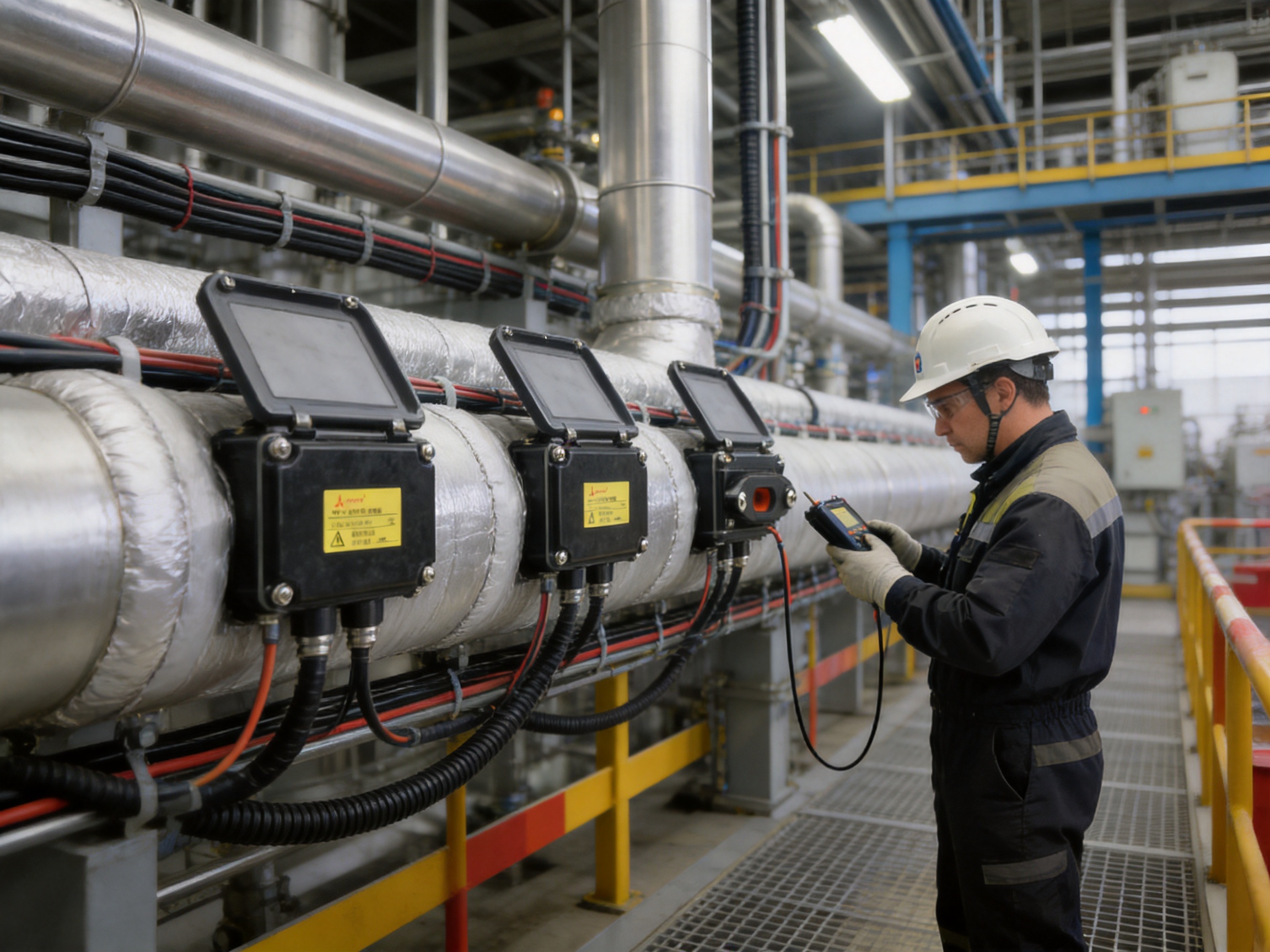
It is used to make a two-way connection for self-regulating heating wires. The connection materials are placed inside the box, which is fixed on the pipeline and covered externally by the thermal insulation system.
The product is intended for self-regulating heating wires. Compatibility should be confirmed against the cable construction, dimensions, voltage, current, installation method, and project documentation before use.
The JQH-LSC can be used in Ex el hazardous areas when the complete system satisfies the relevant certification and project requirements. The cable, power supply, protective devices, temperature classification, grounding, sealing, and installation method must also be suitable.
The listed tools are wire pliers, pointed pliers, a special tool knife, and a screwdriver. The installer may need additional site-specific equipment for electrical testing, access, isolation, and inspection.
GT-66 is identified for installation temperatures above 4 degrees Celsius. GS-54 is identified for installation temperatures above -40 degrees Celsius. The installer should verify the actual temperature range and follow the official installation instructions.
No. The installation precautions specify that only standard-approved components should be used and that PVC insulation tape must not replace the approved materials.
A scratch or cut can damage the conductor, increase electrical resistance, create a weak point, or contribute to localized overheating. The busbars must remain intact and separated from one another.
The conductive plastic forms part of the heating element and must be properly insulated. Moisture or contamination in the connection area may reduce insulation performance, increase leakage current, or contribute to short circuits.
No. The box is installed on the pipeline and the insulation layer is fitted outside it. The junction box and the thermal insulation system perform different functions and must be installed together according to the design.
Testing should follow the heating-system design and official installation instructions. Qualified personnel should perform appropriate continuity, insulation, grounding, leakage-protection, and functional checks before energization.
Confirm the heating cable type, circuit voltage, operating conditions, installation temperature, environmental exposure, hazardous-area classification, quantity, documentation requirements, and compatibility with the intended connection method.
A dedicated junction box provides components and an arrangement designed for self-regulating heating-wire connections. It improves repeatability, conductor separation, mechanical support, inspection, and integration with the pipeline insulation system.
The JQH-LSC two-way junction box is a specialized accessory for self-regulating heat-tracing systems. Its purpose-built cassette, pressing plates, red washers, pads, cover plates, screws, and nameplate create a controlled connection environment that is more suitable for heating wires than an improvised or generic enclosure.
Its main advantages include organized cable preparation, support for conductor separation, improved installation repeatability, compatibility with insulated pipeline construction, suitability for Ex el hazardous-area applications when properly engineered, and the use of an approved component set. These benefits help protect the connection from electrical, mechanical, and environmental risks.
The product is supported by a manufacturer with broad experience in electric heating research, design, manufacturing, quality management, export sales, and technical service. The company’s wider product portfolio and reported certifications provide a foundation for supplying complete heat-tracing solutions to industrial and commercial customers.
Correct installation remains essential. The heating cable must be prepared without damaging the busbars, the conductive plastic must remain insulated and dry, the busbars must not contact one another, approved materials must be used, and leakage protection and testing must be provided. When these requirements are followed, the JQH-LSC can contribute to a safer, more maintainable, and more reliable heat-tracing installation.
1. IEC standards and accepted engineering practices for electrical heat-tracing systems and industrial electrical installations.
2. JQH-LSC Two-Way Junction Box product information and component list supplied by the manufacturer.
3. Manufacturer’s installation precautions for self-regulating heating-wire connections.
4. Manufacturer’s technical information for Peitu 41 tape, GT-66, and GS-54 installation materials.
5. General principles of hazardous-area electrical equipment selection, installation, inspection, and maintenance.
6. ISO 9001 quality-management principles for controlled manufacturing and product traceability.
7. Technical documentation and application guidance for self-regulating electric heat-tracing cables.
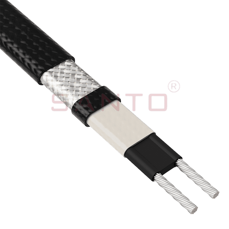
The SANTO UFA range of self-regulating heating cables is mainly used for frost protection of pipes and vessels but can also be used to maintain processes up to 65°C. These heating cables are available...
See Details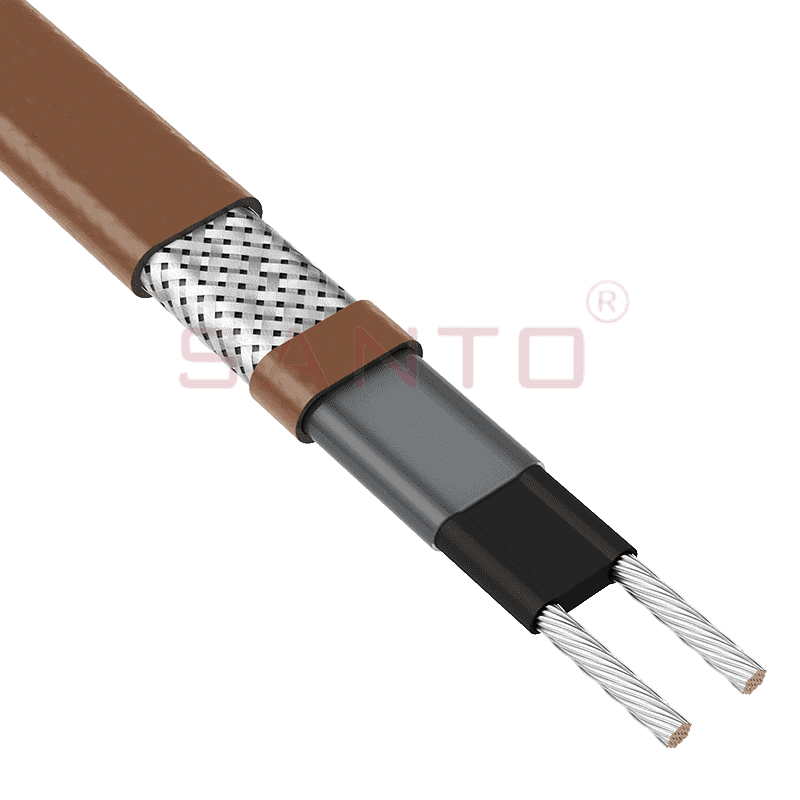
The SANTO UFB range of self-regulating heating cables is mainly used for frost protection of pipes and vessels requiring a higher power output than the UFA heating cables can supply. They can also be ...
See Details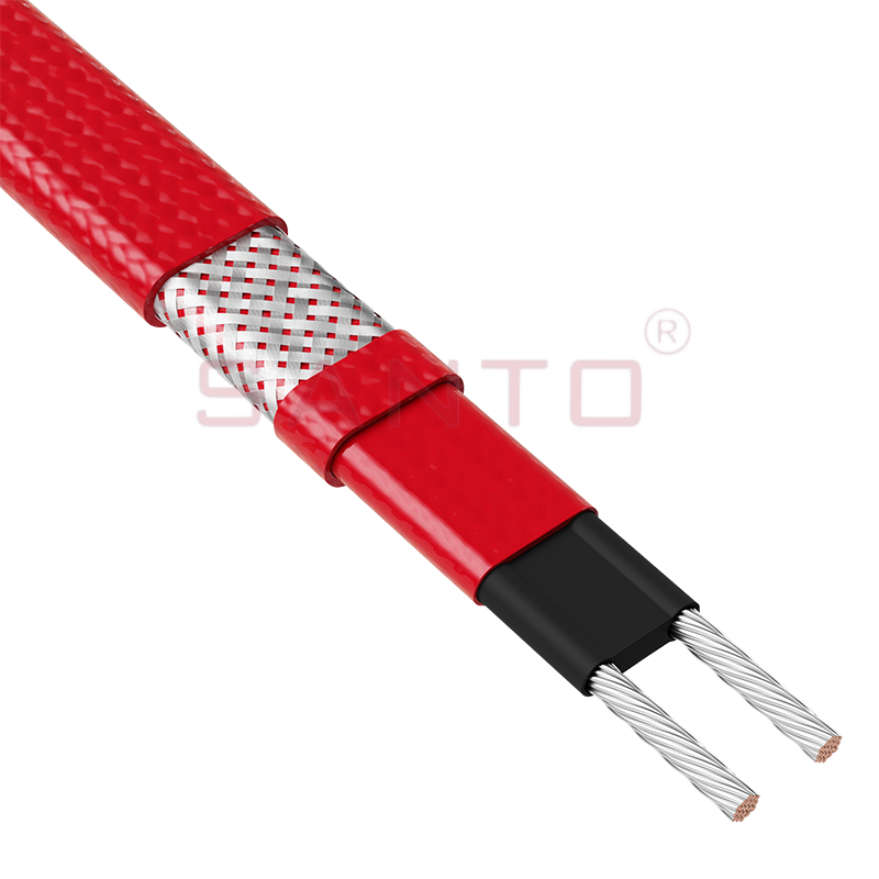
The SANTO UFC range of self-regulating heating cables is used for frost protection of pipes and vessels that require steam cleaning. They can also be used to maintain processes up to 121°C. These heat...
See Details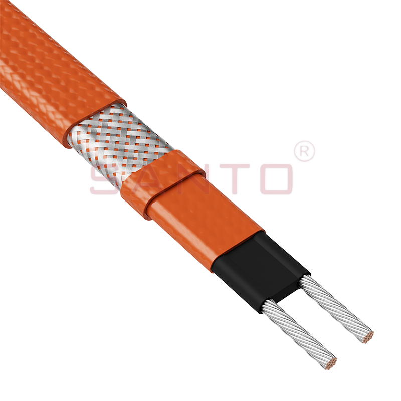
The SANTO UFO range of self-regulating heating cables is mainly used for frost protection of pipes and vessels that require steam cleaning . They can also be used to maintain processes up to 150°C. Th...
See Details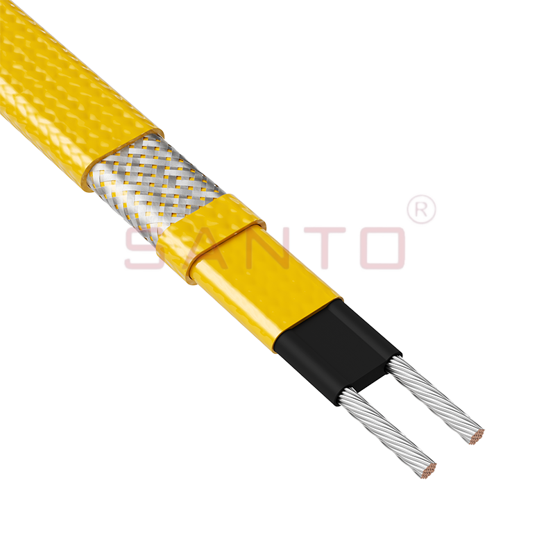
The SANTO UFD series of self-regulating heating cables are mainly used for freeze protection of pipes and vessels, but can also be used to maintain processes up to 200°C. These heating cables are avai...
See Details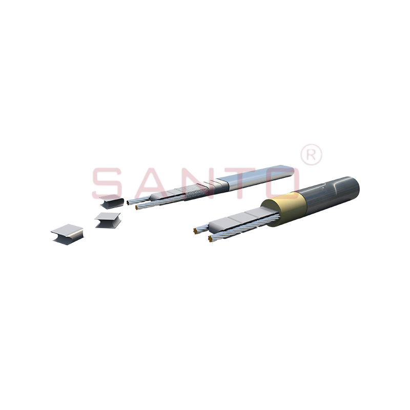
SANTO UFY heating wire is suitable for applications that maintain process temperatures up to 260 ℃ and can be steam blown; The self-regulating and parallel circuit heating wires of the UFY series are ...
See Details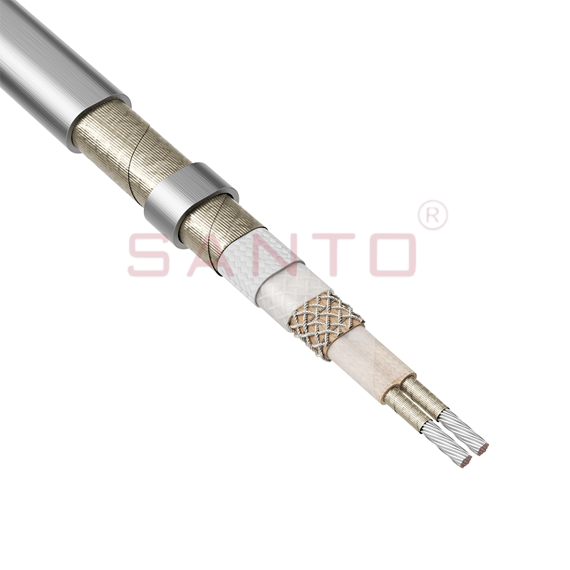
The SANTO UFM series self-regulating heating cables are mainly used for freeze protection of pipes and vessels, but can also be used to maintain processes up to 400°C. These heating cables are availab...
See Details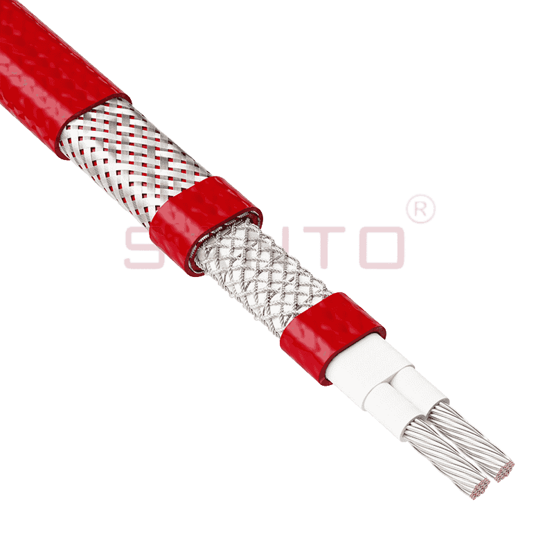
The SANTO ACC range of power-limiting heating cables is mainly used for temperature maintenance of processes and offers the advantage of a high power output at high temperatures which can reduce the n...
See Details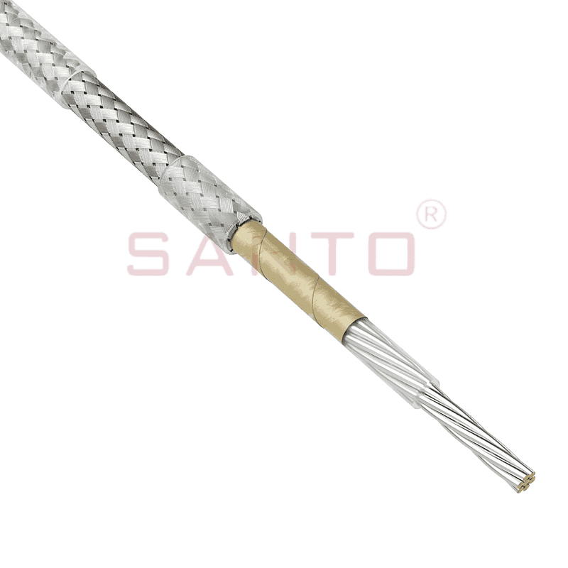
The stranded high temperature conductor is nickel plated to ensure a long life at elevated temperatures in corrosive environments. It is electrically isolated using an innovative sandwich construction...
See Details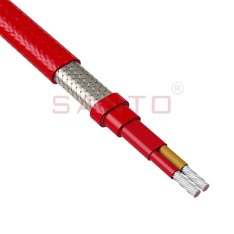
The stranded high temperature conductor is nickel plated to ensure a long life at elevated temperatures in corrosive environments. It is electrically isolated using an innovative sandwich construction...
See Details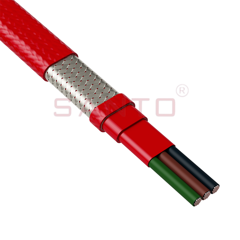
The stranded high temperature conductor is nickel plated to ensure a long life at elevated temperatures in corrosive environments. It is electrically isolated using an innovative sandwich construction...
See Details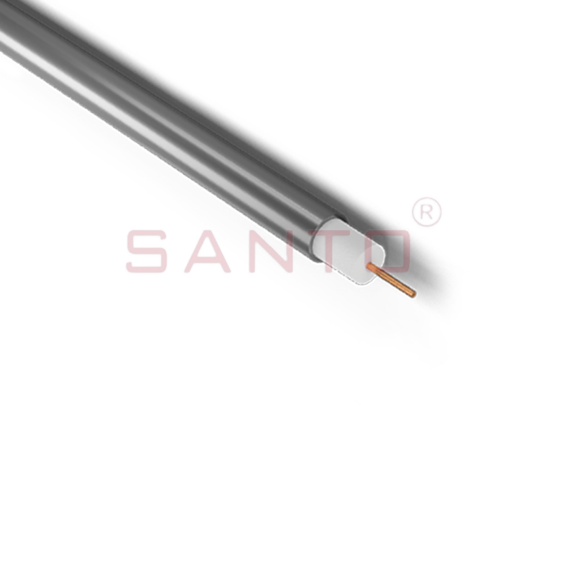
SANTO HAx mineral insulated (MI) Alloy 825 series heating cables are suitable for use in hazardous areas. They have been designed for use in freeze protection and temperature maintenance applications ...
See Details
Santo electric heating strips are widely used in key industries in China.

