 English
  English
 русский
 日本語
日本語 Español
 中文简体
中文简体
The SANTO UFA range of self-regulating heating cables is mainly used for frost protection of pipes and vessels but can also be used to maintain processes up to 65°C. These heating cables are available...
See Details
Content
Industrial heating and heat-tracing systems must perform reliably under demanding conditions. Pipelines, tanks, vessels, process lines, valves, instruments, and other equipment may require protection against freezing, viscosity loss, condensation, solidification, or unwanted temperature reduction. In many installations, the heating cable must also withstand corrosive chemicals, mechanical stress, moisture, elevated temperatures, and potentially explosive atmospheres.
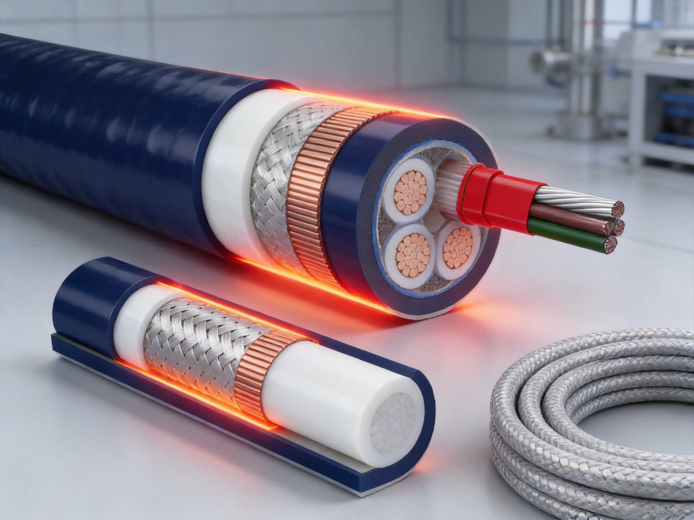
The XPI-3 is a polymer-insulated, series-resistance heating cable designed for industrial heat-tracing applications where durability, chemical resistance, controlled electrical performance, and high-temperature capability are essential. It uses a stranded nickel-plated high-temperature conductor, multiple layers of selected fluoropolymer insulation, a nickel-plated copper braid, and a final PTFE jacket. This construction provides electrical insulation, mechanical protection, an earth path, and resistance to many aggressive operating environments.
Unlike self-regulating heating cables, which change their heat output according to the surrounding temperature, the XPI-3 belongs to the series constant-power heating cable family. Its resistance is selected according to the required circuit length, voltage, power output, and installation conditions. This makes it suitable for long, carefully engineered circuits and for applications requiring predictable heat distribution over a defined heating zone.
The product family includes a wide range of resistance values, outside diameters, and electrical characteristics. The range extends from low-resistance cables intended for higher-current applications to high-resistance cables intended for longer circuits or lower-current operation. With correct design, installation, control, grounding, and protection, the XPI-3 can support demanding process-heating and heat-maintenance requirements.
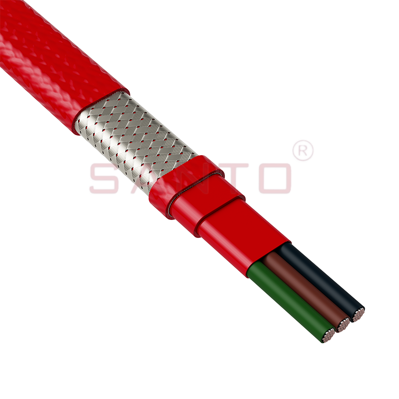
XPI-3
The central heating element is a stranded conductor manufactured for high-temperature operation. Nickel plating helps protect the conductor against oxidation and corrosion, particularly when the cable is exposed to elevated temperatures or corrosive surroundings. The stranded format also improves flexibility compared with a solid conductor of equivalent cross-sectional area.
Conductor stability is important in a series heating cable because the resistance of the heating element directly influences the heat output. A stable conductor helps the designer calculate circuit performance more accurately and supports consistent operation over the service life of the installation. The nickel-plated surface also contributes to long-term electrical reliability at temperatures where ordinary unplated conductive materials may deteriorate more quickly.
The conductor is electrically isolated by an innovative sandwich construction using selected high-temperature fluoropolymers. Rather than relying on a single basic insulation layer, the construction provides a multilayer barrier around the heating conductor. This design helps separate the energized conductor from the metallic braid and outer environment while maintaining performance under thermal and chemical stress.
Fluoropolymers are valued in industrial cable construction because they generally provide strong resistance to moisture, oils, solvents, acids, alkalis, and other aggressive substances. The exact suitability of the cable must always be verified against the chemical concentration, temperature, exposure time, and mechanical conditions of the intended application. Nevertheless, the polymer insulation system gives the XPI-3 an important advantage over many conventional heating cables using less chemically resistant insulation materials.
A braid made from nickel-plated copper strands surrounds the insulated heating conductor. This braid performs several functions. First, it improves mechanical protection against abrasion and handling damage. Second, it provides a low-ohmic resistance earth path when correctly connected to the protective earthing system. Third, it contributes to the overall cable structure and helps protect the internal insulation during installation.
The use of nickel-plated copper is particularly relevant in high-temperature environments. Bare copper may be vulnerable to oxidation or surface degradation when exposed to heat and aggressive atmospheres. Nickel plating offers an additional protective barrier while preserving the electrical conductivity and flexibility associated with copper.
The outer jacket is made from PTFE. This final layer provides the cable with a strong level of chemical resistance and temperature withstand capability. It protects the internal insulation and braid from the external environment and forms the primary surface exposed to process conditions, installation contact, moisture, and contaminants.
PTFE is widely used in demanding industrial applications because of its low reactivity and resistance to a broad range of chemicals. It also maintains useful properties across a wide temperature range. The final jacket is therefore an important part of the XPI-3 design rather than a simple protective covering. The complete conductor, insulation, braid, and jacket system is engineered to function as one integrated heating cable.
The XPI-3 series is intended for applications requiring stable and engineered resistance heating. The main technical characteristics supplied for the product include the following:
| Characteristic | Specification |
| Heating cable type | Series constant-power heating cable |
| Conductor | Stranded nickel-plated high-temperature conductor |
| Insulation | Multilayer selected high-temperature fluoropolymers |
| Protective braid | Nickel-plated copper braid with a low-ohmic resistance earth path |
| Outer jacket | PTFE |
| Maximum continuous exposure temperature | 260°C |
| Maximum intermittent exposure temperature | 300°C for up to 1,000 hours |
| Minimum installation temperature | -70°C |
| Maximum standard power output | 30 W/m, depending on the application |
| Rated voltage | Up to 450/750 VAC, U0/U |
| Minimum impact resistance | 4 joules according to the stated EN 50019 requirement |
| Minimum spacing between heating lines | 20 mm |
These values should be treated as design parameters rather than as permission to operate every cable at every listed limit simultaneously. Actual performance depends on the selected resistance, installation method, thermal insulation, ambient temperature, control strategy, circuit length, voltage, surrounding material, and operating duty. A qualified designer should confirm the complete system calculation before production or installation.
Many heating cables are suitable for ordinary freeze protection but become unsuitable when process temperatures rise significantly. The XPI-3 is designed for more demanding thermal conditions. Its high-temperature conductor, fluoropolymer insulation, nickel-plated braid, and PTFE jacket provide a coordinated construction for elevated-temperature service.
For continuous exposure, the stated maximum temperature is 260°C. For intermittent exposure, the cable can withstand up to 300°C for a stated period of up to 1,000 hours. This capability is useful in industrial equipment that experiences temporary temperature peaks during process cycles, startup, shutdown, cleaning, or controlled heating operations.
High-temperature resistance also supports applications where the heating cable is installed beneath thick thermal insulation surrounding a hot pipe or vessel. In these situations, the external surface of the cable may experience temperatures much higher than those found in ordinary building or domestic installations. The polymer system must remain electrically stable and mechanically sound throughout the expected duty cycle.
Temperature control remains essential. The cable should not be selected solely by its maximum exposure temperature. The maximum sheath temperature, process temperature, heat loss, control sensor location, thermal insulation performance, and possible abnormal conditions must be evaluated together. Temperature limiters or independent over-temperature protection may be necessary, particularly in hazardous areas or where the heated material can degrade, ignite, or undergo an unwanted reaction.
Industrial heat tracing is frequently installed in environments containing organic substances, corrosive chemicals, oils, solvents, gases, dust, moisture, or process residues. Such conditions can attack cable jackets, weaken insulation, corrode metallic components, or increase the risk of electrical leakage. The XPI-3 is constructed with fluoropolymers and PTFE to provide a high level of resistance against many organic and corrosive substances.
The chemical resistance of the outer jacket helps preserve the cable’s physical integrity. The multilayer insulation protects the energized conductor from external contamination, while the metallic braid provides an additional protective and grounding layer. This combination is especially valuable when the cable is installed on chemical processing equipment, storage tanks, transfer lines, or industrial piping.
However, chemical compatibility must be confirmed for each project. Chemical resistance is affected by temperature, concentration, pressure, mechanical loading, ultraviolet exposure, and the duration of contact. A material that performs well at room temperature may behave differently at an elevated process temperature. Project engineers should therefore provide the cable manufacturer with the chemical name, concentration, operating temperature, exposure conditions, and cleaning procedure before final selection.
The supplied application information identifies the cable for use in regional levels associated with Zone 1 and Zone 2 gas atmospheres and Zone 21 and Zone 22 dust atmospheres, as well as normal areas. These classifications indicate environments in which flammable gas, vapor, mist, or combustible dust may be present under defined operating conditions.
Use in a hazardous area requires more than selecting a suitable cable. The complete heating system must be evaluated, including the cable, cold leads, junction boxes, glands, controllers, sensors, terminations, protective devices, earthing conductors, and installation supports. The system must be installed in accordance with the applicable hazardous-area rules and the requirements of the project authority having jurisdiction.
Maximum surface temperature is a critical consideration. The cable must be controlled so that its surface temperature remains below the ignition temperature or temperature class required for the area and process. Appropriate temperature limiters, independent monitoring, and fault protection should be used where required by the design.
The XPI-3’s metallic braid provides a low-resistance earth path when correctly terminated. This supports fault-current conduction and helps protective devices respond to insulation faults. The protective braid does not eliminate the need for correct earthing, equipotential bonding, insulation testing, residual-current protection, and appropriate installation practices.
In a series heating cable, the heating conductor forms part of a complete electrical circuit. The resistance per unit length and total installed length determine the overall circuit resistance. The power output is related to the applied voltage and total resistance. Consequently, the cable must be selected and cut according to a defined electrical design rather than treated as an arbitrary cut-to-length product.
This arrangement differs from parallel constant-wattage cables, which commonly contain repeated heating zones or parallel paths. It also differs from self-regulating cables, whose power output changes as the surrounding temperature changes. Series cable technology can provide a simple, continuous heating path with predictable electrical characteristics when designed correctly.
One advantage is the availability of a broad resistance range. The XPI series includes models from 0.8 ohm/km to 8,000 ohm/km. This allows engineers to match circuit characteristics to different voltage levels, lengths, current limitations, and heat-loss requirements.
Another advantage is the relatively compact outside diameter. The listed nominal diameters range from approximately 4.1 mm to 11.9 mm, depending on the selected model. A compact cable can simplify installation on small-diameter pipework, valves, flanges, instruments, and irregular surfaces.
Series construction can also support long continuous heating circuits. The practical maximum length depends on resistance, supply voltage, power output, allowable current, environmental conditions, and maximum roll weight. The product information specifies a maximum roll weight of 120 kg and indicates that individual sections may be supplied up to 1,000 meters, subject to the selected resistance model and availability.
Compared with basic PVC-insulated or low-temperature heating products, the XPI-3 offers a more specialized construction for high-temperature and chemically aggressive service. Compared with some larger mineral-insulated cables, its polymer construction can provide easier handling and installation flexibility, subject to the project’s temperature, mechanical, and regulatory requirements.
The XPI range includes many standard models. The resistance value in the order number generally corresponds to the nominal resistance per kilometer at 20°C. For example, XPI-7 has a standard resistance of 7.0 ohm/km, while XPI-1.8 has a standard resistance of 1.8 ohm/km. Higher-resistance versions can be useful for longer circuits or lower-current designs, while lower-resistance versions can support higher-current applications with suitable power supplies and protection.
| Model | Resistance at 20°C, ohm/km | Temperature coefficient, x 10-3/K | Nominal outside diameter, mm | Approximate weight, kg/km |
| XPI-0.8 | 0.8 | 4.3 | 11.9 | 404 |
| XPI-1.8 | 1.8 | 4.3 | 8.6 | 208 |
| XPI-2.9 | 2.9 | 4.3 | 6.9 | 143 |
| XPI-7 | 7.0 | 4.3 | 5.5 | 83 |
| XPI-15 | 15.0 | 4.3 | 5.1 | 61 |
| XPI-50 | 50 | 1.3 | 4.9 | 57 |
| XPI-100 | 100 | 0.4 | 5.2 | 67 |
| XPI-200 | 200 | 0.40 | 4.8 | 53 |
| XPI-600 | 600 | 0.18 | 4.5 | 48 |
| XPI-1,000 | 1,000 | 0.04 | 4.5 | 48 |
| XPI-2,000 | 2,000 | 0.35 | 4.6 | 49 |
| XPI-4,000 | 4,000 | 0.35 | 4.2 | 42 |
| XPI-8,000 | 8,000 | 0.10 | 4.1 | 40 |
The complete product range contains additional resistance values, including XPI-11.7, XPI-17.8, XPI-25, XPI-31.5, XPI-65, XPI-80, XPI-150, XPI-180, XPI-320, XPI-380, XPI-480, XPI-700, XPI-810, XPI-1,440, XPI-1,750, XPI-3,000, XPI-4,400, XPI-5,160, XPI-5,600, and XPI-7,000.
The stated resistance tolerance is plus 10 percent and minus 5 percent. For models below 31.5 ohm/km, the resistance of the conductive material changes with temperature and must be considered during design. This is important because conductor resistance at operating temperature may differ from the nominal value measured at 20°C.
A heating cable system requires suitable cold-end connections to connect the heating section to the power supply. The recommended cold-end wire models are matched to the XPI family and include options based on standard cross-sectional area, current capacity, outside diameter, resistance, and temperature coefficient.
| Cross-sectional area, mm² | Approximate current rating, A | Outside diameter, mm | Resistance at 20°C, ohm/km | Matching model |
| 2.5 | 32 | 5.5 | 7.0 | XPI-7 |
| 4 | 42 | 6.1 | 4.4 | XPI-4.4 |
| 6 | 54 | 6.9 | 2.9 | XPI-2.9 |
| 10 | 73 | 8.6 | 1.8 | XPI-1.8 |
| 16 | 98 | 10.1 | 1.1 | XPI-1.1 |
| 25 | 129 | 11.9 | 0.8 | XPI-0.8 |
The XPI-S cold-end wire may be used as an alternative where appropriate. Connection design should account for the maximum conductor temperature, current, insulation compatibility, environmental exposure, termination method, and hazardous-area requirements. Cold ends should not be treated as ordinary extension cables unless their electrical and thermal performance has been verified for the installation.
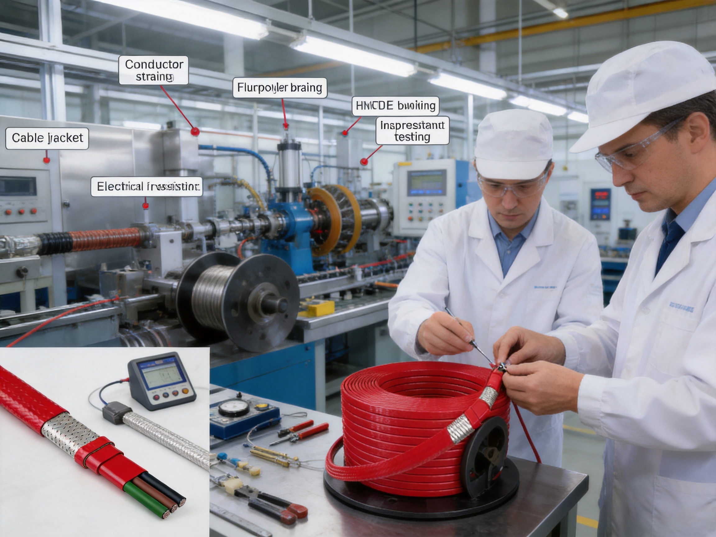
Reliable heating cable production begins with controlled material preparation. Conductive strands, nickel plating, fluoropolymer insulation materials, copper braid wire, and PTFE jacket materials must be selected according to the required electrical, thermal, mechanical, and chemical performance. Material traceability is important because small changes in conductor composition, plating quality, insulation thickness, or polymer processing can affect final cable performance.
The manufacturer’s experience in electric heating products supports the integration of material selection, cable design, production, testing, and application guidance. Santo Thermal Control Technology Co., Ltd. reports more than 35 years of industry experience and a product portfolio covering constant-power heating cables, self-regulating heating cables, silicone rubber heaters, glass-fiber heating products, mineral-insulated cables, snow-melting cables, and accessories.
Stranding is carried out to create a flexible and electrically consistent conductor. The conductor must maintain its geometry during insulation, braiding, winding, and installation. Nickel plating is applied to help protect the conductive strands from high-temperature oxidation and corrosive exposure.
Quality control at this stage may include dimensional inspection, plating verification, resistance testing, visual checks, and continuity testing. Consistent conductor resistance is particularly important for series heating cables because the final heating performance depends directly on the resistance per unit length.
The selected fluoropolymer insulation layers are applied around the conductor using controlled extrusion processes. The sandwich construction must maintain concentricity, wall thickness, adhesion or layer integrity where required, and freedom from pinholes or other defects. Processing temperatures and line speeds must be controlled to preserve the properties of the polymer materials.
Insulation quality can be evaluated through high-voltage withstand tests, insulation resistance tests, dimensional inspection, spark testing, and visual examination. These controls help identify defects before the cable proceeds to braiding and jacket application.
The nickel-plated copper braid is applied over the insulated core with controlled coverage and tension. Braid quality affects mechanical strength, earthing performance, flexibility, and the protection provided to the insulation. The final PTFE jacket is then applied to form the external surface of the cable.
The jacket process must be controlled to achieve a stable outside diameter and consistent coverage. The finished cable may be inspected for surface damage, dimensional conformity, resistance, insulation integrity, braid continuity, and labeling. These production steps support the dependable performance expected from industrial heat-tracing products.
Santo Thermal Control Technology Co., Ltd. states that it operates research, design, production, and manufacturing activities for automatic temperature-control heating products and related electric heating systems. The company also reports cooperation in product research with Harvard University in the United States, a product simulation testing laboratory, and continued investment in new product development.
The company reports ISO9001 quality management system certification and national CCC certification for its products. It also states that selected products have obtained explosion-proof certification and EAC Eurasian Union certification. Certification applicability depends on the exact product, configuration, market, and installation method, so the relevant certificate should be requested and reviewed for each project.
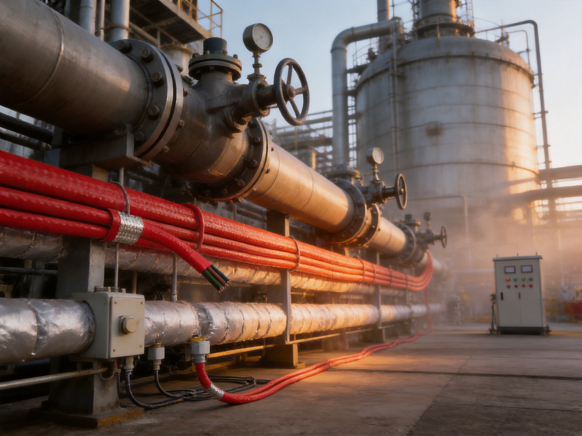
The XPI-3 can be considered for pipelines exposed to low ambient temperatures where freezing would interrupt operation or damage equipment. The cable may be installed along the pipe and covered with suitable thermal insulation. A temperature sensor and controller can regulate the system to maintain the required minimum process temperature.
For outdoor piping, the design should account for wind, rain, snow, solar exposure, insulation wetting, supports, valves, flanges, and thermal bridges. The heating cable must be secured without damaging the jacket, and the complete assembly must be protected from mechanical impact during installation and maintenance.
Some liquids become more viscous as their temperature falls. This can increase pumping energy, reduce flow, or make transfer operations difficult. Heat tracing can help maintain a target temperature and support reliable movement through pipelines, pumps, filters, valves, and loading systems.
Because the XPI-3 is available in many resistance values, engineers can match the heating circuit to the length and heat-loss profile of the process line. Temperature control should prevent overheating of the liquid, especially when the material has a narrow allowable temperature range or may decompose at excessive temperatures.
Storage tanks and process vessels may need heating to prevent solidification, maintain viscosity, or support a production process. The cable can be installed on suitable external surfaces, provided that the surface temperature, spacing, mechanical support, and insulation arrangement are properly designed.
Tank heating requires particular attention to thermal expansion, access points, agitators, nozzles, supports, ladders, and inspection openings. The cable should not be installed where it may be crushed, sharply bent, immersed in incompatible substances, or exposed to unplanned mechanical loading.
Valves, flanges, strainers, pumps, and instruments often create localized heat-loss points. A properly engineered heating system can provide additional heat in these areas while maintaining the overall process temperature. Small cable diameters can simplify routing around irregular components, but the minimum bend radius and minimum spacing must be respected.
Although the XPI-3 is primarily an industrial high-temperature series heating cable, appropriately selected heating cables can also be used in specialized snow and ice prevention systems where the electrical and environmental design is suitable. Surface heating applications require careful spacing, waterproofing, ground-fault protection, and control. The 20 mm minimum spacing specified for the product should be treated as a minimum installation requirement unless a project-specific design provides otherwise.
The minimum installation temperature is stated as -70°C. Even with this low-temperature capability, the cable should be handled carefully in cold conditions because polymer flexibility may change as temperature falls. The cable should be uncoiled without twisting, kinking, crushing, or dragging it across sharp edges.
The stated minimum bending radius at 70°C is based on cable diameter. When the heating wire diameter is less than 6 mm, the minimum bending radius is 25 times the cable diameter. When the diameter is greater than 6 mm, the minimum bending radius is 6 times the cable diameter. These limits must be observed during routing, termination, storage, and installation.
The cable should be placed in close thermal contact with the heated surface where practical. Poor contact can create hot spots, reduce heat transfer, and increase the surface temperature of the cable. Suitable attachment methods should hold the cable securely without cutting into or compressing the PTFE jacket.
Heating lines must be installed with a minimum spacing of 20 mm. Parallel runs should not be allowed to cross or touch unless the system design and manufacturer instructions specifically permit it. The cable should be positioned to avoid sharp corners, moving parts, drain points, areas of frequent impact, and locations where maintenance activity could damage it.
Thermal insulation is an essential part of the system. Without suitable insulation, heat loss may be too high for the selected cable, and the system may consume more energy than expected. Insulation should be dry, continuous, and properly sealed against water ingress. Cladding should protect the insulation and cable from weather, chemicals, and mechanical damage.
After installation, the cable should be tested before insulation is applied and again after the installation is complete. Typical checks include conductor resistance, insulation resistance, braid continuity, earth continuity, visual condition, and high-voltage withstand where required by the project procedure. Test results should be recorded as part of the commissioning documentation.
The manufacturer recommends the use of a 30 mA leakage protection device for maximum safety and fire prevention. Where the design may produce a high leakage current, a leakage protection device up to 300 mA may be necessary, subject to the applicable electrical code, equipment requirements, and safety assessment.
Residual-current protection does not replace correct insulation, grounding, circuit protection, or temperature control. The braid must be properly connected to the protective earth system. Circuit breakers or fuses must be selected according to the calculated operating current, inrush conditions where applicable, fault levels, and cable capacity.
Temperature control should be selected according to the process requirement. A thermostat may be adequate for simple freeze protection, while a process installation may require a sensor, controller, independent high-temperature limiter, alarm system, and shutdown interlock. In hazardous areas, the control system should be compatible with the area classification and the required protection method.
Designers must consider the temperature coefficient of resistance. At operating temperatures above 20°C, resistance may change from the nominal catalog value. This affects current and power calculations, particularly for lower-resistance models. The cable length, supply voltage, total resistance, maximum current, heat output, and operating temperature should be calculated together.
Industrial customers often need a heating cable configured for a specific pipe length, voltage, heat loss, hazardous-area classification, or connection arrangement. A broad standard resistance range gives the manufacturer a useful foundation for custom engineering. Standard models can reduce development time while still allowing the system to be matched to project requirements.
Santo describes itself as an OEM and ODM heating cable manufacturer with export experience and a wide distributor network. Its product range covers several heating technologies, allowing customers to source complete or complementary solutions from one technical supplier. This can simplify product selection, documentation, accessories, and after-sales communication.
Custom projects may involve cable length, cold-end selection, termination, reel configuration, labeling, packaging, operating voltage, power density, control components, or installation accessories. Any custom design should be validated through electrical, thermal, mechanical, chemical, and safety assessments before entering production.
Self-regulating cable is convenient for many freeze-protection applications because its output decreases as the surrounding temperature rises. However, self-regulating products may have limitations in high-temperature exposure, maximum circuit length, startup current, or chemical resistance depending on their construction.
The XPI-3 provides a deliberately selected series resistance and can be specified for a wide range of circuit lengths and power requirements. It is therefore attractive when predictable resistance, high-temperature polymer insulation, and chemical durability are more important than automatic self-regulation.
Parallel constant-wattage cables may be cut to specified lengths and can be convenient for modular installations. The XPI-3, by contrast, is selected as a series circuit whose total resistance must match the required design. This may require more engineering discipline, but it also enables a broad resistance range and continuous heating path.
Mineral-insulated cables can offer excellent high-temperature capability and mechanical strength. They may also be more rigid, more difficult to terminate, and more demanding to install. The XPI-3 offers a polymer-insulated alternative with a compact structure, flexible handling, chemical resistance, and a metallic protective braid.
The best choice depends on the project. Extremely high temperatures, severe mechanical loading, direct immersion, radiation, or unusual chemical exposure may require another cable construction. The XPI-3 is particularly well suited to applications where high-temperature polymer performance, flexibility, series resistance, and chemical resistance must be combined.
A properly designed and installed XPI-3 system can provide long-term service, but maintenance remains important. Periodic inspections should check the outer jacket, thermal insulation, protective cladding, junction boxes, glands, terminations, controllers, and exposed sections of cable.
Insulation resistance testing can identify moisture ingress, mechanical damage, contamination, or aging. Resistance measurements can help detect conductor damage or connection problems. Test results should be compared with commissioning records to identify gradual changes over time.
Maintenance personnel should avoid drilling, welding, cutting, or fastening through heated surfaces without confirming the location of the cable. Equipment modifications can unintentionally damage the heating circuit. Before maintenance work begins, the system should be isolated, locked out, and verified as de-energized.
Damaged heating cable should not be repaired using improvised joints or ordinary electrical tape. Repairs must use approved components and methods suitable for the cable construction, operating temperature, chemical environment, and hazardous-area classification. In some situations, replacement of the affected section may be safer than field repair.
The XPI-3 is a polymer-insulated series constant-power heating cable. It uses a nickel-plated stranded conductor, multilayer high-temperature fluoropolymer insulation, a nickel-plated copper braid, and a PTFE outer jacket.
The stated maximum continuous exposure temperature is 260°C. The stated maximum intermittent exposure temperature is 300°C for up to 1,000 hours. Actual operating limits must be confirmed for the complete heating system and control arrangement.
Yes, the fluoropolymer insulation and PTFE jacket are designed to provide resistance to organic and corrosive substances. Chemical compatibility should be verified using the actual chemical, concentration, temperature, and exposure conditions.
No. It is a series constant-power heating cable. Its resistance and installed length are selected during system design, and its output depends on the electrical and thermal conditions of the circuit.
Series heating cables should not be cut or configured arbitrarily. The final length must match the resistance, supply voltage, current, and power requirements of the design. Cutting, joining, and terminating should follow the manufacturer’s instructions.
The nickel-plated copper braid provides additional mechanical protection and a low-ohmic resistance earth path when properly connected. It must be included in the grounding and safety design.
The stated minimum spacing is 20 mm between heating lines. Project-specific installation instructions may require greater spacing depending on power density, surface temperature, and application conditions.
At 70°C, the minimum bending radius is 25 times the cable diameter when the heating wire diameter is below 6 mm, and 6 times the cable diameter when the diameter is above 6 mm.
The product information identifies applications associated with Zone 1 and Zone 2 gas atmospheres and Zone 21 and Zone 22 dust atmospheres. The complete system must be approved, designed, installed, and controlled according to the applicable hazardous-area requirements.
Yes. Reliable temperature control and, where necessary, independent temperature limiters are required to prevent excessive surface or process temperatures. The correct control method depends on the application and hazard assessment.
The supplied product information recommends a 30 mA leakage protection device for maximum safety. Where high leakage current may occur, a device up to 300 mA may be necessary, subject to the applicable design and safety requirements.
Important information includes the heated surface, pipe or vessel dimensions, required maintenance temperature, minimum ambient temperature, process temperature, thermal insulation, heat-loss estimate, supply voltage, circuit length, hazardous-area classification, chemical exposure, control method, and installation conditions.
Heating cable reliability depends on more than the raw materials used in the product. It also depends on conductor control, insulation consistency, braid coverage, jacket quality, electrical testing, documentation, engineering support, and the manufacturer’s ability to understand the complete application.
Santo Thermal Control Technology Co., Ltd. combines product development, manufacturing, testing, sales, and application support. The company reports more than 35 years of industry experience, an annual output exceeding 10,000 units or product sets, more than 2,000 distributors, and business activity in more than 85 areas. It also reports a history of developing heating products for petroleum, chemical, gas, construction, solar energy, geothermal cultivation, antifreeze, deicing, heat tracing, and insulation applications.
This breadth of experience can be valuable for OEM customers, engineering contractors, distributors, and industrial end users. A supplier familiar with multiple heating technologies can help determine whether a series constant-power cable, self-regulating cable, silicone rubber heater, glass-fiber cable, mineral-insulated cable, or another product is most appropriate.
For the XPI-3, the combination of high-temperature polymer insulation, nickel-plated conductive materials, protective braid, PTFE jacketing, broad resistance selection, and application-oriented engineering makes the product a strong option for demanding heat-tracing projects.
The XPI-3 is engineered for industrial heating applications where ordinary low-temperature cables may not provide sufficient thermal, chemical, or mechanical performance. Its stranded nickel-plated high-temperature conductor supports long-term electrical stability. The multilayer fluoropolymer insulation provides a robust electrical barrier. The nickel-plated copper braid adds mechanical protection and a low-resistance earth path, while the PTFE jacket provides a durable external layer with strong chemical and temperature resistance.
The product’s broad resistance range allows engineers to configure circuits for different lengths, voltages, current levels, and heat requirements. Its compact diameter and flexible polymer construction can simplify installation on pipes, tanks, vessels, valves, flanges, and process equipment. The stated temperature capability of 260°C continuous and 300°C intermittent further expands its suitability for high-temperature industrial service.
Successful use depends on proper engineering. Resistance variation with temperature, minimum bending radius, minimum line spacing, thermal insulation, temperature control, grounding, leakage protection, hazardous-area certification, and chemical compatibility must all be reviewed. When these requirements are addressed, the XPI-3 can provide a dependable and durable solution for freeze protection, process temperature maintenance, viscosity control, antifreeze heating, and specialized industrial heat tracing.
1. XPI Product Specification, technical product information supplied for the XPI polymer-insulated series heating cable family.
2. XPI Constant Watt Technology, application and design information supplied for series constant-power heating systems.
3. XPI Heating Systems, installation, control, and system application information supplied for industrial heat tracing.
4. XPI Product Description, construction and technical data for the nickel-plated conductor, fluoropolymer insulation, copper braid, and PTFE jacket.
5. EN 50019, electrical equipment protection and impact-resistance requirements referenced in the supplied product data.
6. ISO 9001, quality management system principles relevant to controlled heating cable manufacturing.
7. Industrial Heat Tracing Design Practice, general principles for cable selection, thermal calculation, control, grounding, inspection, and maintenance.
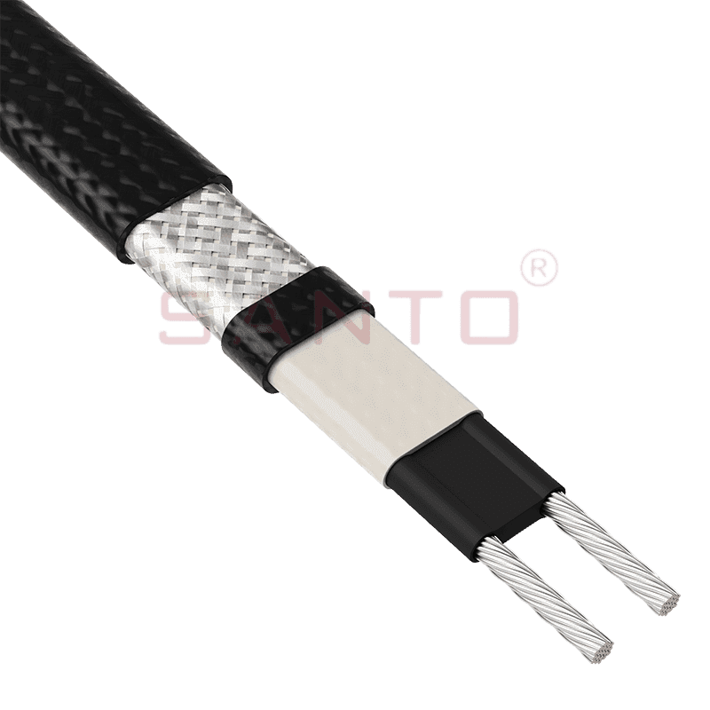
The SANTO UFA range of self-regulating heating cables is mainly used for frost protection of pipes and vessels but can also be used to maintain processes up to 65°C. These heating cables are available...
See Details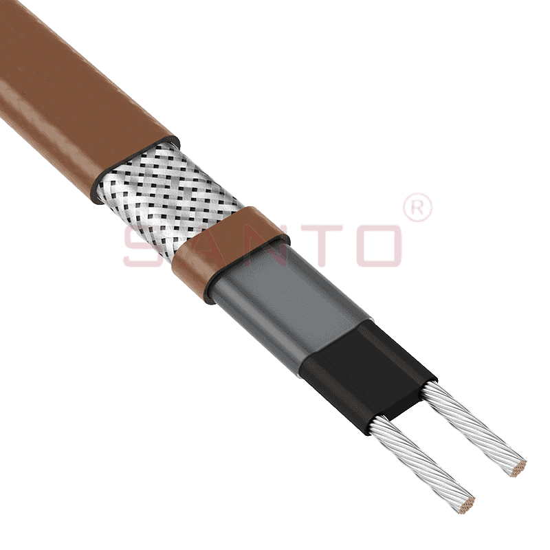
The SANTO UFB range of self-regulating heating cables is mainly used for frost protection of pipes and vessels requiring a higher power output than the UFA heating cables can supply. They can also be ...
See Details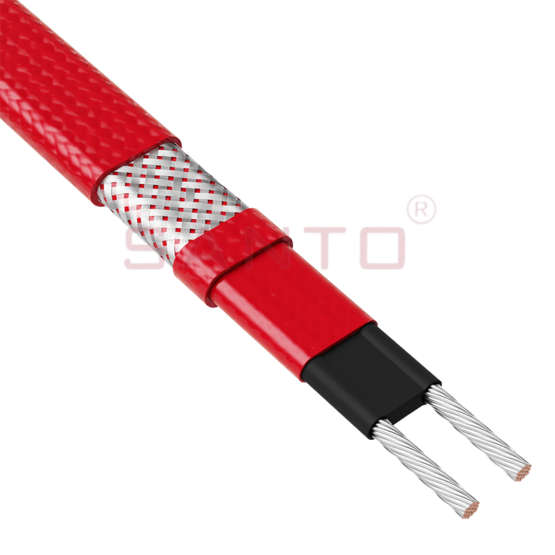
The SANTO UFC range of self-regulating heating cables is used for frost protection of pipes and vessels that require steam cleaning. They can also be used to maintain processes up to 121°C. These heat...
See Details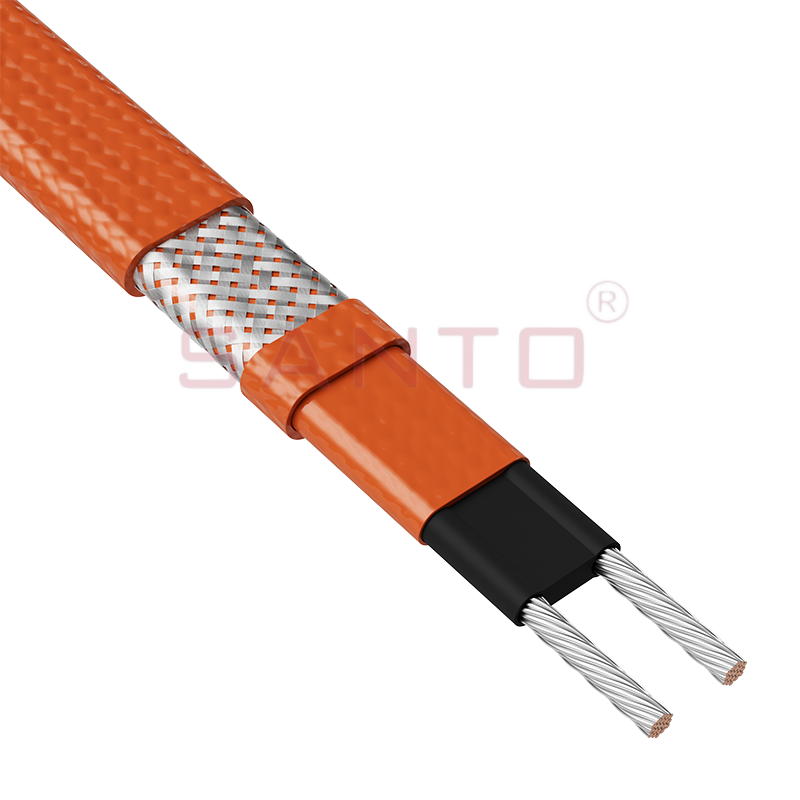
The SANTO UFO range of self-regulating heating cables is mainly used for frost protection of pipes and vessels that require steam cleaning . They can also be used to maintain processes up to 150°C. Th...
See Details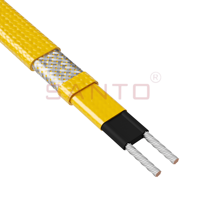
The SANTO UFD series of self-regulating heating cables are mainly used for freeze protection of pipes and vessels, but can also be used to maintain processes up to 200°C. These heating cables are avai...
See Details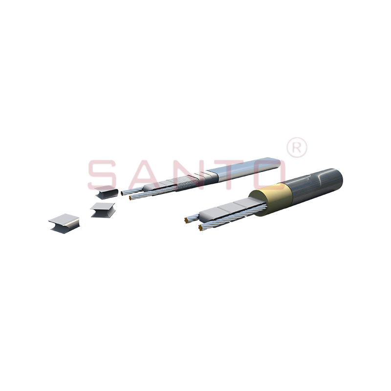
SANTO UFY heating wire is suitable for applications that maintain process temperatures up to 260 ℃ and can be steam blown; The self-regulating and parallel circuit heating wires of the UFY series are ...
See Details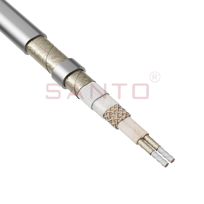
The SANTO UFM series self-regulating heating cables are mainly used for freeze protection of pipes and vessels, but can also be used to maintain processes up to 400°C. These heating cables are availab...
See Details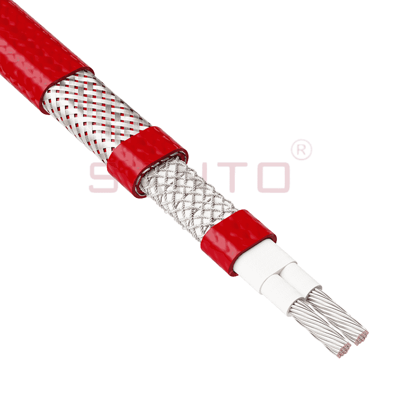
The SANTO ACC range of power-limiting heating cables is mainly used for temperature maintenance of processes and offers the advantage of a high power output at high temperatures which can reduce the n...
See Details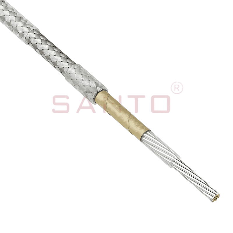
The stranded high temperature conductor is nickel plated to ensure a long life at elevated temperatures in corrosive environments. It is electrically isolated using an innovative sandwich construction...
See Details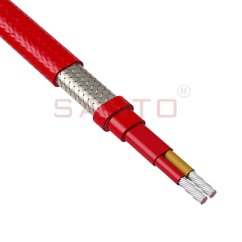
The stranded high temperature conductor is nickel plated to ensure a long life at elevated temperatures in corrosive environments. It is electrically isolated using an innovative sandwich construction...
See Details
The stranded high temperature conductor is nickel plated to ensure a long life at elevated temperatures in corrosive environments. It is electrically isolated using an innovative sandwich construction...
See Details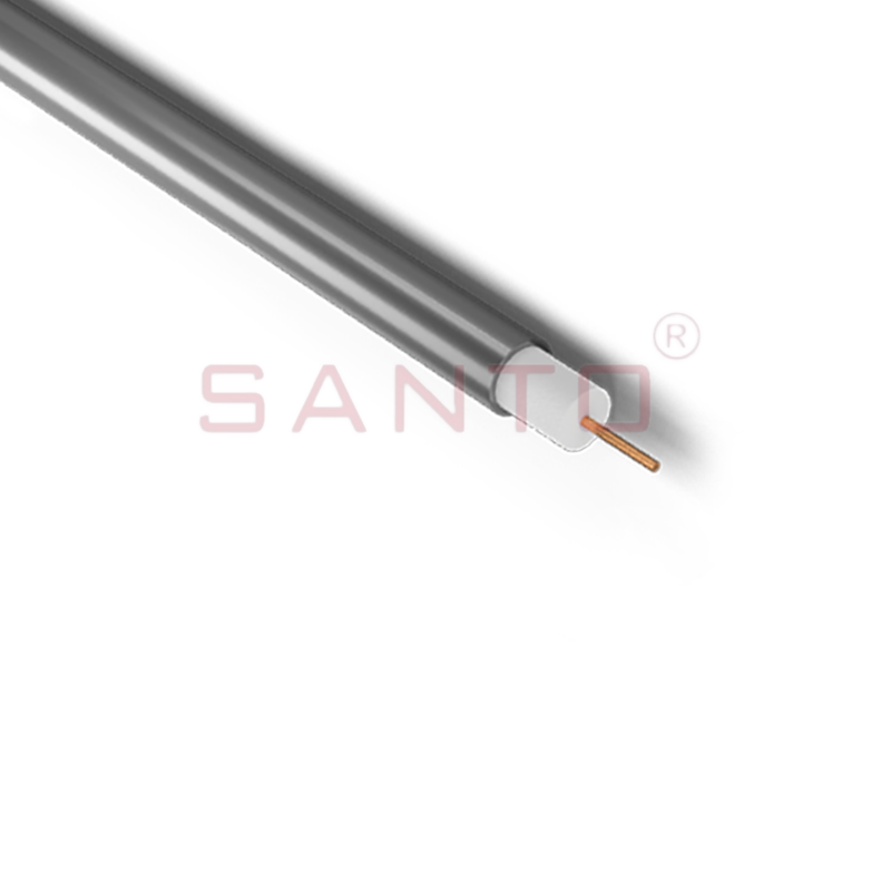
SANTO HAx mineral insulated (MI) Alloy 825 series heating cables are suitable for use in hazardous areas. They have been designed for use in freeze protection and temperature maintenance applications ...
See Details
Santo electric heating strips are widely used in key industries in China.

