 English
  English
 русский
 日本語
日本語 Español
 中文简体
中文简体
The SANTO UFA range of self-regulating heating cables is mainly used for frost protection of pipes and vessels but can also be used to maintain processes up to 65°C. These heating cables are available...
See Details
Industrial heating and heat-tracing systems must perform reliably under demanding conditions. Pipelines, tanks, valves, process equipment, vessels, loading systems, and outdoor structures may be exposed to freezing temperatures, corrosive chemicals, moisture, mechanical stress, explosive atmospheres, and large temperature fluctuations. In these environments, an ordinary electrical cable is rarely sufficient. The heating cable must provide stable thermal output, strong electrical insulation, dependable grounding, chemical resistance, and long service life.
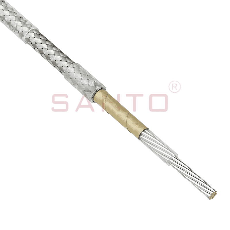
The XPI-1 is a series constant power heating cable designed for high-temperature industrial heat tracing. Its construction combines a stranded nickel-plated high-temperature conductor, selected fluoropolymer insulation, a nickel-plated copper braid, and a final PTFE jacket. This layered design provides a balanced solution for applications that require heating performance together with resistance to chemicals, elevated temperatures, mechanical damage, and electrically hazardous environments.
Unlike basic heating wires that rely on a simple resistance conductor and a single polymer covering, the XPI-1 uses a multi-layer construction engineered for industrial service. The conductor is protected from accelerated oxidation, the insulation system separates the energized core from the protective braid, and the braid provides both mechanical reinforcement and a low-resistance earth path. The outer PTFE jacket adds another barrier against aggressive organic and corrosive substances.
This article explains the construction, operating principles, technical capabilities, installation considerations, product range, manufacturing strengths, and application benefits of the XPI-1 series constant power heating cable supplied by Santo Thermal Control Technology Co., Ltd.
XPI-1
Content
The XPI-1 belongs to the series constant power heating cable category. A constant power heating cable is designed to produce a defined electrical heating output along its energized length, subject to the selected resistance, applied voltage, installation conditions, and operating temperature. This makes it suitable for engineered heat-tracing systems where the required heat loss and circuit length can be calculated in advance.
The cable uses a stranded high-temperature conductor. The conductor is nickel-plated to improve durability at elevated temperatures and in corrosive environments. Nickel plating helps protect the conductive material from oxidation and supports more stable performance where the cable is exposed to thermal cycling or chemically active surroundings.
The conductor is electrically isolated using a sandwich construction made from selected high-temperature fluoropolymers. This insulation arrangement creates a robust dielectric barrier around the heating element. Fluoropolymers are valued in industrial heating because they can maintain useful electrical and mechanical properties across a wide temperature range while resisting many chemicals.
A braid made from nickel-plated copper strands surrounds the insulated conductor. This braid has two important functions. First, it provides additional mechanical protection against abrasion and handling damage. Second, it creates a low-ohmic resistance earth path that can be connected to the protective earthing system of the installation.
The final external layer is a PTFE jacket. PTFE is known for its strong chemical resistance, low friction, and ability to withstand high temperatures. As the outside layer, it helps protect the inner cable construction from process chemicals, moisture, and environmental contamination.
The result is a heating cable with a carefully coordinated electrical, thermal, chemical, and mechanical structure. Each layer contributes to reliability, and the combined design is more suitable for harsh industrial environments than a basic single-insulated resistance wire.
The heating conductor is stranded rather than formed as a simple solid wire. Stranding can improve flexibility and reduce the likelihood of conductor fracture caused by repeated handling or controlled bending during installation. Although the cable still has a specified minimum bending radius and must not be bent arbitrarily, the stranded design supports practical field installation.
Nickel plating is especially important for high-temperature heating applications. At elevated temperatures, unprotected conductive materials may oxidize more rapidly, which can affect electrical resistance and long-term service life. In corrosive environments, plating also provides an additional protective interface between the conductor and the surrounding insulation system.
The conductor resistance is selected according to the model. The XPI range includes low-resistance versions for higher current capacity and high-resistance versions for longer heating circuits or different voltage and power requirements. Design engineers can select a resistance that corresponds to the required circuit length, operating voltage, power output, and control arrangement.
The insulation system uses a sandwich construction of selected high-temperature fluoropolymers. This is a significant feature because the insulation is not merely intended to prevent short circuits under normal conditions. It must also remain stable when exposed to heat, mechanical movement, chemicals, and long operating periods.
Fluoropolymer materials are widely used in severe industrial environments because they provide a combination of dielectric strength and chemical resistance. They are suitable for installations where ordinary thermoplastic materials may soften, degrade, or lose performance. The insulation also helps maintain separation between the heating conductor and the surrounding metallic braid.
The layered insulation approach supports the overall safety of the product. If the outer jacket is exposed to local wear or contamination, the insulation system remains a primary barrier around the energized conductor. Correct installation, testing, grounding, and temperature control are still essential, but the construction gives the system a strong foundation.
The nickel-plated copper braid provides a low-resistance protective earth path. This is important in industrial heat tracing because fault current must have a reliable route back to the protective device if the insulation system is damaged.
The braid also gives the cable increased resistance to mechanical damage. During installation, the cable may be pulled, positioned against pipe supports, fixed beneath insulation, or routed around fittings. The braid helps protect the inner insulation against abrasion and handling stress. It is not a substitute for correct installation practice, but it adds an important layer of physical protection.
Nickel plating on the copper braid improves its suitability for elevated-temperature service. It can help the braid retain its protective function when the cable is used in applications with continuous or intermittent high-temperature exposure.
The PTFE jacket is the outermost protective layer of the XPI-1. It is selected for its resistance to many organic and corrosive substances, as well as its ability to withstand high temperatures. In chemical processing, oil and gas, and other industrial facilities, the outer jacket may encounter vapors, splashes, cleaning agents, and process residues.
PTFE also has a low-friction surface, which can assist with routing and positioning during installation. However, the cable must still be handled according to the manufacturer’s instructions. Excessive pulling force, sharp bends, cuts, crushing, or direct contact with sharp edges can damage any cable construction.
The combination of fluoropolymer insulation and a PTFE jacket distinguishes the XPI-1 from many general-purpose heating cables. It is designed for applications in which thermal and chemical performance are equally important.
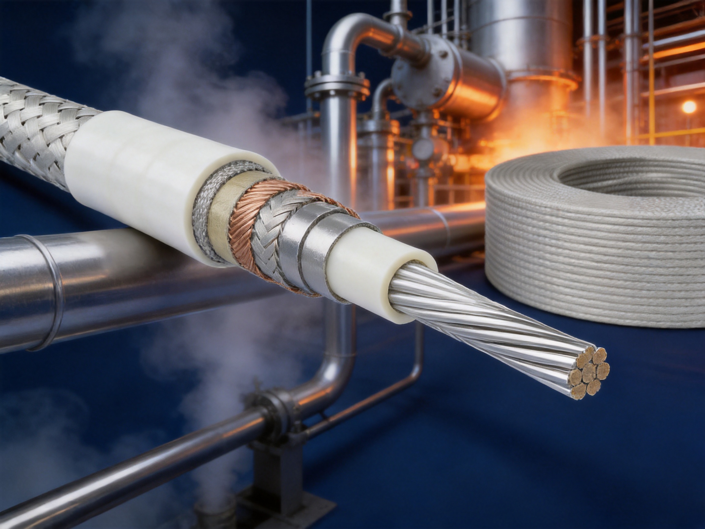
The XPI-1 series is designed for demanding temperature and environmental conditions. The stated maximum exposure temperature is 260°C for continuous operation and 300°C for intermittent operation for up to 1,000 hours. These values describe cable exposure capability and must not be interpreted as permission to operate every installation continuously at the maximum temperature.
The actual operating temperature depends on the pipe or equipment material, insulation system, ambient conditions, process temperature, circuit design, controller settings, heat dissipation, and the selected heating cable. A suitable temperature limiter or control system must be used to prevent overheating and to keep the application within its design limits.
The minimum installation temperature is specified as -70°C. This capability is useful for outdoor installations, cold climates, refrigerated areas, and construction work performed in low-temperature conditions. The cable should nevertheless be stored, uncoiled, and installed carefully in cold conditions because very low temperatures can affect the flexibility of polymer materials.
The maximum standard power output is 30 W/m, although the specific permitted output depends on the application. The required output should be calculated from heat-loss analysis rather than selected only from the cable’s maximum rating. Excessive output can cause overheating, while insufficient output may fail to maintain the required process or surface temperature.
The rated voltage is up to 450/750 VAC, expressed as U0/U. System voltage, circuit length, resistance, current, power, switching method, and protective device ratings must all be checked before installation.
The minimum impact resistance is listed as 4 joules according to the EN 50019 standard reference provided for the product. The cable must still be protected from foreseeable impact, crushing, and sharp mechanical hazards in the field.
A minimum spacing of 20 mm between heating lines is specified. This spacing helps reduce the risk of concentrated heat accumulation when multiple heating runs are installed on the same surface. The final spacing and layout should be determined by the application design, thermal calculations, equipment geometry, and applicable electrical safety requirements.
| Performance parameter | Stated XPI series value | Design significance |
|---|---|---|
| Maximum continuous exposure temperature | 260°C | Suitable for engineered high-temperature heat-tracing applications |
| Maximum intermittent exposure temperature | 300°C for up to 1,000 hours | Supports selected short-term or intermittent high-temperature conditions |
| Minimum installation temperature | -70°C | Allows installation in very cold environments when handled correctly |
| Maximum standard power output | 30 W/m | Provides a broad range for industrial heat-maintenance duties |
| Rated voltage | Up to 450/750 VAC | Supports engineered circuit designs within the applicable electrical limits |
| Minimum impact resistance | 4 joules | Provides a stated level of mechanical resistance under the referenced standard |
| Minimum heating-line spacing | 20 mm | Helps manage heat distribution in multiple-run installations |
The XPI series is available in a broad resistance range. The listed models extend from XPI-0.8 through XPI-8000, with standard resistance values expressed in ohms per kilometre at 20°C. This range allows the same general cable construction to be adapted to different electrical currents, heating lengths, power requirements, and installation designs.
Lower resistance cables generally allow higher current at a given voltage and can be used where the design calls for higher current capacity or shorter circuit configurations. Higher resistance cables can support different combinations of voltage, circuit length, and power per metre. The correct choice must be made using electrical calculations and the application’s thermal requirements.
Resistance is affected by temperature. The product information notes that for heat-tracing wire below 31.5 ohms per kilometre, the resistance of the conductive material is a function of temperature and must be considered during design. This is an important engineering point. A circuit designed only from its resistance at 20°C may not accurately represent its hot operating current or power.
The listed resistance tolerance is +10% and -5%. This tolerance should be included in circuit calculations, power supply selection, protective device coordination, and commissioning measurements. Before energization, the installed circuit should be tested and its measured resistance recorded.
| Representative model | Standard resistance at 20°C | Temperature coefficient | Approximate outside diameter | Approximate weight |
|---|---|---|---|---|
| XPI-0.8 | 0.8 ohm/km | 4.3 × 10⁻³/K | 11.9 mm | 404 kg/km |
| XPI-1.1 | 1.1 ohm/km | 4.3 × 10⁻³/K | 10.1 mm | 306 kg/km |
| XPI-1.8 | 1.8 ohm/km | 4.3 × 10⁻³/K | 8.6 mm | 208 kg/km |
| XPI-2.9 | 2.9 ohm/km | 4.3 × 10⁻³/K | 6.9 mm | 143 kg/km |
| XPI-4.4 | 4.4 ohm/km | 4.3 × 10⁻³/K | 6.1 mm | 112 kg/km |
| XPI-7 | 7.0 ohm/km | 4.3 × 10⁻³/K | 5.5 mm | 83 kg/km |
| XPI-11.7 | 11.7 ohm/km | 4.3 × 10⁻³/K | 5.2 mm | 65 kg/km |
| XPI-25 | 25.0 ohm/km | 3.0 × 10⁻³/K | 4.9 mm | 57 kg/km |
| XPI-50 | 50 ohm/km | 1.3 × 10⁻³/K | 4.9 mm | 57 kg/km |
| XPI-100 | 100 ohm/km | 0.4 × 10⁻³/K | 5.2 mm | 67 kg/km |
| XPI-200 | 200 ohm/km | 0.40 × 10⁻³/K | 4.8 mm | 53 kg/km |
| XPI-600 | 600 ohm/km | 0.18 × 10⁻³/K | 4.5 mm | 48 kg/km |
| XPI-1000 | 1,000 ohm/km | 0.04 × 10⁻³/K | 4.5 mm | 48 kg/km |
| XPI-2000 | 2,000 ohm/km | 0.35 × 10⁻³/K | 4.6 mm | 49 kg/km |
| XPI-4000 | 4,000 ohm/km | 0.35 × 10⁻³/K | 4.2 mm | 42 kg/km |
| XPI-8000 | 8,000 ohm/km | 0.1 × 10⁻³/K | 4.1 mm | 40 kg/km |
The complete selection includes additional resistance values such as XPI-15, XPI-17.8, XPI-31.5, XPI-65, XPI-80, XPI-150, XPI-180, XPI-320, XPI-380, XPI-480, XPI-700, XPI-810, XPI-1,440, XPI-1,750, XPI-3,000, XPI-4,400, XPI-5,160, XPI-5,600, and XPI-7,000. Availability may vary, and the manufacturer should be consulted to confirm production and delivery schedules for non-standard or less frequently stocked items.
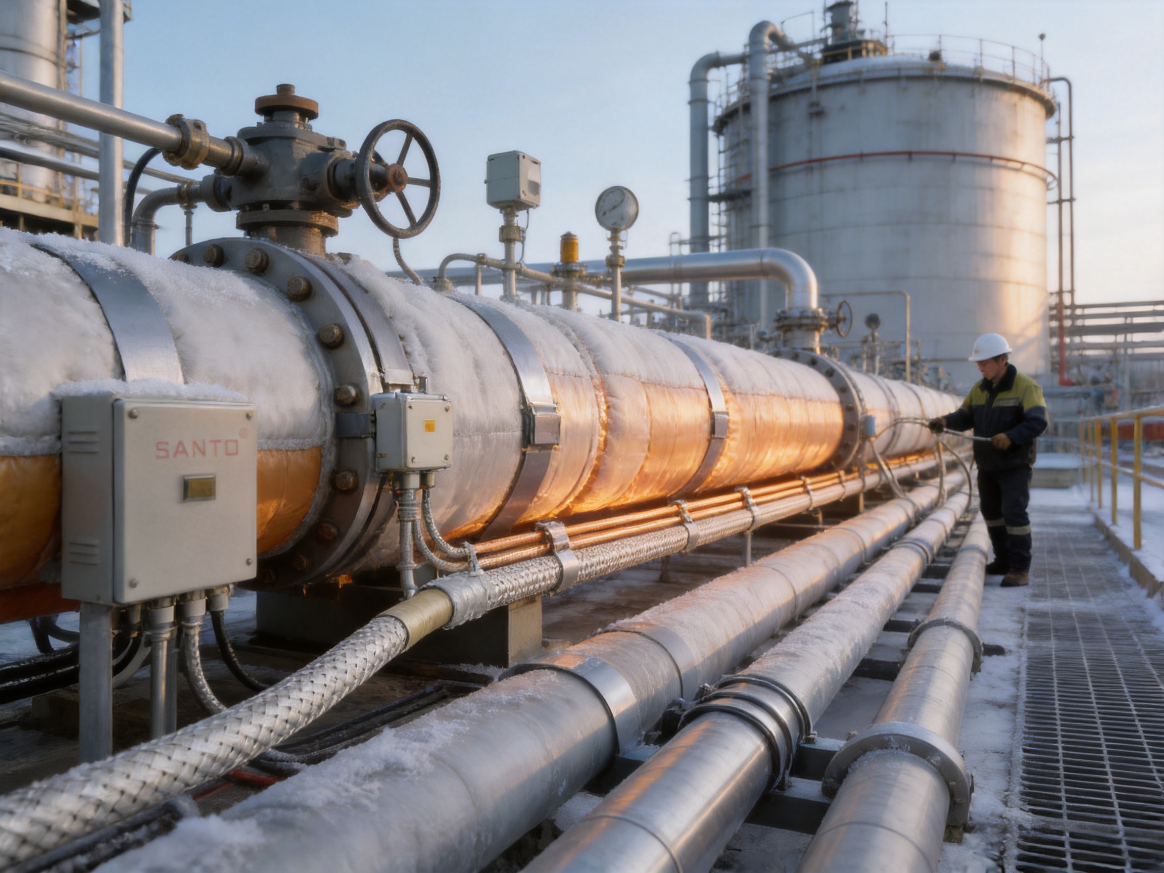
Many general-purpose heating cables use insulation and jackets designed for moderate industrial or commercial environments. Such materials may not provide sufficient resistance to organic solvents, corrosive substances, process vapors, or repeated chemical cleaning. The XPI-1 uses fluoropolymer insulation and a PTFE outer jacket to address this challenge.
This construction can reduce the risk of jacket swelling, embrittlement, cracking, or chemical attack when the cable is selected for a compatible application. Chemical compatibility must always be checked against the exact substances, concentration, temperature, and exposure duration, but the material selection gives the XPI-1 a strong advantage in chemically demanding installations.
With a continuous exposure rating of up to 260°C and an intermittent exposure rating of up to 300°C for the stated duration, the XPI series is intended for temperatures beyond the range of many low-temperature commercial heating products. This makes it appropriate for selected process heat-maintenance, freeze-protection, and viscosity-control systems.
The high-temperature construction also supports installations where the surrounding equipment operates at a high process temperature. The cable must be carefully designed so that its actual sheath temperature, power output, and control limits remain within the permissible range.
The nickel-plated copper braid provides a dedicated low-ohmic earth path. Some basic heating wires have limited mechanical protection or require additional protective arrangements. The XPI-1 integrates the braid into the cable construction, simplifying the creation of a protective bonding path when the system is installed according to electrical standards.
A protective braid does not eliminate the need for insulation resistance testing, earth continuity testing, suitable overcurrent protection, residual-current protection, and correct termination. It does, however, provide a robust conductive shield around the insulated heating core.
The wide model range is another advantage for system designers. Instead of forcing every installation into one or two standard resistance values, the XPI series offers multiple options. This supports more precise matching of circuit length, voltage, current, and heating output.
A wide resistance range can also help reduce unnecessary compromises during system design. Engineers may select a cable that better fits the available power distribution, circuit segmentation, control panel capacity, and physical layout.
The braided layer increases resistance to handling and abrasion compared with a simple insulated heating wire. This is useful in plant environments where cables must be routed around flanges, supports, instruments, valves, and irregular surfaces.
The cable remains a precision electrical product and should not be dragged over sharp edges or crushed beneath clamps. The braid is intended to improve protection, not to permit careless handling. When combined with suitable fixing materials and protective insulation, it supports a durable installation.
The product information identifies regional application levels including Zone 1 and Zone 2 for gas atmospheres and Zone 21 and Zone 22 for dust atmospheres, as well as normal areas. Hazardous-area use requires a complete engineered system. The cable alone does not automatically make an installation safe for every classified location.
The complete heat-tracing system must include suitable terminations, junction boxes, controllers, temperature sensors, glands, protective devices, and installation methods. Equipment selection must correspond to the area classification, gas or dust group, temperature class, ambient conditions, and applicable certification requirements.
In petroleum and chemical facilities, the XPI-1 can be considered for freeze protection and temperature maintenance on process lines, drains, sampling lines, valves, and instruments. It may also be used in selected applications where chemical resistance and elevated-temperature performance are required.
In gas facilities, heat tracing can help prevent freezing, hydrate formation, condensation, or viscosity changes in suitable lines and equipment. The required heating output must be calculated carefully because the thermal behavior of small-bore lines and instrument tubing differs from that of large process pipes.
In dust-classified areas, the installation must prevent excessive surface temperature and accumulation-related hazards. The control system should maintain the equipment within the required temperature limits, and the entire arrangement must be assessed by qualified personnel.
Normal-area applications may include industrial pipe freeze protection, tank temperature maintenance, process equipment heating, outdoor line heating, and other systems where a high-temperature chemically resistant cable is preferred.
| Application environment | Typical heating objective | Important design factors |
|---|---|---|
| Petroleum facilities | Freeze protection and process temperature maintenance | Pipe heat loss, hazardous-area classification, temperature control, chemical exposure |
| Chemical plants | Maintaining flowability and preventing solidification | Chemical compatibility, maximum sheath temperature, insulation, cleaning conditions |
| Gas processing | Preventing freezing, condensation, or hydrate-related problems | Area classification, line size, control accuracy, circuit protection |
| Outdoor industrial systems | Protection against low ambient temperatures | Wind, rain, insulation quality, minimum installation temperature, UV exposure |
| Process vessels and tanks | Maintaining material temperature | Surface coverage, thermal expansion, control zones, access for maintenance |
| Instrument and sampling lines | Maintaining sample or instrument function | Small-bore heat loss, sensor placement, flexible routing, local temperature limits |
A reliable heat-tracing installation begins with a thermal design. The designer should determine the heat loss from the pipe or equipment under the coldest expected ambient condition. Factors normally include pipe diameter, pipe material, process temperature, ambient temperature, wind, insulation type and thickness, cladding, supports, valves, flanges, and the desired maintenance temperature.
The required cable output should include an appropriate engineering margin without exceeding the permitted surface temperature or equipment limit. The XPI series has a stated maximum standard output of 30 W/m, but the practical output for a particular cable depends on its resistance, voltage, circuit length, operating temperature, and control method.
Heat tracing is usually divided into circuits or zones. A circuit should be sized so that its operating current is compatible with the power supply, switching equipment, protective devices, and hazardous-area requirements. Long circuits may create voltage drop or high current depending on the selected resistance. Short circuits may require careful control to prevent excessive local heating.
Temperature sensors should be installed where they represent the actual temperature that must be maintained. A sensor placed too close to the heating cable may respond to cable temperature rather than process temperature. A sensor placed in a poorly insulated or unusually exposed location may cause unnecessary heating. For critical processes, independent high-temperature limiters are recommended.
Heating cables should be positioned so that heat is distributed evenly. Extra cable may be required around valves, supports, flanges, pumps, and other heat sinks. These areas should be treated as separate design features rather than covered randomly. The specified minimum 20 mm spacing between heating lines must be maintained where multiple runs are used.
Thermal insulation should be installed after the heating cable has been inspected and tested. Poor insulation can dramatically increase heat loss, extend operating time, and raise energy consumption. Insulation cladding should protect the cable and insulation system from water ingress, mechanical damage, and environmental deterioration.
The XPI-1 should be transported and stored in a clean, dry location. The cable should remain protected from sharp objects, excessive compression, and contamination. During unwinding, the cable should be allowed to leave the reel smoothly without kinks or twists.
The minimum bending radius at 70°C is specified according to cable diameter. For heating wire diameters below 6 mm, the minimum bending radius is 25 times the heating-wire diameter. For diameters above 6 mm, the minimum bending radius is 6 times the heating-wire diameter. These values should be treated as minimum limits, not normal targets. A larger bend radius is preferable wherever space permits.
The cable should not be folded, sharply creased, stapled through, or clamped in a manner that damages the jacket. Fixing materials should be compatible with the cable and operating temperature. Metal bands, clips, or ties should not cut into the outer jacket.
Before installation, the pipe or equipment surface should be free of sharp projections, oil, dirt, excessive rust, and loose coatings. Welds, flanges, supports, and instrument connections should be examined carefully. Any feature that could abrade or crush the cable should be corrected or protected.
The cable should be routed in accordance with the approved layout. It should remain in close thermal contact with the heated surface where the design requires it, while avoiding direct contact with sharp edges and moving parts.
Insulation resistance should be measured before installation, after installation, after thermal insulation is applied, and during maintenance when appropriate. The measurement method and test voltage should follow the manufacturer’s instructions and applicable electrical standards.
Earth continuity should also be verified through the nickel-plated copper braid. All connections must be properly terminated, sealed, and bonded. Test results should be recorded as part of the commissioning documentation.
The circuit resistance should be compared with the expected value after correcting for temperature where necessary. Resistance tolerance and temperature coefficient must be considered when evaluating measurements.
The manufacturer recommends the use of a 30 mA leakage protection device for maximum safety and fire prevention. Applications with high expected leakage current may require a leakage protection device rated up to 300 mA, subject to the system design and applicable regulations.
Leakage protection selection must be completed by a qualified electrical professional. The device rating should coordinate with circuit current, cable length, insulation characteristics, ambient conditions, switching equipment, and the area classification. All safety performance must be verified before the system is placed into service.
Temperature limiters or reliable design principles must be used to determine and control temperature levels. Constant power cable should not be operated without appropriate temperature management when overheating could damage the process, insulation, cable, or surrounding materials.
Control panels may use thermostats, electronic controllers, contactors, solid-state switching, or other suitable equipment. In hazardous areas, the control and protection arrangement must be appropriate for the classified location. Critical systems may use independent high-limit cutouts in addition to normal temperature control.
The XPI series documentation lists recommended cold-end wire options. An XPI-S cold-end wire may be used as an alternative where appropriate. The cold-end connection must be selected to carry the expected current and withstand the installation environment without creating a weak point in the system.
The listed cold-end options range from 2.5 mm² to 25 mm² cross-sectional area. Their nominal current capacities range from 32 A to 129 A. The corresponding XPI models include XPI-7, XPI-4.4, XPI-2.9, XPI-1.8, XPI-1.1, and XPI-0.8.
| Cross-sectional area | Nominal current | Outside diameter | Approximate resistance at 20°C | Matching XPI model |
|---|---|---|---|---|
| 2.5 mm² | 32 A | 5.5 mm | 7.0 ohm/km | XPI-7 |
| 4 mm² | 42 A | 6.1 mm | 4.4 ohm/km | XPI-4.4 |
| 6 mm² | 54 A | 6.9 mm | 2.9 ohm/km | XPI-2.9 |
| 10 mm² | 73 A | 8.6 mm | 1.8 ohm/km | XPI-1.8 |
| 16 mm² | 98 A | 10.1 mm | 1.1 ohm/km | XPI-1.1 |
| 25 mm² | 129 A | 11.9 mm | 0.8 ohm/km | XPI-0.8 |
Cold-end termination is a critical part of the complete heating system. The transition between the heating section and the power-supply cable must preserve electrical insulation, mechanical strength, moisture resistance, and grounding continuity. Terminations should be made using approved components and procedures rather than improvised field methods.
Santo Thermal Control Technology Co., Ltd. is an industrial heating manufacturer based in Jiangsu Province, China. The company operates in the electric heating and heat-tracing sector and has developed products for petroleum, chemical, gas, construction, solar energy, geothermal cultivation, and other industrial applications.
The company’s product scope includes constant-power electric heating belts, self-regulating heating belts, silicone rubber heating systems, glass-fiber heating belts, MI cables, snow-melting cables, heating wires, tubing-bundle heating products, and related accessories. This product breadth provides a useful foundation for selecting a complete heating solution rather than treating the cable as an isolated component.
According to the supplied company information, the business has more than 35 years of industry experience, annual output exceeding 10,000 units or product items, more than 2,000 distributors, and business coverage in more than 85 areas. These figures indicate an established manufacturing and distribution structure supporting both domestic and international markets.
The company integrates research, design, production, manufacturing, and sales. This integrated approach can improve communication between product development and manufacturing teams. It also supports customization for different voltage levels, resistance values, cable lengths, termination arrangements, temperature requirements, and environmental conditions.
The manufacturer states that it has strengthened new product development, technical guidance, scientific management, quality control, and after-sales service. It also states that the company has passed ISO9001 quality system certification and that its products have obtained national CCC certification. Certification requirements vary by market and product configuration, so customers should request current certificates and confirm that the supplied configuration is covered.
Santo reports cooperation in product research with Harvard University in the United States and describes itself as a high-technology enterprise in Jiangsu Province. The company’s development history includes work on self-regulating temperature systems, nano far-infrared heaters, carbon-fiber parallel heating cables, and other electric heating technologies.
Research and development experience across multiple heating technologies can be valuable when designing constant power products. Heat tracing involves more than conductor selection. It requires understanding thermal transfer, insulation, temperature control, electrical protection, material compatibility, installation methods, and service conditions.
The company’s stated development activities include the establishment of an irradiation center in 2013, the creation of the SANTO brand in 2016, and the construction of additional factory and product simulation testing facilities beginning in 2022. These activities reflect an emphasis on process development and product verification.
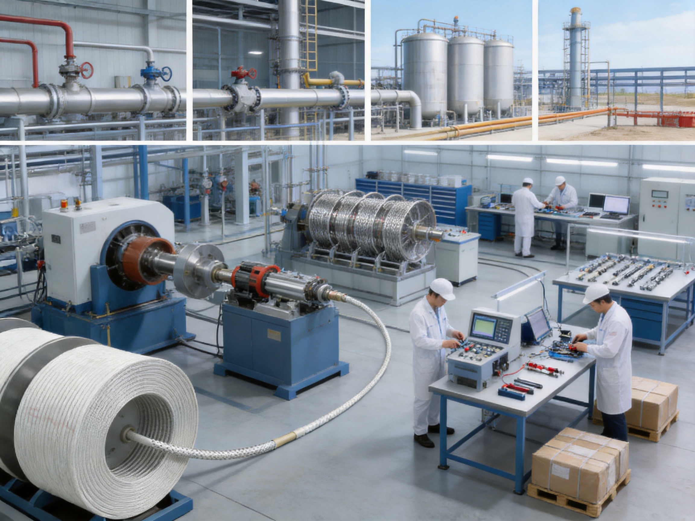
A high-temperature heating cable such as the XPI-1 requires controlled manufacturing at several stages. The conductor must be prepared with consistent dimensions and plating coverage. Stranding must maintain the required construction without damaging the conductor. Insulation layers must be applied uniformly to avoid thin areas, voids, or excessive eccentricity.
The metallic braid must maintain adequate coverage and continuity along the cable length. Its resistance must remain low enough to provide an effective protective earth path. The PTFE jacket must be applied with controlled thickness and surface quality to provide consistent protection against environmental exposure.
In-process inspection is important because many cable defects are not visible after the final jacket has been applied. Dimensional checks, electrical resistance measurements, insulation tests, braid continuity checks, surface inspections, and sampling tests can help identify problems before shipment.
For customized orders, manufacturing control should include review of the required voltage, resistance, cable length, power output, operating temperature, cold-end arrangement, reel weight, packaging, labels, and documentation. This product information notes that supply length depends on the resistance model and that each section may be 1,000 metres, with a maximum reel weight of 120 kilograms. Actual supply arrangements should be confirmed before ordering.
The XPI-1’s reliability comes from the interaction of its materials and manufacturing controls. Nickel-plated conductors support long-term electrical stability in high-temperature conditions. Fluoropolymer insulation protects against electrical breakdown and chemical exposure. The braided layer supports grounding and mechanical protection. The PTFE jacket forms a durable external barrier.
Reliability also depends on consistency. A cable with the correct nominal resistance but irregular insulation thickness may not perform consistently. A braid with interrupted continuity may not provide the expected earth path. A jacket with surface defects may allow moisture or chemicals to reach the underlying layers. For this reason, production inspection and documentation are essential elements of the product value.
Customers evaluating suppliers should consider more than catalogue specifications. They should review quality certificates, routine test procedures, batch records, traceability, product labeling, packaging standards, termination capabilities, technical support, and the supplier’s ability to provide replacement or repeat production.
Santo’s experience across multiple electric heating product categories provides a foundation for these services. Its stated business model combines manufacturing, technical development, sales, and after-sales support, which can help customers coordinate product selection and project execution.
Industrial heat-tracing projects often require customization. Pipe sizes, line lengths, ambient temperatures, hazardous-area classifications, available voltages, power distribution systems, and control philosophies vary from project to project. A standard catalogue cable may be suitable, but the complete system frequently requires engineered adaptation.
Potential customization areas include resistance selection, cable length, circuit segmentation, cold-end wire selection, end termination, connection kits, reel configuration, labels, packaging, and technical documentation. A supplier with several heating technologies can also recommend a different product category where constant power is not the best choice.
Constant power cable is particularly useful where the required heat output is known and the cable can be arranged in a controlled circuit. Self-regulating cable may be preferred for other applications with variable heat demand or overlapping installation conditions. Silicone rubber, glass-fiber, MI, or snow-melting systems may be more suitable for specialized temperature or environmental requirements.
Technical consultation should begin with project information such as pipe or equipment dimensions, material, insulation details, operating temperature, minimum ambient temperature, target maintenance temperature, chemical exposure, hazardous-area classification, available voltage, desired circuit length, and control method.
A well-designed XPI-1 installation should be included in the facility’s preventive maintenance program. Visual inspections can identify damaged insulation cladding, loose fixing points, water ingress, exposed cable, damaged junction boxes, or signs of overheating.
Electrical tests should be repeated at suitable intervals and after maintenance work. A declining insulation resistance value may indicate moisture ingress, mechanical damage, chemical attack, or a termination problem. Earth continuity should also be checked to confirm that the protective braid and bonding system remain intact.
Control devices should be tested to confirm that normal temperature regulation and independent high-temperature shutdown functions operate correctly. Sensors should be inspected for displacement, damage, or poor thermal contact. Protective devices should be tested according to the facility’s electrical safety program.
Insulation and cladding deserve particular attention. Damaged insulation can increase heat loss and expose the heating cable to water or mechanical stress. Replacing damaged insulation promptly can reduce energy consumption and extend the service life of the heating system.
If a fault occurs, the circuit should be isolated before inspection. Repairs should use approved components and procedures. Cutting into the cable or creating an unapproved splice can compromise insulation, grounding, chemical resistance, and hazardous-area compliance.
Heating cable efficiency depends on the relationship between power output and heat loss. A properly selected XPI-1 circuit provides enough heat to maintain the required temperature without excessive energy use. Accurate thermal calculations and good insulation are therefore as important as the cable itself.
Automatic temperature control can reduce unnecessary operating time. Instead of continuously energizing a circuit at full output, the system can activate heating when the monitored temperature approaches the lower control limit. In areas with changing ambient conditions, this can improve energy management.
Zone control is another practical approach. Pipes, valves, instruments, and equipment with different heat-loss characteristics can be separated into control zones. Each zone can then be designed and regulated according to its actual requirements.
Proper installation reduces energy losses caused by poor contact, uneven spacing, insufficient insulation, exposed junctions, or incorrectly positioned sensors. A high-quality cable cannot compensate for a poorly insulated or badly controlled system.
Before purchasing the XPI-1 or another XPI series model, the buyer should define the application requirements clearly. The following questions help establish whether the product is appropriate.
What surface or process temperature must be maintained?
What is the lowest expected ambient temperature?
What is the maximum temperature of the equipment or process?
Will the cable be exposed to organic substances, corrosive chemicals, cleaning fluids, moisture, or process vapors?
Is the installation in a normal area or a classified gas or dust area?
What voltage is available?
What circuit length and power output are required?
What resistance model best matches the voltage and current limits?
What cold-end wire and termination system are required?
What type of temperature sensor, controller, limiter, and leakage protection device will be used?
What insulation material, thickness, and weatherproof cladding will be installed?
What documentation, certification, inspection records, and delivery schedule are required?
Answering these questions before placing an order reduces the risk of selecting a cable that is electrically unsuitable, thermally undersized, chemically incompatible, or difficult to certify for the intended location.
The XPI-1 is a series constant power heating cable intended for industrial heat tracing. It uses a nickel-plated stranded conductor, high-temperature fluoropolymer insulation, a nickel-plated copper braid, and a PTFE outer jacket.
Nickel plating helps protect the high-temperature conductor against oxidation and supports long-term service in elevated-temperature and corrosive environments. The stranded construction also supports practical installation flexibility within the specified bending limits.
The nickel-plated copper braid provides additional mechanical protection and a low-ohmic protective earth path. It should be connected and tested as part of the complete electrical safety system.
PTFE provides strong resistance to many organic and corrosive substances and offers high-temperature performance. It helps protect the internal insulation and conductor from the surrounding environment.
The supplied product information identifies applications associated with Zone 1, Zone 2, Zone 21, and Zone 22. However, hazardous-area suitability applies to the complete engineered system, including cable, terminations, control equipment, glands, junction boxes, and protective devices. The current certification and project requirements must be verified before use.
The stated maximum exposure temperature is 260°C for continuous service and 300°C for intermittent service up to 1,000 hours. The actual operating temperature must be controlled according to the application and the manufacturer’s technical instructions.
The standard maximum power output is listed as 30 W/m. The permitted output for a specific installation depends on the cable model, voltage, circuit length, heat loss, surface temperature, insulation, and control system.
Selection should be based on the required voltage, circuit length, operating current, power per metre, temperature coefficient, and thermal design. A qualified engineer or the manufacturer’s technical team should review the calculations before production or installation.
At 70°C, the minimum bending radius is 25 times the heating-wire diameter when the diameter is below 6 mm, and 6 times the diameter when the diameter is above 6 mm. A larger radius is recommended whenever practical.
The manufacturer recommends a 30 mA leakage protection device for maximum safety and fire prevention. Where high leakage current is expected from the design, a device up to 300 mA may be considered subject to qualified engineering review and applicable regulations.
Heat-tracing cable is commonly installed beneath thermal insulation, but the exact arrangement must follow the approved design. The cable must be fixed without damage, tested before covering, and protected from moisture and mechanical hazards by a suitable insulation and cladding system.
The company specializes in heating cable production and provides different resistance models, cable configurations, cold-end options, and related electric heating products. Customers should provide complete project requirements so the correct configuration and delivery schedule can be confirmed.
The supply length depends on the resistance model and reel limitations. The supplied information states that each section may be 1,000 metres and that the maximum reel weight is 120 kilograms. Actual lengths and packaging should be confirmed for each order.
Recommended checks include visual inspection, conductor resistance measurement, insulation resistance testing, protective braid continuity testing, termination inspection, control-system verification, sensor verification, and leakage-protection testing. Test results should be recorded for commissioning and future maintenance.
The XPI-1 series constant power heating cable is designed for industrial applications where ordinary heating wires may not provide enough temperature capability, chemical resistance, mechanical protection, or grounding performance. Its nickel-plated stranded conductor supports high-temperature durability, while the fluoropolymer insulation provides electrical separation in severe environments.
The nickel-plated copper braid adds mechanical strength and a low-resistance earth path. The PTFE outer jacket offers a further barrier against organic and corrosive substances. Together, these layers create a robust cable construction for engineered heat-tracing systems in petroleum, chemical, gas, process, outdoor, and other industrial applications.
The wide resistance range allows designers to match the cable to different voltages, circuit lengths, and power requirements. Technical characteristics such as a 260°C continuous exposure temperature, 300°C intermittent exposure capability, -70°C minimum installation temperature, up to 30 W/m standard output, and up to 450/750 VAC rated voltage make the series suitable for demanding projects when correctly specified.
Santo Thermal Control Technology combines electric heating research, manufacturing, quality management, customization, and international sales support. Its broad product portfolio and stated industry experience provide customers with access to multiple heating technologies and related accessories.
Successful performance depends on more than the cable specification. Thermal calculations, correct resistance selection, compatible materials, appropriate temperature control, protective earthing, leakage protection, insulation, commissioning tests, and preventive maintenance must all be integrated into the final system. When these requirements are properly addressed, the XPI-1 can provide dependable and durable heat tracing for challenging industrial environments.
Santo Thermal Control Technology Co., Ltd., XPI Product Specification, technical product documentation.
Santo Thermal Control Technology Co., Ltd., XPI Constant Watt Technology, technical product documentation.
Santo Thermal Control Technology Co., Ltd., XPI Heating Systems, application and system documentation.
Santo Thermal Control Technology Co., Ltd., XPI Product Description, product construction and selection information.
EN 50019, Electrical apparatus for potentially explosive atmospheres, protection by increased safety, referenced for impact-resistance information.
ISO 9001, Quality management systems, requirements for manufacturing and service organizations.
General industrial heat-tracing design principles covering thermal-loss calculation, temperature control, insulation, electrical protection, commissioning, and maintenance.
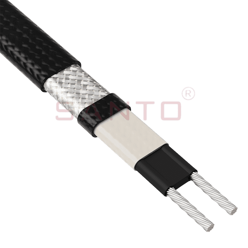
The SANTO UFA range of self-regulating heating cables is mainly used for frost protection of pipes and vessels but can also be used to maintain processes up to 65°C. These heating cables are available...
See Details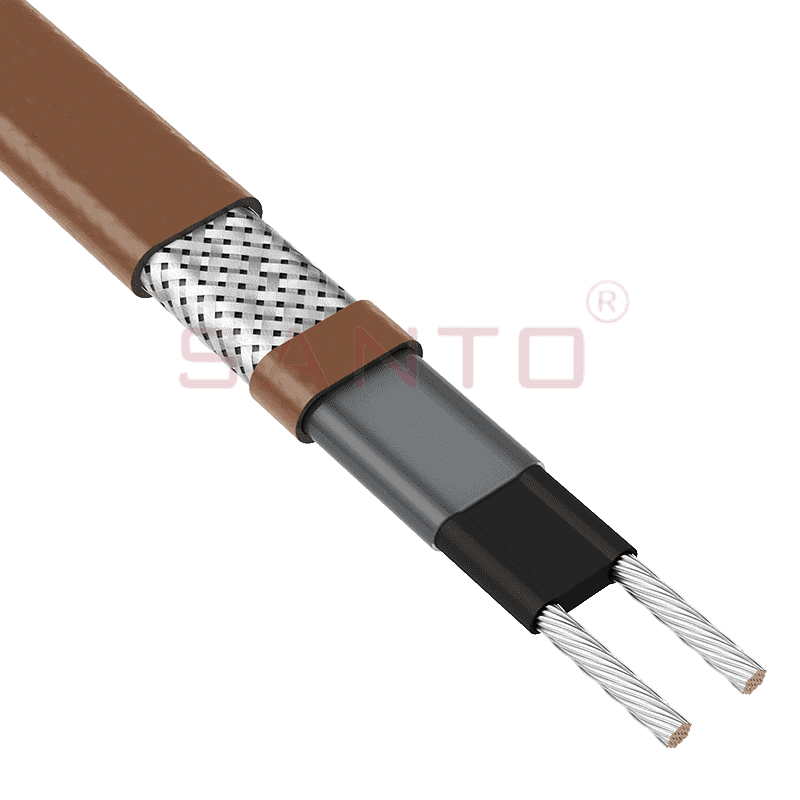
The SANTO UFB range of self-regulating heating cables is mainly used for frost protection of pipes and vessels requiring a higher power output than the UFA heating cables can supply. They can also be ...
See Details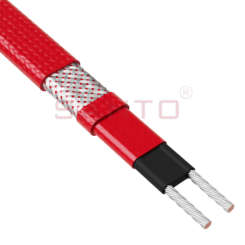
The SANTO UFC range of self-regulating heating cables is used for frost protection of pipes and vessels that require steam cleaning. They can also be used to maintain processes up to 121°C. These heat...
See Details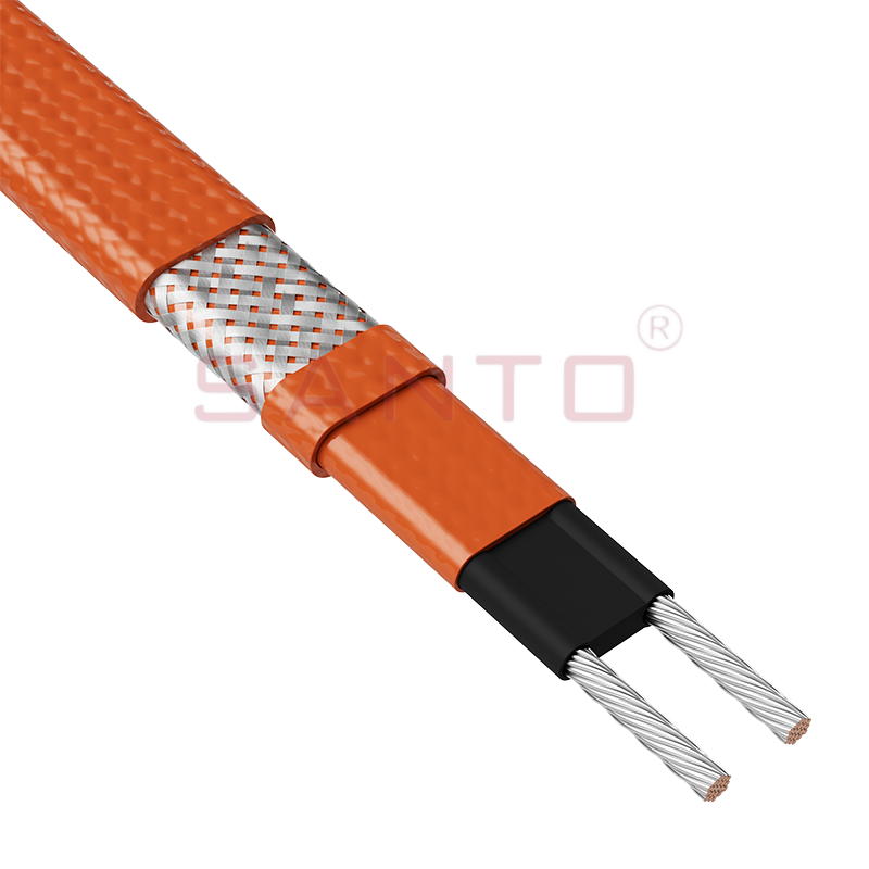
The SANTO UFO range of self-regulating heating cables is mainly used for frost protection of pipes and vessels that require steam cleaning . They can also be used to maintain processes up to 150°C. Th...
See Details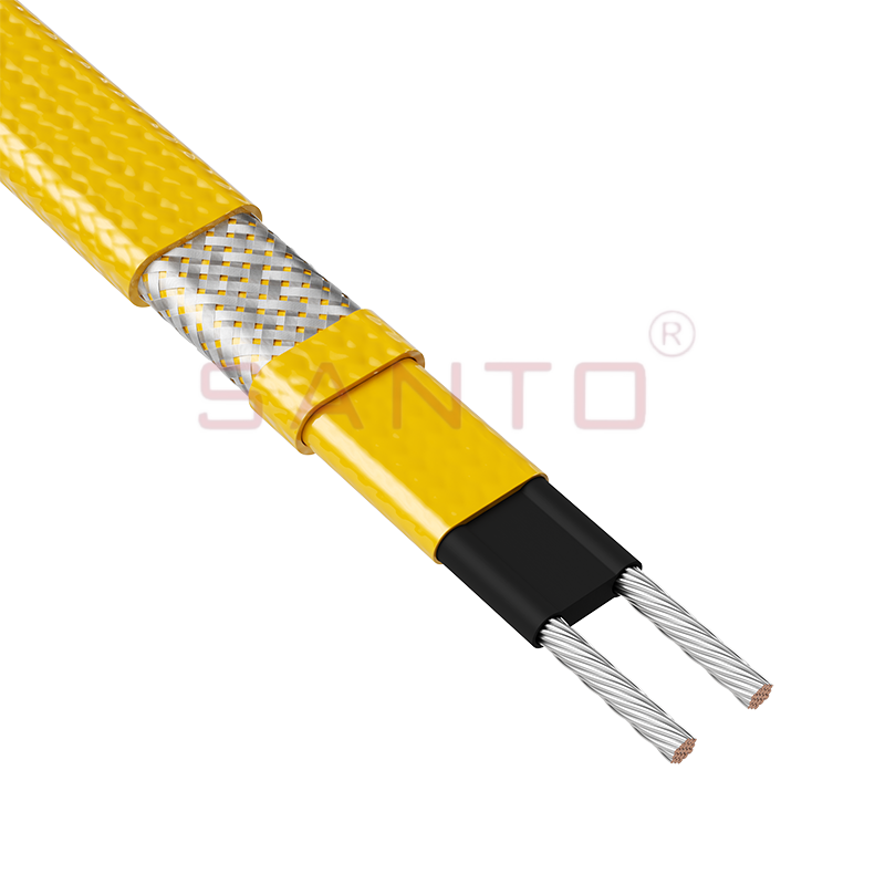
The SANTO UFD series of self-regulating heating cables are mainly used for freeze protection of pipes and vessels, but can also be used to maintain processes up to 200°C. These heating cables are avai...
See Details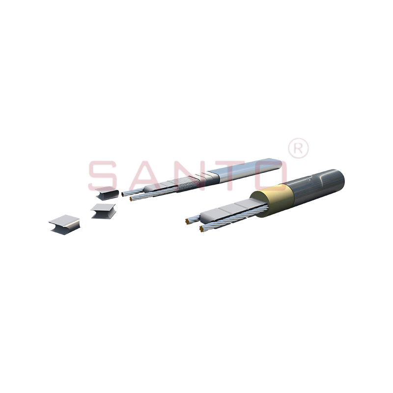
SANTO UFY heating wire is suitable for applications that maintain process temperatures up to 260 ℃ and can be steam blown; The self-regulating and parallel circuit heating wires of the UFY series are ...
See Details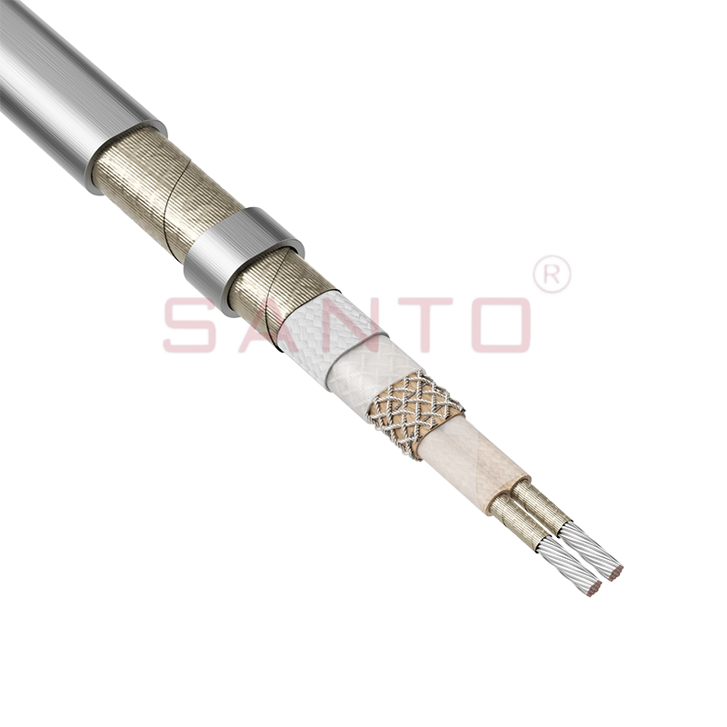
The SANTO UFM series self-regulating heating cables are mainly used for freeze protection of pipes and vessels, but can also be used to maintain processes up to 400°C. These heating cables are availab...
See Details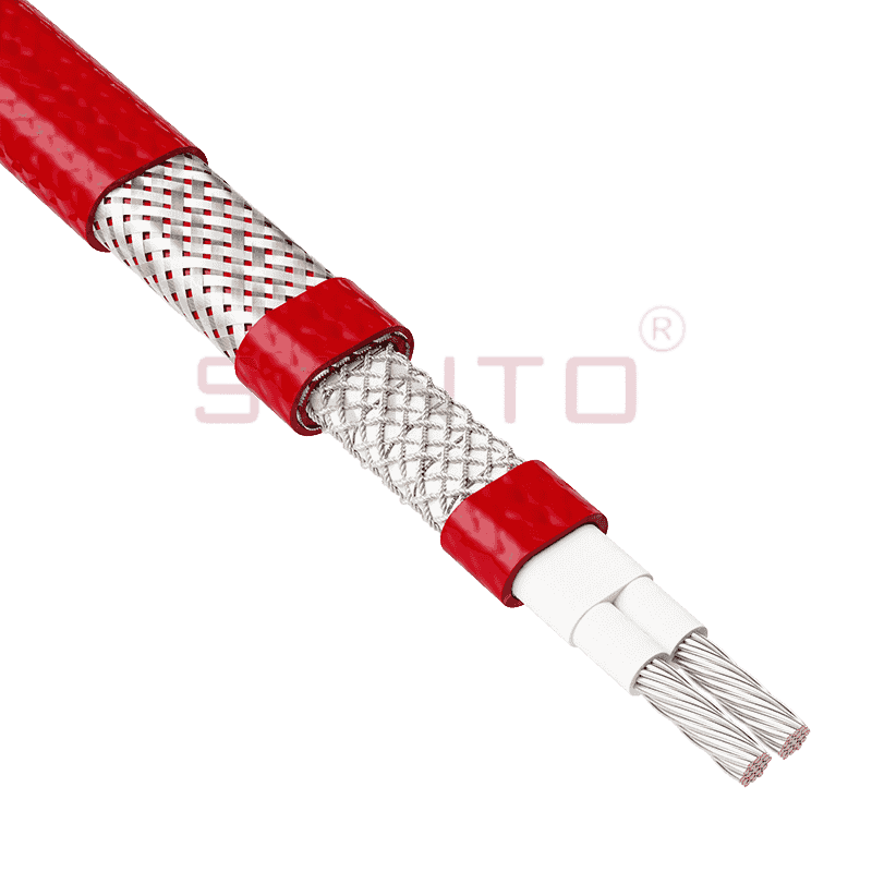
The SANTO ACC range of power-limiting heating cables is mainly used for temperature maintenance of processes and offers the advantage of a high power output at high temperatures which can reduce the n...
See Details
The stranded high temperature conductor is nickel plated to ensure a long life at elevated temperatures in corrosive environments. It is electrically isolated using an innovative sandwich construction...
See Details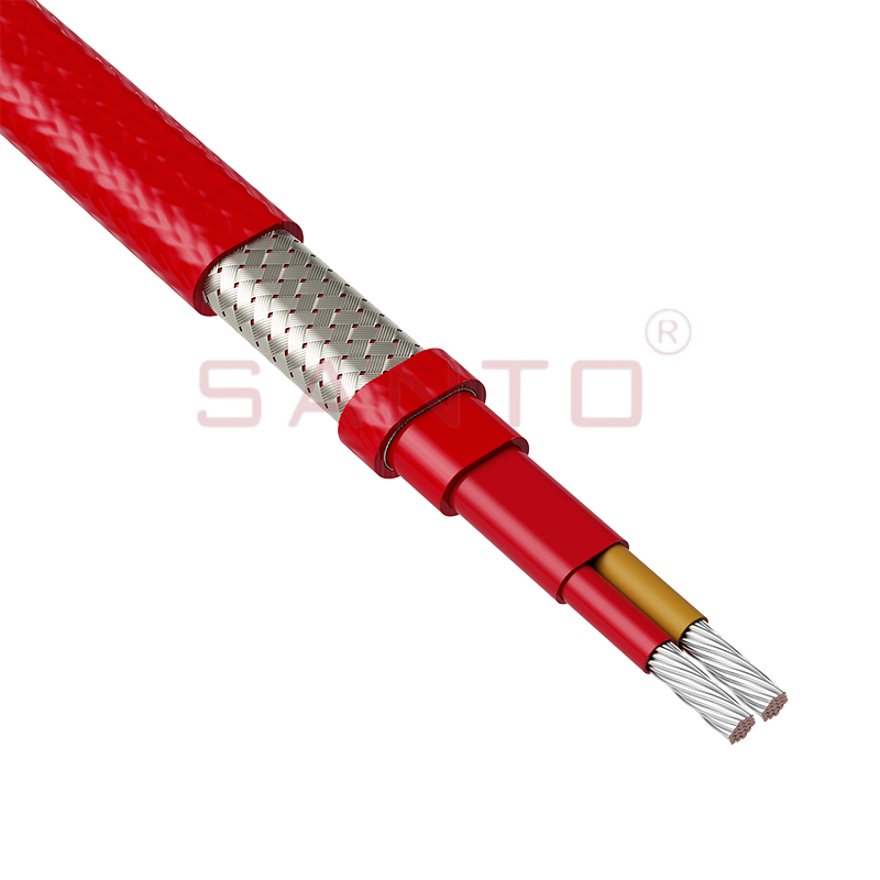
The stranded high temperature conductor is nickel plated to ensure a long life at elevated temperatures in corrosive environments. It is electrically isolated using an innovative sandwich construction...
See Details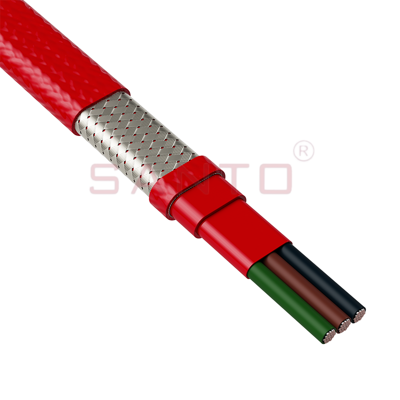
The stranded high temperature conductor is nickel plated to ensure a long life at elevated temperatures in corrosive environments. It is electrically isolated using an innovative sandwich construction...
See Details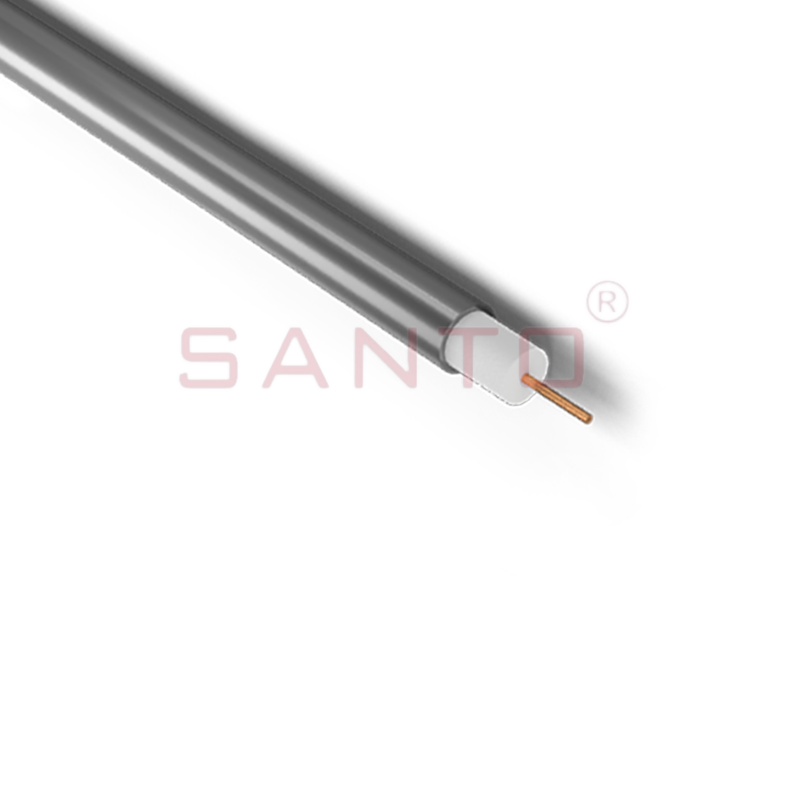
SANTO HAx mineral insulated (MI) Alloy 825 series heating cables are suitable for use in hazardous areas. They have been designed for use in freeze protection and temperature maintenance applications ...
See Details
Santo electric heating strips are widely used in key industries in China.

