 English
 English
 русский
 日本語
 Español
 中文简体

The SANTO UFA range of self-regulating heating cables is mainly used for frost protection of pipes and vessels but can also be used to maintain processes up to 65°C. These heating cables are available...
See Details
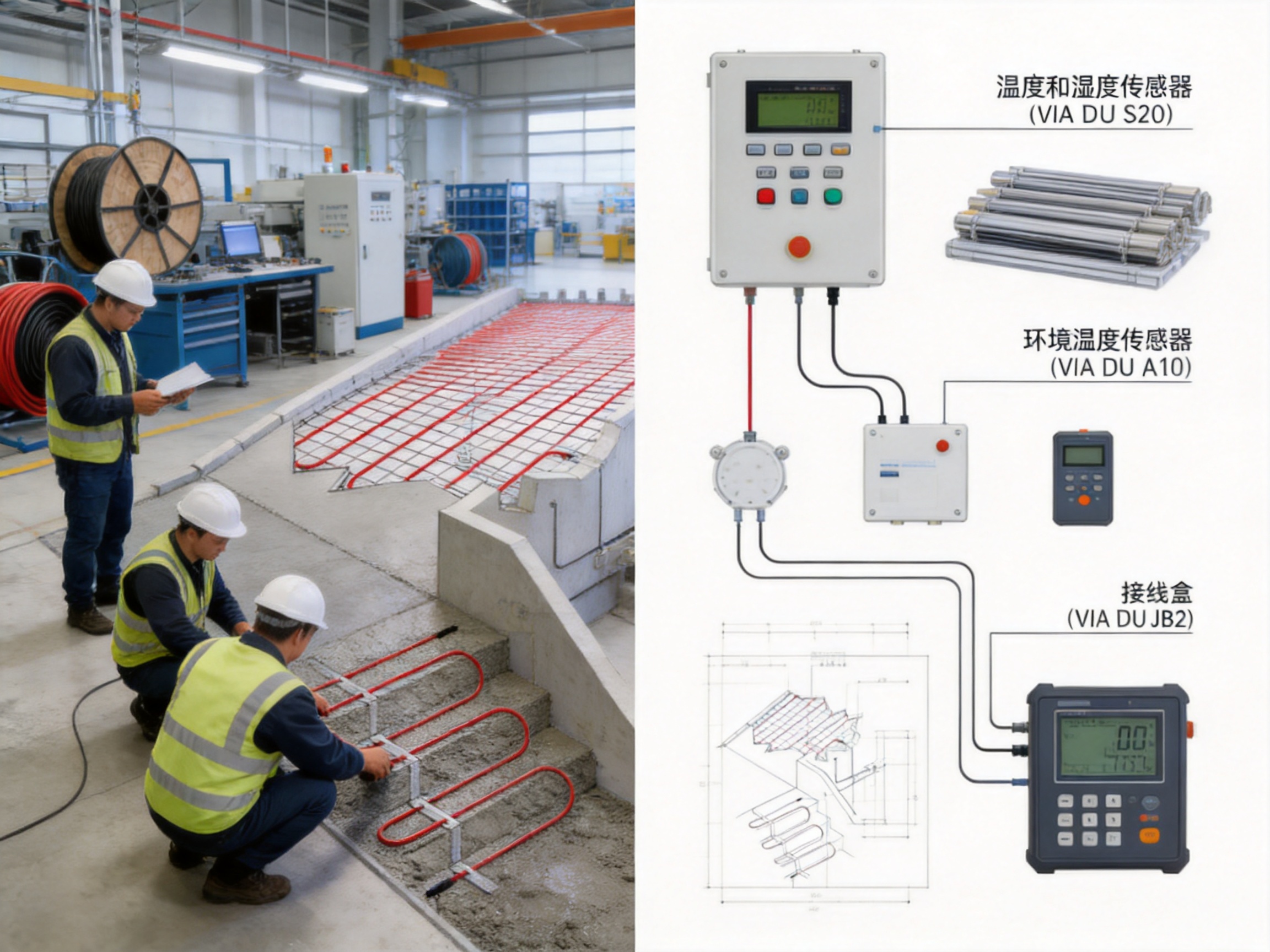
Snow, ice, and freezing water create serious risks for roads, ramps, walkways, stairs, loading areas, and vehicle entrances. A surface that appears merely wet can become hazardous when temperatures fall below freezing. For commercial buildings, industrial sites, transport facilities, residential developments, and public infrastructure, reliable snow and ice prevention is therefore an important part of winter safety planning.
The SANTO UFP self-regulating heating and snow melting cable is designed for ground heat tracing applications where dependable deicing, flexible installation, and intelligent energy management are required. It can be installed beneath concrete, in sand or cement beds, and under asphalt. When paired with the VIA-DU-20 intelligent control unit, the system responds not only to temperature but also to moisture and snow conditions. This approach helps prevent unnecessary operation during cold but dry weather.
Unlike conventional systems that operate according to a fixed temperature setting, a properly configured self-regulating snow melting system can adapt its heat output to changing conditions. The result is a practical combination of safety, operating efficiency, installation flexibility, and long-term reliability.
Content
Outdoor surfaces are exposed to rapidly changing weather. Air temperature, ground temperature, humidity, precipitation, wind, sunlight, and surface construction all affect the formation and persistence of ice. A control method based only on air temperature cannot accurately identify every situation in which heating is necessary.
For example, a ramp may remain dry at a low temperature and require no heating. In another situation, a small amount of melting snow may create water on the same ramp. If the surface temperature then falls below freezing, the water can quickly become black ice. A control unit that detects only temperature may activate too early, too late, or for too long. A system that combines temperature and moisture sensing is better positioned to respond to the actual surface condition.
The SANTO snow melting solution is intended to address this challenge. The heating cable provides distributed heat beneath the treated surface, while the control system monitors the environmental conditions associated with snow and ice formation. The system can be used to reduce the need for manual snow removal, limit the use of chemical deicers, and improve access during winter weather.
Typical applications include:
• Vehicle ramps and inclined driveways
• Road entrances and lanes
• Pedestrian walkways
• Steps and stairways
• Loading platforms
• Parking access areas
• Garage entrances
• Industrial yards
• Bridge approaches and exposed paved sections
• Ground heat tracing zones around buildings and facilities
In each application, the cable layout, power density, surface construction, control strategy, and local climatic conditions should be evaluated by qualified technical personnel.
The SANTO UFP self-regulating heating and snow melting cable is a ground heating product developed for outdoor deicing and snow melting. Its main function is to transfer controlled electrical heat to the surrounding installation layer so that snow and ice can melt before they accumulate or create dangerous surface conditions.
The cable can be designed for complex areas because it may be arranged according to the shape of the heated zone. Ramps, curved entrances, irregular walkways, and other non-rectangular surfaces can be accommodated more easily than with rigid prefabricated heating components. The system can also be supplied with factory-prepared tail-end connection units, while some cable configurations can be cut to the required length and terminated on site in accordance with approved installation procedures.
This flexibility is particularly valuable in retrofit projects and construction areas where the final surface dimensions may differ from the original design. Instead of forcing a standard mat into an unsuitable shape, installers can plan the cable route around edges, obstacles, joints, drains, and other site features.
The product is intended to work as part of a complete system rather than as an isolated cable. A complete installation normally includes the heating cable, power supply, termination components, temperature and moisture sensors, control equipment, electrical protection, and an integrated control panel where required.
The principal advantage of a self-regulating heating cable is its ability to respond to temperature changes along its length. In areas that become warmer, the cable can reduce its heat output. In colder areas, it can provide comparatively more heat. This behavior helps the heating system respond to local conditions instead of operating at one uniform output under every circumstance.
Outdoor surfaces rarely experience perfectly uniform conditions. One part of a ramp may be exposed to wind, while another part is protected by a wall. A shaded section may remain colder than a section receiving sunlight. Drainage patterns can also cause water to collect in specific locations. A cable with self-regulating characteristics is well suited to these variable conditions because its output can adjust along the heated area.
Self-regulating operation can provide several practical benefits:
• Better adaptation to local temperature differences
• Lower risk of excessive heating in comparatively warm sections
• Improved energy management when combined with an intelligent controller
• Greater flexibility for irregular surface layouts
• Reduced dependence on a single fixed operating condition
It is important to distinguish self-regulating behavior from a complete automatic control strategy. The cable can adjust its output in response to temperature, but system-level energy savings depend on correct sensor placement, controller settings, electrical design, surface construction, and operating conditions. The VIA-DU-20 control unit adds an additional layer of control by considering ground temperature, ground humidity, and ambient temperature.
The VIA-DU-20 control unit is designed to make the snow melting system more responsive to real winter conditions. Its sensor block combination can measure ground temperature, ground humidity, and ambient wall temperature. These measurements are used together to determine whether the surface is likely to be affected by snow, ice, or water.
Traditional systems often start heating whenever the measured temperature falls below a selected set point. This method is simple, but it may cause the system to operate during cold, dry periods when no snow or water is present. Unnecessary operating time increases energy consumption and may raise the cost of ownership.
By contrast, an intelligent moisture-and-temperature strategy can keep the heating system off when the surface is cold but dry. When moisture or snow is detected under suitable freezing conditions, the control unit can activate the heating circuit. This helps direct energy toward the periods when it is most useful.
The available material indicates potential energy savings of up to 80 percent compared with standard constant-temperature control. Actual savings depend on climate, surface exposure, insulation, cable layout, operating settings, system capacity, and the frequency of snow and ice events. The stated figure should therefore be treated as an application-dependent potential rather than a universal result.
Even when the controller is not operating, the sensors continue to provide valuable information about the treated zone. Properly installed sensors can help the system distinguish between a cold but safe surface and a cold, wet surface that presents a higher risk of icing.
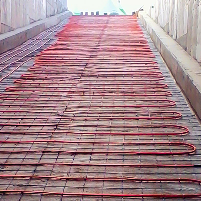
SANTO UFP Self regulating heating and snow melting cable
A conventional temperature-only system may operate for long periods simply because the air or ground temperature has dropped below a preset level. This can happen overnight, during dry cold weather, or after a snow event has already ended. The SANTO solution combines temperature and moisture information so that heating can be concentrated on actual snow and ice conditions.
Reduced unnecessary operation can lower electricity consumption and may also reduce thermal stress on the surface system. The most important benefit, however, is that the equipment is operated according to a more meaningful assessment of winter risk.
Standard heating mats are convenient for regular rectangular spaces, but they can be difficult to use around corners, curves, drains, posts, expansion joints, and irregular boundaries. The SANTO UFP cable can be arranged according to the shape of the area, making it suitable for ramps, curved driveways, narrow paths, and other complex zones.
Design flexibility also allows the heated area to be divided into zones. A project may require more heating near a shaded entrance, drainage channel, steep ramp, or frequently used pedestrian crossing. With an appropriately engineered layout, different areas can be addressed according to their exposure and safety requirements.
The system can be installed in sand or cement mixtures and can also be installed directly beneath asphalt when the design and installation process are suitable for that application. This makes it adaptable to both new construction and certain renovation projects.
Installation beneath concrete may be appropriate for sidewalks, steps, loading areas, and building entrances. Sand-bed installation can provide a practical arrangement beneath paving systems or selected surface assemblies. Asphalt applications require careful attention to cable temperature limits, compaction methods, paving procedures, and the recommendations of the cable manufacturer and paving contractor.
Ground heating cables are installed in environments where they may be exposed to cement, sand, moisture, mechanical pressure, and construction activity before the final surface is completed. The SANTO snow melting system is designed with these demanding conditions in mind.
Durability depends on more than the cable jacket. The complete design must include suitable insulation, electrical protection, mechanical handling procedures, correct bending limits, secure connections, and testing before and after surface installation. The product’s factory-supplied tail-end connection units can simplify termination planning and help reduce the possibility of inconsistent field connections.
Manual shoveling and mechanical snow clearing can be labor-intensive, especially at stairs, steep ramps, narrow paths, loading areas, and entrances that must remain open. Chemical deicers may corrode metal, affect concrete, damage vegetation, or create environmental concerns. A snow melting cable system offers an alternative method for managing winter precipitation.
The system does not eliminate the need for site inspection or emergency snow removal during extreme storms. However, it can reduce accumulation and help maintain safer access when it is correctly designed and activated at the appropriate time.
Ramps are among the most important locations for snow melting. A small amount of ice on an inclined surface can cause vehicles to lose traction. This is especially important at parking garage entrances, service roads, hospital access ramps, warehouse yards, and residential driveways.
The cable layout should consider the direction of vehicle travel, wheel paths, drainage, turning zones, and areas where snow is likely to accumulate. A ramp may also need additional attention near the bottom, where water can collect, or near a shaded side where ice remains longer.
Road snow melting applications can help maintain access to industrial facilities, logistics centers, emergency routes, and private roads. In these situations, a system may be designed as a large-area installation with multiple electrical zones and a centralized control panel.
Large installations require detailed load calculations and coordination with the site electrical system. The design team must consider the available supply, circuit capacity, ground conditions, drainage, surface thickness, local weather data, and the required response time.
Pedestrian areas require special attention because even a thin layer of ice can create a fall hazard. Heating cables can be installed below walkways, steps, entrance platforms, and narrow paths. The cable arrangement should provide even heating while avoiding damage at construction joints and transitions.
Steps may require individual planning for each tread and riser. Sensor placement is also important because an exposed stairway may experience different weather conditions from a nearby entrance sheltered by a canopy.
Factories, distribution centers, warehouses, and commercial facilities often need dependable access throughout the winter season. Snow and ice can delay deliveries, restrict forklift movement, block emergency routes, and increase liability exposure.
A ground heat tracing system can be integrated into a broader site safety plan. Frequently used zones can be prioritized, while less critical areas can remain unheated or be operated under separate controls. This zoning approach can help balance safety requirements and energy management.
Every snow melting project should begin with a site assessment. The assessment should identify the surface type, dimensions, slope, drainage, exposure, local weather, available electrical power, and the expected level of service. The designer should also identify areas where snow is likely to be blown or deposited, such as the lower part of a ramp or the side of a wall.
The cable spacing determines the distribution of heat across the surface. Closer spacing generally increases the installed heat output per unit area, while wider spacing may be suitable for lower-demand zones. Spacing must be selected according to the target surface temperature, snowfall conditions, construction materials, and required melting performance.
The following design factors should be considered:
• Surface area and geometry
• Concrete, asphalt, sand, paver, or composite construction
• Local snowfall and freezing conditions
• Surface drainage and water flow
• Slope and vehicle loading
• Cable spacing and circuit length
• Electrical supply and protective devices
• Sensor locations
• Control panel location
• Expansion joints and movement joints
• Construction sequence
• Cable protection during installation
• Testing and commissioning requirements
For a concrete installation, the cable is typically secured in the planned arrangement before the concrete is poured. It should not be placed where it can be cut, crushed, or displaced by reinforcement, formwork, tools, or concrete placement equipment. The cable must remain at the specified depth to provide even heat transfer.
For sand-bed or paver applications, the installation team should prevent sharp objects and excessive mechanical movement from damaging the cable. The bedding layer should be prepared according to the surface design, and the finished paving system should not impose loads beyond the product’s approved limits.
For asphalt applications, the project must be carefully coordinated with the paving contractor. Hot asphalt, compaction equipment, and construction traffic can expose the cable to significant thermal and mechanical stress. The selected cable must be suitable for the intended paving process, and the installation method should follow the manufacturer’s technical requirements.
Electrical connections are critical to system safety and service life. Factory-supplied tail-end connection units can reduce field assembly work and help provide consistent termination quality. Where cable cutting and on-site termination are permitted, the process must be completed by qualified personnel using approved components and procedures.
Connections should be protected against moisture ingress and mechanical damage. They should be positioned where they can be safely installed within the surface assembly or accessible service area, depending on the design. Unapproved alterations, improvised joints, or unprotected terminations can compromise the entire system.
Testing should be performed before installation, during installation, and after the surface has been completed. Typical checks may include conductor continuity, insulation resistance, cable resistance, sensor operation, connection integrity, and control unit function.
Test results should be documented and retained with the project records. If a cable is damaged during concrete placement, asphalt paving, or other construction activity, early testing can identify the issue before the area is placed into service.
SANTO Thermal Control Technology Co., Ltd. combines product development, manufacturing, technical guidance, and sales within the electric heating industry. The company has more than 35 years of industry experience and produces a broad range of electric heating products, including self-regulating heating belts, constant-power heating products, silicone rubber heating systems, glass fiber heating products, MI cables, snow melting cables, and related accessories.
This product range provides a manufacturing foundation for developing heating solutions for different temperatures, environments, power requirements, and installation conditions. A company that works across multiple heating technologies can draw on experience with conductor design, insulation systems, shielding, termination, temperature control, and application engineering.
The company states that it has an annual output exceeding 10,000 units or product systems, works with more than 2,000 distributors, and serves customers in more than 85 areas. These figures indicate a broad commercial network and experience supporting different market requirements.
SANTO has also reported cooperation in product research with Harvard University in the United States. Its development history includes the establishment of an irradiation center, the development of self-limiting temperature nano far-infrared heating technology, and the invention of a carbon fiber parallel heating cable. These activities reflect a continuing emphasis on product innovation and material research.
The company has passed ISO9001 quality management system certification, and its products have obtained national CCC certification. Certification does not replace project-specific engineering or installation requirements, but it provides evidence that the company has established formal processes for quality management and product control.
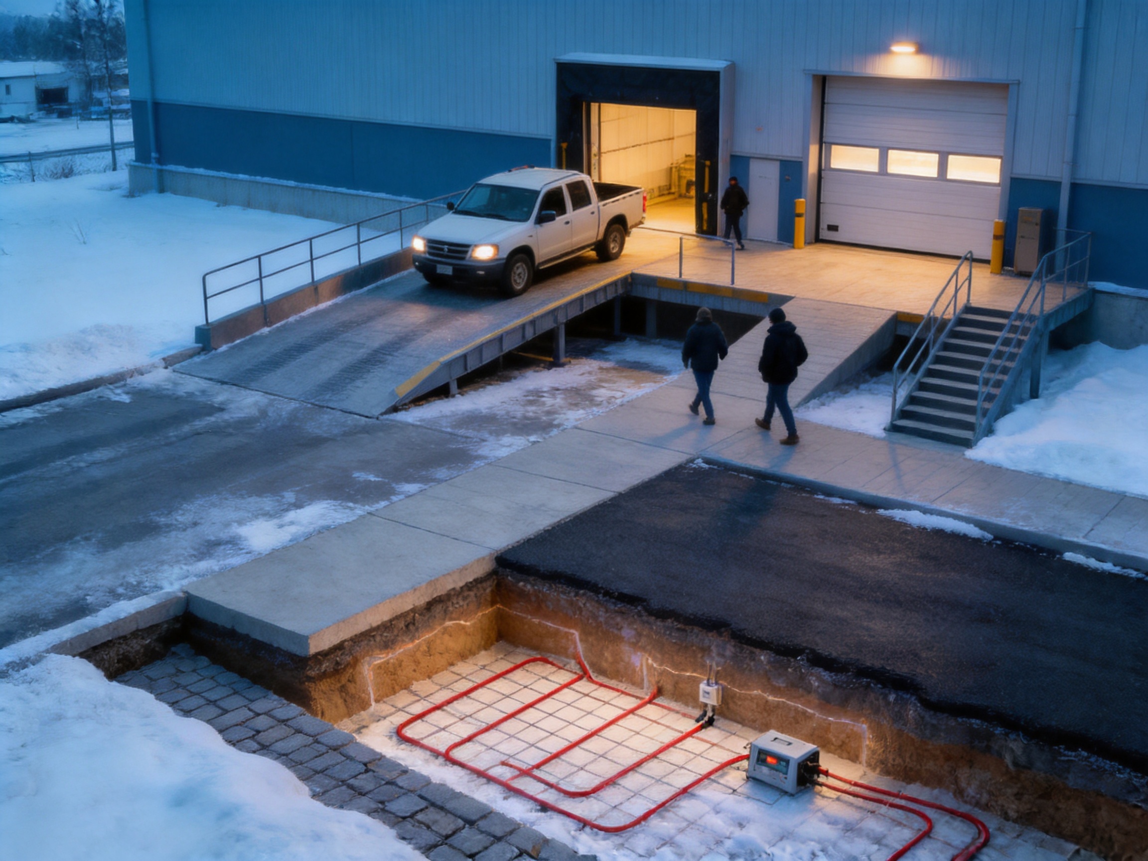
The heating element must be manufactured with controlled resistance and stable electrical characteristics. Variations in conductor dimensions, material composition, or processing can affect the output of the finished cable. Manufacturing control begins with the selection and preparation of suitable conductive materials.
For self-regulating products, the heating component must respond consistently to temperature changes. The relationship between temperature and power output is influenced by the design of the heating matrix, conductive materials, insulation, and surrounding construction. Process consistency is therefore important for predictable field performance.
Snow melting cables are installed in wet and mechanically demanding environments. The insulation system must protect the electrical components from moisture and provide appropriate resistance to heat, abrasion, and construction stress. Protective outer layers help shield the internal structure during handling and installation.
Layer thickness, concentricity, bonding, and surface condition should be controlled during production. Inadequate insulation can increase leakage current or reduce service life, while inconsistent outer dimensions can make installation more difficult.
Factory-prepared connection units can improve repeatability. Instead of making every connection under variable field conditions, the manufacturer can use controlled equipment, defined procedures, and inspection checkpoints. The result is a more consistent connection assembly and a simpler installation process.
Factory assembly may include conductor preparation, sealing, insulation, mechanical reinforcement, labeling, and electrical testing. Each step should be documented through the company’s quality system so that nonconforming assemblies can be identified before shipment.
Finished heating cables should undergo electrical testing appropriate to their design. This may include resistance measurement, insulation resistance testing, dielectric testing where applicable, dimensional inspection, and visual examination. Products intended for integrated control systems may also require functional verification of associated sensors or termination components.
Testing is especially important for long cables because a small defect can affect a large installation. Reliable factory testing reduces the risk that a problem will remain hidden until after the product has been embedded beneath concrete or asphalt.
Professional projects benefit from clear product identification and documentation. Cable length, production batch, electrical data, termination information, test results, installation instructions, and warranty conditions should be available for project records. Traceability supports quality control, maintenance planning, and future troubleshooting.
For large or critical installations, the project owner should retain drawings showing cable routes, joints, sensor locations, circuit numbers, and control panel connections. This documentation can be valuable if the surface is later repaired or modified.
Energy efficiency is one of the main reasons to select a self-regulating snow melting system with intelligent control. The system does not need to operate at full output throughout the entire winter season. It can remain inactive during dry conditions and respond when the combination of moisture and temperature indicates a risk of snow or ice.
The most effective energy strategy usually combines several measures:
• Selecting an appropriate heated area rather than heating the entire site unnecessarily
• Dividing large areas into independently controlled zones
• Using accurate and well-positioned sensors
• Setting suitable activation and deactivation conditions
• Applying self-regulating cable technology
• Maintaining the control panel and sensors
• Inspecting the surface drainage system
• Recording operating performance during winter seasons
The lifecycle value of a snow melting system includes more than electricity consumption. It may also include reduced labor for snow removal, fewer deliveries interrupted by blocked access, lower use of chemical deicers, reduced risk of slips and vehicle accidents, and greater availability of critical routes.
However, an electrically heated surface should not be specified solely on the basis of an estimated energy saving. The project team should compare the complete cost of ownership, including installation, electrical infrastructure, controls, maintenance, repairs, and expected service life.
| System approach | Typical operating principle | Main limitation | Potential advantage of the SANTO solution |
|---|---|---|---|
| Manual snow removal | Workers or equipment remove snow after accumulation | Requires labor, response time, and repeated site access | Automatic heating can reduce accumulation and improve continuous access |
| Chemical deicing | Salt or chemical products lower the freezing point | May cause corrosion, surface damage, or environmental concerns | Electric heating can reduce dependence on chemical treatment |
| Temperature-only heating | Heating starts below a preset temperature | May operate during cold, dry periods | Moisture and temperature sensing can target actual icing conditions |
| Fixed-output heating cable | Produces a relatively constant output when energized | Less adaptable to local temperature changes | Self-regulating output can respond to changing conditions along the cable |
| Prefabricated heating mats | Factory-spaced heating elements cover standard areas | May be difficult to fit around irregular boundaries | Flexible cable layout can accommodate complex shapes |
This comparison is intended as a general guide. The best solution depends on the climate, area size, safety requirements, construction type, and available maintenance resources. In many projects, a combined approach may be appropriate, with electric snow melting used in high-risk areas and manual or chemical methods used elsewhere.
The SANTO UFP product can provide practical benefits during project design and installation. Its flexible form allows engineering teams to create layouts that follow the actual surface instead of relying only on standard rectangular modules. This can simplify the treatment of irregular areas and reduce the need for unused heated sections.
Factory-supplied tail-end connection units can also help contractors organize installation work. Clear termination arrangements can reduce field assembly time and support more consistent quality. When cable lengths can be selected or prepared for the project, the installation team may be able to reduce excess cable, simplify circuit identification, and improve the accuracy of as-built documentation.
The product range offered by the manufacturer also supports system integration. In addition to snow melting cables, the company manufactures other electric heating products and accessories. This enables distributors and engineering partners to source related heating components from a company with experience across several application categories.
For original equipment manufacturers and project developers, the company also describes itself as an OEM and ODM supplier. Customization may be relevant when a project requires particular cable lengths, connection arrangements, packaging, labels, control panel configurations, or application-specific documentation. Any customized design should be reviewed and approved through the appropriate engineering and quality procedures.
A complete snow melting installation requires more than heating cable and sensors. The control panel should be designed to distribute power safely, protect circuits, provide clear status information, and allow authorized personnel to inspect or service the system.
Electrical protection may include circuit breakers, residual current protection, contactors, terminal blocks, surge protection, grounding provisions, and control relays. The exact configuration depends on local electrical codes, supply voltage, circuit size, installation environment, and project specifications.
The control panel should be located in a suitable accessible area protected from unnecessary moisture, impact, and unauthorized operation. Labels should identify each heating zone, sensor input, circuit, and protective device. For larger systems, remote alarms or building management system connections may be considered.
The controller should be commissioned after the sensors and heating circuits have been installed. Commissioning should verify that the system starts under the intended environmental conditions, remains off when the surface is cold but dry, and stops or reduces operation when the snow or moisture condition has cleared.
Sensor placement has a direct influence on control performance. A sensor installed in a location that does not represent the treated surface may cause premature activation or delayed response. The design should consider shading, wind exposure, drainage, snow accumulation, traffic, and the proximity of walls or heat sources.
Ground temperature and moisture sensors should be placed where they can detect the condition that the system is intended to control. Ambient temperature sensors should be protected from direct heat sources and installed according to the controller manufacturer’s instructions.
Commissioning should include the following general steps:
• Confirm that the installation matches the approved drawings
• Verify cable resistance and insulation condition
• Check all connection units and circuit labels
• Confirm sensor wiring and sensor location
• Test the control panel and protective devices
• Simulate or observe suitable temperature and moisture conditions
• Confirm the response of each heating zone
• Record the final test results
System operators should receive instructions explaining normal operation, alarm conditions, manual override functions, inspection intervals, and emergency shutdown procedures. A technically advanced cable cannot compensate for poor commissioning or incorrect control settings.
Once installed beneath a finished surface, a snow melting cable may be difficult and expensive to access. Reliability must therefore be considered from the design stage. Correct cable selection, proper installation depth, adequate mechanical protection, careful termination, and complete testing are essential.
Routine maintenance is generally focused on the control equipment, sensors, electrical protection, and surface condition. Operators should inspect the control panel before the winter season, check for alarms, verify sensor operation, and confirm that circuit protection remains functional.
Drainage should also be maintained. A blocked drain can allow meltwater to accumulate and refreeze even when the heating system is functioning. Cracks, surface repairs, construction changes, and new landscaping should be reviewed to ensure that they do not damage the cable or alter water flow.
If a fault is suspected, the affected circuit should be isolated and tested by qualified personnel. Repairs should use approved components and procedures. Surface excavation should not begin until cable routes and test results have been reviewed.
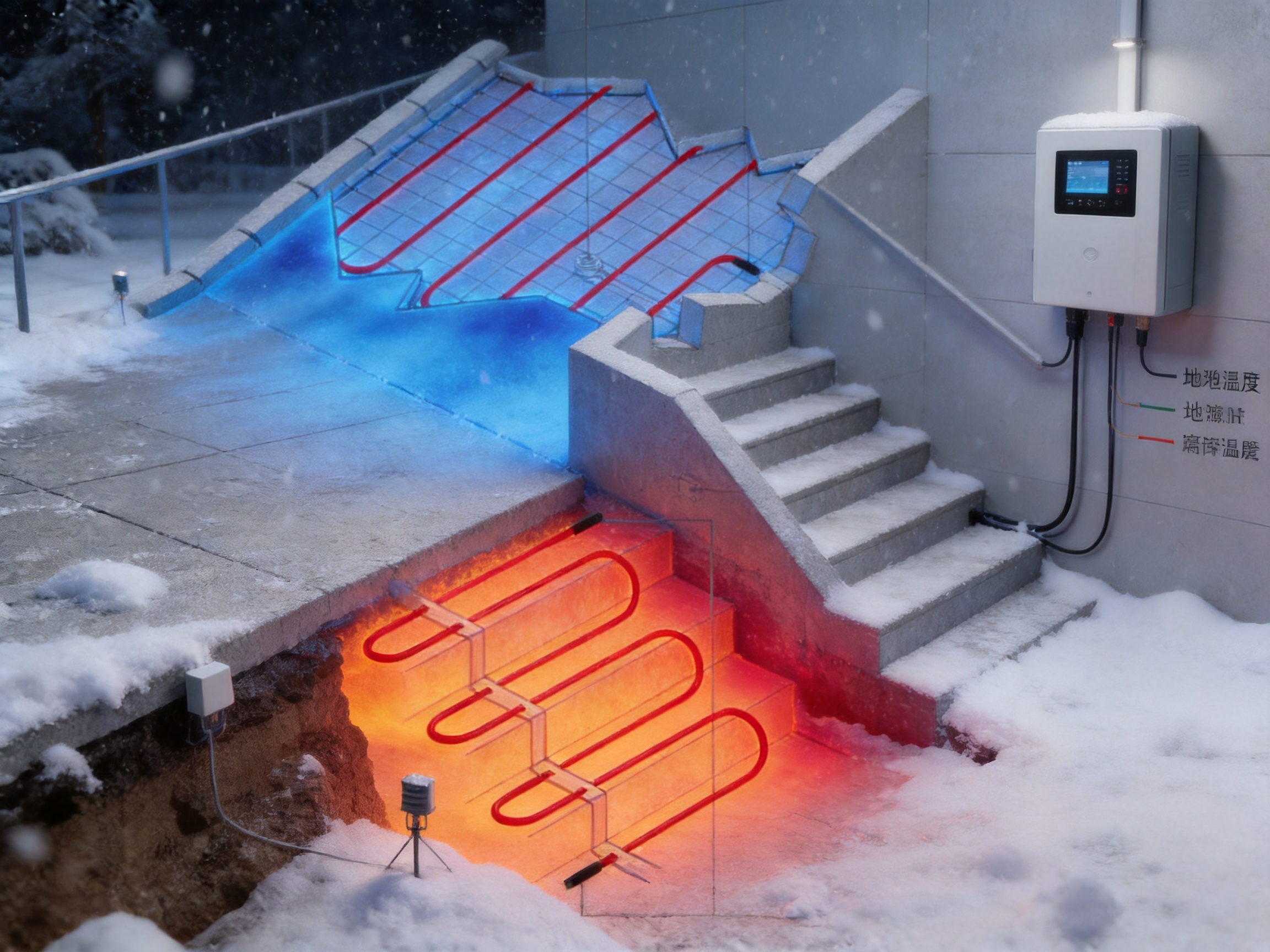
Snow melting systems can contribute to safer winter access and may reduce the use of salt and other chemical deicers. This can be beneficial in areas where corrosion, vegetation damage, concrete deterioration, or runoff quality is a concern.
Electric heating also requires responsible energy management. The most environmentally appropriate design is not necessarily the one with the highest installed power. It is the design that provides the required safety performance with suitable zoning, intelligent control, efficient operation, and proper maintenance.
Electrical safety must remain a priority. The system should be designed, installed, tested, and maintained according to applicable national and local regulations. Grounding, residual current protection, insulation integrity, and safe access to control equipment should be addressed by qualified professionals.
Before ordering a snow melting cable system, project teams should confirm the following information:
• Exact dimensions and shape of each heated zone
• Surface material and installation method
• Required snow melting or ice prevention performance
• Local temperature and snowfall conditions
• Available electrical supply
• Required circuit division and control zones
• Sensor quantity and locations
• Cable length and termination requirements
• Compatibility of the control unit and accessories
• Construction schedule and paving procedure
• Testing and documentation requirements
• Maintenance access and future repair strategy
• Certification and regulatory requirements
Providing this information early allows the manufacturer, distributor, and engineering contractor to develop a more accurate proposal. It also reduces the risk of selecting an unsuitable cable length, power rating, termination arrangement, or control configuration.
Snow melting is a specialized application because the product is embedded in a structural surface and must operate in wet, cold, and mechanically demanding conditions. Experience in general electrical manufacturing is useful, but experience with electric heating products, temperature control, insulation systems, and field installation requirements is particularly important.
SANTO brings more than 35 years of industry experience to this product category. Its manufacturing scope includes self-regulating heating belts, constant-power heating cables, silicone rubber heating products, glass fiber heating products, MI cables, snow melting cables, and associated accessories. This broad portfolio suggests that the company can support different heating requirements rather than relying on a single technology for every application.
The company’s reported ISO9001 quality system, CCC certification, research activities, irradiation center, product development history, distributor network, and international market experience are additional factors for buyers to evaluate. Customers should request current technical datasheets, certification documents, testing information, installation instructions, and application references during the procurement process.
For international projects, communication and documentation are also important. A supplier that can provide product identification, wiring information, installation guidance, customized manufacturing support, and after-sales assistance can reduce project risk for contractors and system integrators.
It is used for ground heat tracing, snow melting, and ice prevention beneath roads, ramps, driveways, walkways, steps, loading areas, and other outdoor surfaces. It can be incorporated into concrete, sand or cement beds, and suitable asphalt construction applications.
The cable is designed to adjust its heat output according to temperature conditions along its length. Warmer sections can reduce output, while colder sections can provide comparatively more heat. This helps the cable respond to variable outdoor conditions.
The cable can form part of an automatic system when connected to a suitable control unit. The VIA-DU-20 controller uses temperature and moisture information to determine when snow or ice melting is required. Correct sensor installation and commissioning are necessary for automatic operation.
The supplied product information states that the intelligent control approach can save up to 80 percent compared with standard constant-temperature control. Actual savings depend on weather, surface design, sensor operation, system settings, heated area, and other site conditions. A project-specific calculation should be completed before an energy-saving figure is guaranteed.
The product information indicates that the system can be used directly under asphalt when the installation is designed for that purpose. Asphalt temperature, paving sequence, compaction equipment, cable protection, and manufacturer instructions must be reviewed carefully before installation.
Yes. The flexible cable format allows the heating layout to follow ramps, curved areas, irregular entrances, and complex boundaries more easily than many standard mats. The layout should still be engineered to maintain suitable spacing and avoid prohibited bends or crossings.
The supplied information indicates that certain system cables can be cut as needed and connected at the tail end on site, while factory-supplied tail-end connection units are also available. On-site cutting and termination should only be performed when explicitly permitted for the selected cable and by qualified personnel using approved components.
A complete system may include heating cables, tail-end connection units, sensors, the intelligent control unit, an integrated control panel, electrical protection, wiring accessories, installation materials, and technical documentation. The exact supply should be confirmed in the quotation and project specification.
No. A correctly designed system can reduce snow accumulation and help maintain safer surfaces, but extreme snowfall, power interruptions, drainage problems, or unusual weather may still require manual intervention. Operators should maintain an emergency snow removal plan.
The system is described as suitable for concrete, sand or cement mixtures, and selected asphalt applications. Surface construction, cable depth, installation temperature, mechanical loading, and curing procedures must be addressed in the design.
Sensors should be located where they accurately represent the condition of the treated surface. The design should account for shade, wind, drainage, snow accumulation, walls, heat sources, and traffic. Sensor placement should follow the control unit and project engineering instructions.
Maintenance normally includes seasonal inspection of the control panel, electrical protection, sensors, alarms, connections, and surface drainage. Heating circuits should be tested by qualified personnel if a fault is suspected. Construction or landscaping changes should be reviewed to prevent cable damage.
SANTO describes its business as including OEM and ODM heating cable manufacturing. Depending on technical feasibility and project volume, customization may include cable length, termination, labeling, packaging, control integration, and application-specific documentation.
Useful information includes the heated area dimensions, surface construction, location and climate, snow and ice requirements, electrical supply, preferred control method, installation schedule, cable length, zoning requirements, and any certification or documentation requirements.
The SANTO UFP self-regulating heating and snow melting cable is designed for applications where winter safety, flexible installation, and controlled energy use are important. Its ability to support irregular layouts makes it suitable for ramps, roads, walkways, steps, and other areas that are difficult to treat with standard heating mats.
When combined with the VIA-DU-20 intelligent control unit, the system can use ground temperature, ground humidity, and ambient temperature data to activate heating when moisture and freezing conditions indicate a genuine snow or ice risk. This is a significant advantage over temperature-only control, which may operate unnecessarily during cold but dry periods.
The product’s potential advantages are supported by the manufacturer’s experience in electric heating technology, broad product range, research and development activities, quality management certification, and international supply capability. Nevertheless, the final performance of any snow melting system depends on correct design, cable spacing, sensor placement, electrical protection, installation quality, commissioning, and maintenance.
For contractors, distributors, engineers, and property owners, the best purchasing decision should be based on the complete application rather than on the cable alone. With proper planning and professional installation, a self-regulating snow melting system can become an effective component of a safer, more reliable, and more energy-conscious winter surface management strategy.
1. SANTO Thermal Control Technology Co., Ltd., product information for the UFP self-regulating heating and snow melting cable.
2. SANTO Thermal Control Technology Co., Ltd., technical information for the VIA-DU-20 intelligent snow melting control unit.
3. SANTO Thermal Control Technology Co., Ltd., corporate information, manufacturing capabilities, product development history, and quality certifications.
4. General principles of electric resistance heating cable design and ground heat tracing engineering.
5. General guidance for electrical protection, sensor installation, commissioning, and maintenance of outdoor heating systems.
6. General engineering practices for integrating heating cables into concrete, sand-bed, paving, and asphalt surface assemblies.
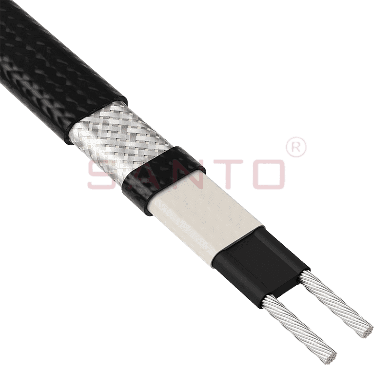
The SANTO UFA range of self-regulating heating cables is mainly used for frost protection of pipes and vessels but can also be used to maintain processes up to 65°C. These heating cables are available...
See Details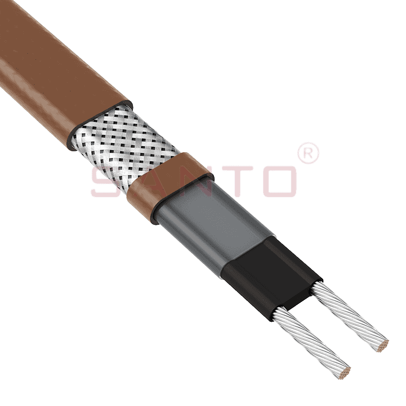
The SANTO UFB range of self-regulating heating cables is mainly used for frost protection of pipes and vessels requiring a higher power output than the UFA heating cables can supply. They can also be ...
See Details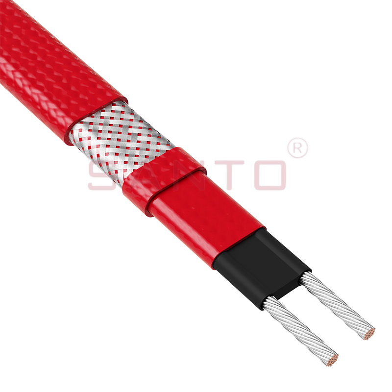
The SANTO UFC range of self-regulating heating cables is used for frost protection of pipes and vessels that require steam cleaning. They can also be used to maintain processes up to 121°C. These heat...
See Details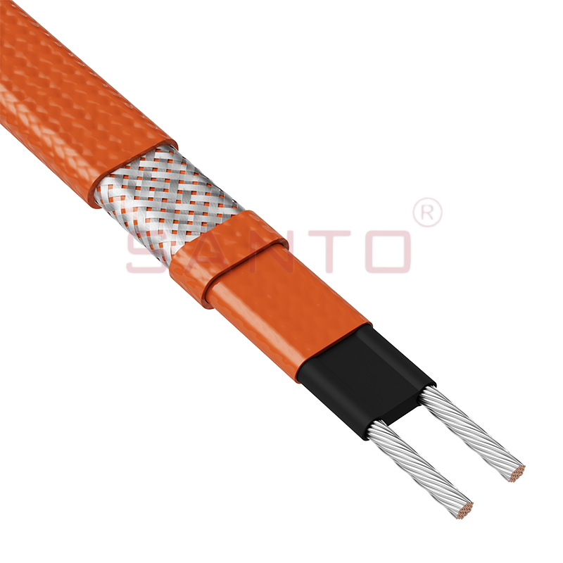
The SANTO UFO range of self-regulating heating cables is mainly used for frost protection of pipes and vessels that require steam cleaning . They can also be used to maintain processes up to 150°C. Th...
See Details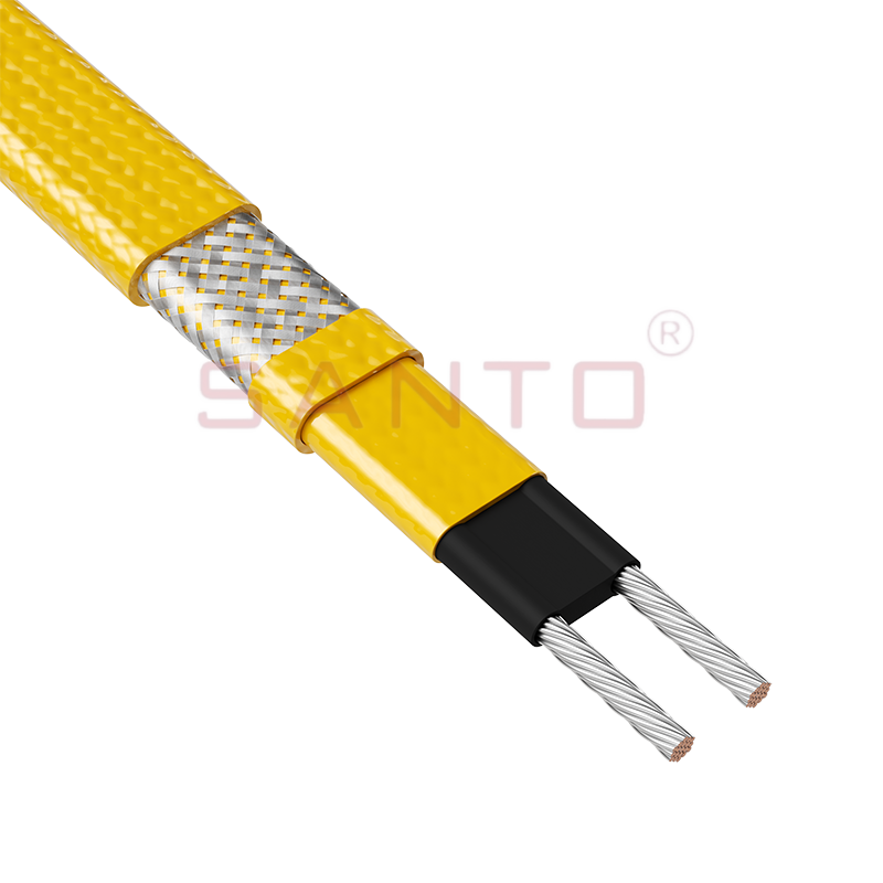
The SANTO UFD series of self-regulating heating cables are mainly used for freeze protection of pipes and vessels, but can also be used to maintain processes up to 200°C. These heating cables are avai...
See Details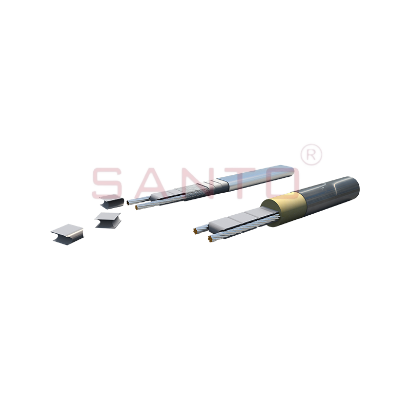
SANTO UFY heating wire is suitable for applications that maintain process temperatures up to 260 ℃ and can be steam blown; The self-regulating and parallel circuit heating wires of the UFY series are ...
See Details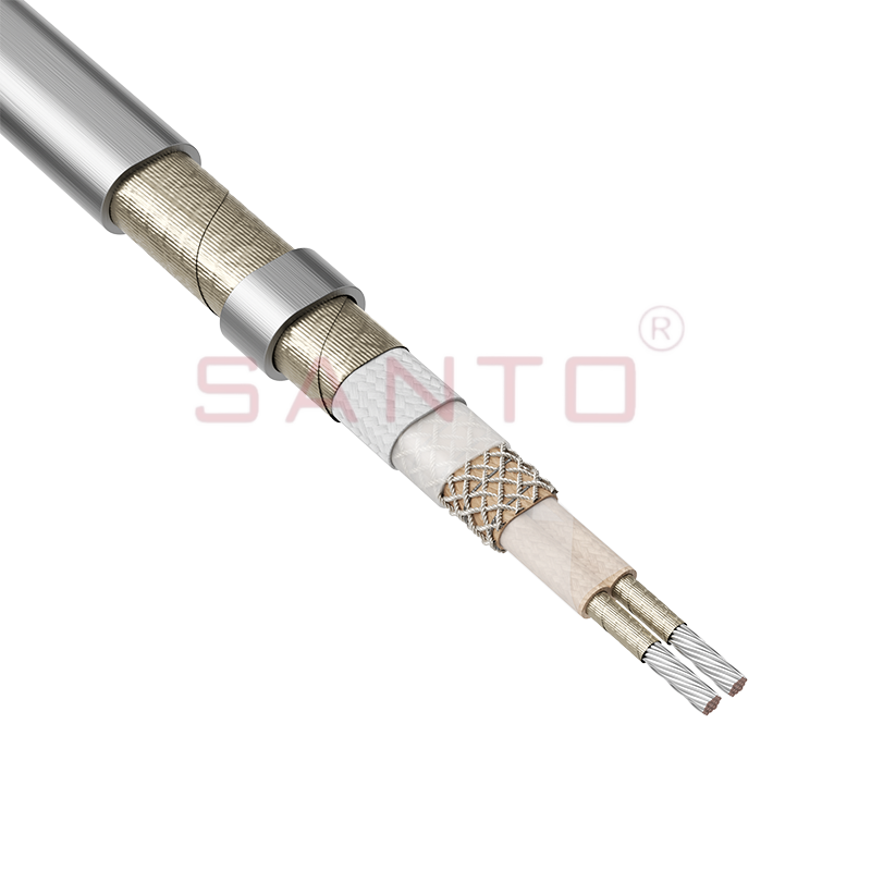
The SANTO UFM series self-regulating heating cables are mainly used for freeze protection of pipes and vessels, but can also be used to maintain processes up to 400°C. These heating cables are availab...
See Details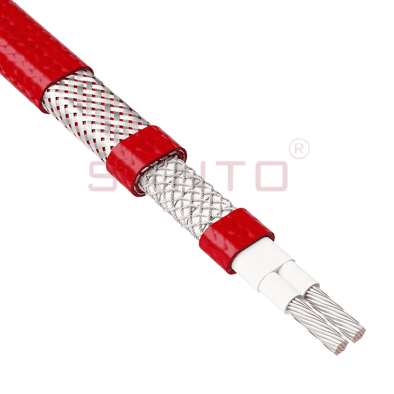
The SANTO ACC range of power-limiting heating cables is mainly used for temperature maintenance of processes and offers the advantage of a high power output at high temperatures which can reduce the n...
See Details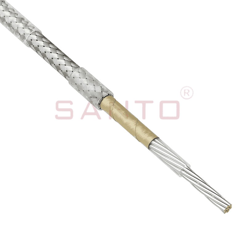
The stranded high temperature conductor is nickel plated to ensure a long life at elevated temperatures in corrosive environments. It is electrically isolated using an innovative sandwich construction...
See Details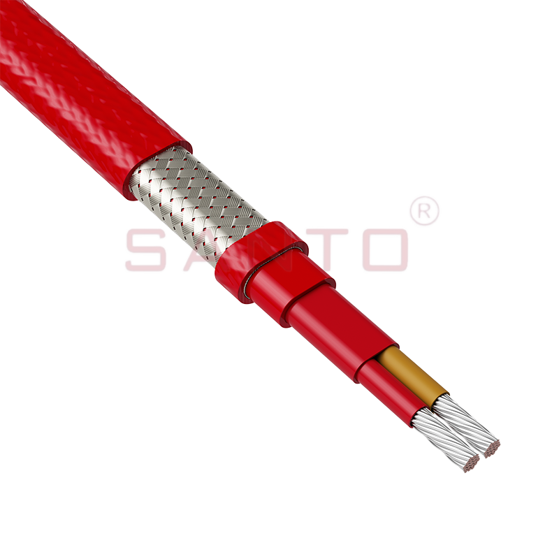
The stranded high temperature conductor is nickel plated to ensure a long life at elevated temperatures in corrosive environments. It is electrically isolated using an innovative sandwich construction...
See Details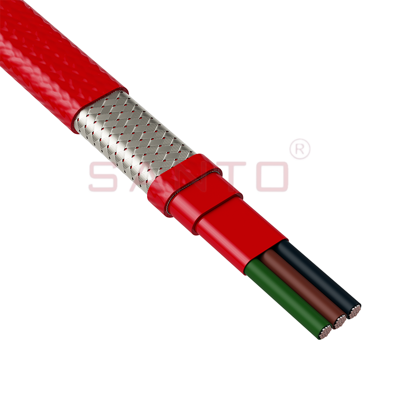
The stranded high temperature conductor is nickel plated to ensure a long life at elevated temperatures in corrosive environments. It is electrically isolated using an innovative sandwich construction...
See Details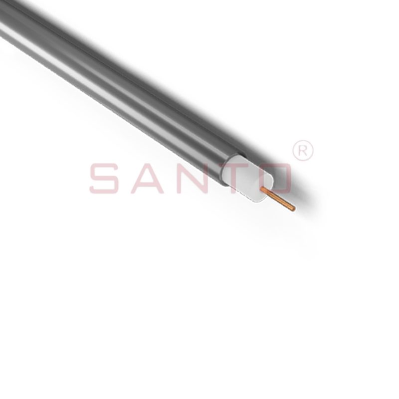
SANTO HAx mineral insulated (MI) Alloy 825 series heating cables are suitable for use in hazardous areas. They have been designed for use in freeze protection and temperature maintenance applications ...
See Details
Santo electric heating strips are widely used in key industries in China.

