 English
 English
 русский
 日本語
 Español
 中文简体

The SANTO UFA range of self-regulating heating cables is mainly used for frost protection of pipes and vessels but can also be used to maintain processes up to 65°C. These heating cables are available...
See Details
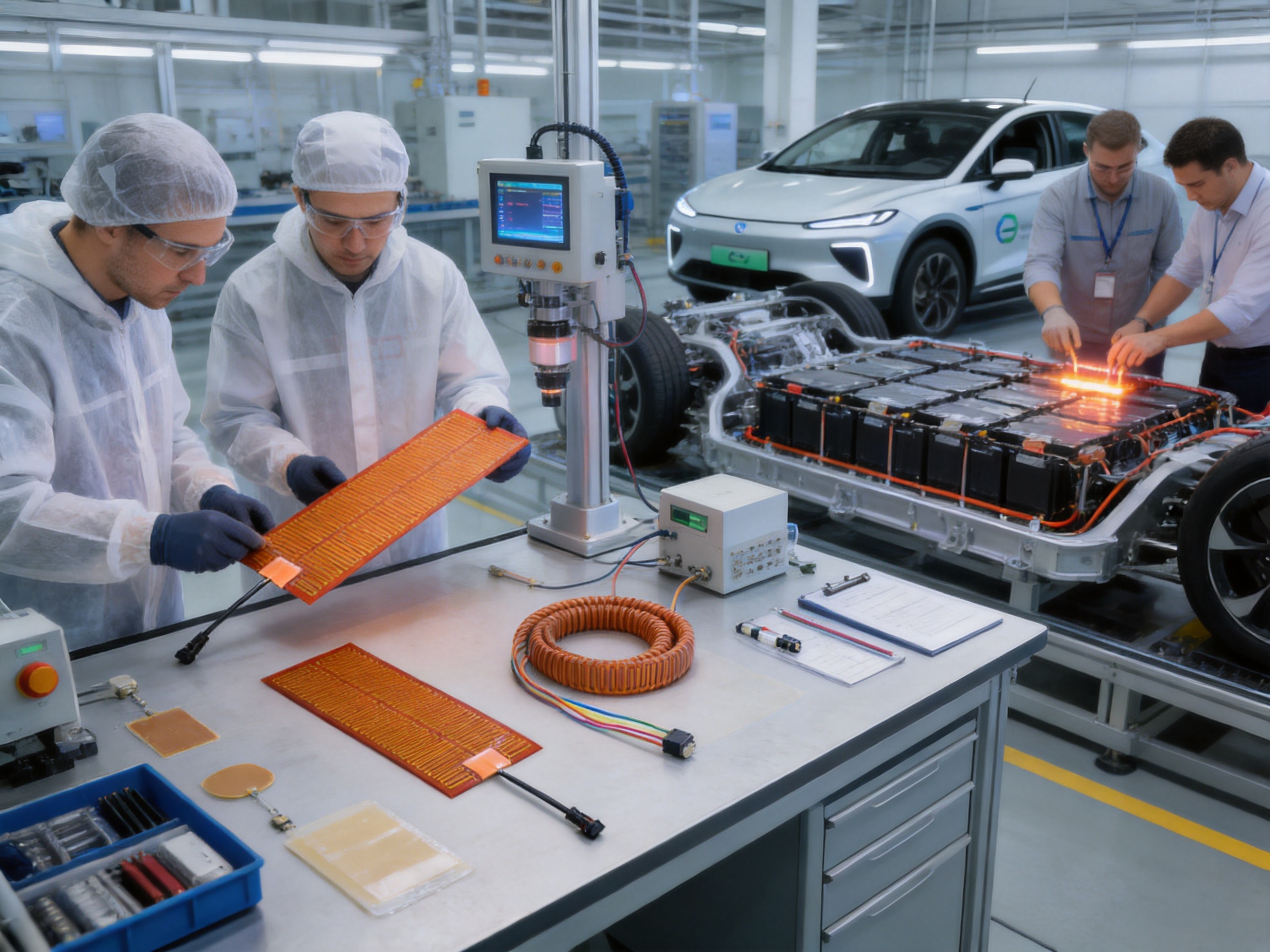
Electric vehicles depend on battery systems that must deliver stable power across a wide range of operating conditions. Among the most challenging conditions is low temperature. Cold weather can reduce battery charging acceptance, slow electrochemical reactions, increase internal resistance, limit available power, and affect driving range. For vehicles operating in winter climates, at high altitudes, or in refrigerated and outdoor environments, an effective battery heating solution is an important part of the thermal management system.
A Kapton car battery heater is a thin, flexible electric heating component designed to provide controlled heat directly to or around a power battery. By raising the battery temperature within a suitable operating range, the heater helps reduce the performance impact caused by cold environments. Its thin construction, flexible form, customizable geometry, and electrical insulation properties make it suitable for applications where space, weight, thermal uniformity, and installation adaptability are important.
The heater described in this article is manufactured for customized new-energy vehicle applications. It can be produced with different materials, sizes, shapes, power ratings, connection arrangements, insulation structures, and control accessories according to battery-pack requirements. The design can also be integrated with wires, adhesive layers, aluminum plates, thermal-conductivity materials, insulation materials, temperature controllers, and sensors.
This article explains the operating principles, construction, technical specifications, advantages, manufacturing capabilities, quality considerations, installation factors, and application value of Kapton battery heaters. It also examines why a customized heater can offer practical advantages over generic heating pads and less adaptable heating technologies.
Content
Battery temperature has a direct influence on electric vehicle performance. Lithium-ion batteries are particularly sensitive to low temperatures because the movement of ions within the cell becomes less efficient as temperature decreases. The result may include reduced discharge power, slower charging, increased charging time, and temporary loss of usable capacity.
When a vehicle is started in cold weather, the battery may not be able to deliver its normal output immediately. The vehicle control system may limit acceleration or regenerative braking until the battery reaches a more suitable temperature. During charging, the battery management system may also reduce the charging current to protect the cells from undesirable low-temperature charging conditions.
A battery heater provides a controlled source of thermal energy. It can be activated during preheating, charging, vehicle startup, or operation, depending on the control strategy. When paired with a temperature sensor and controller, the heater can support a more stable battery temperature without relying only on waste heat from other vehicle systems.
For commercial vehicles, buses, utility vehicles, delivery fleets, and passenger cars used in winter regions, reliable battery heating can improve vehicle availability. It can also help reduce the difference between expected and actual range during cold-weather use. The heater does not replace a complete battery thermal management system, but it can serve as an important heating element within that system.
A Kapton car battery heater is a flexible electric resistance heater constructed with a thin polyimide-based insulating film commonly known as Kapton. The resistance heating element is arranged in a controlled pattern between insulating layers. When electrical power is applied, the resistance element generates heat, which is transferred through the heater surface to the battery pack, mounting plate, thermal interface layer, or surrounding structure.
Polyimide film is valued in heating applications because it is thin, lightweight, electrically insulating, and capable of operating across a broad temperature range. Its flexibility allows the heater to conform to flat or slightly contoured surfaces. This is useful when a battery pack contains limited installation space or when the heating surface must follow the shape of a module, enclosure, or metal plate.
The heater can be designed as a single-zone or multi-zone component. A single-zone heater provides a uniform heating area with one electrical circuit. A multi-zone design may divide the heating surface into separate sections, allowing more precise control for battery packs with different thermal requirements.
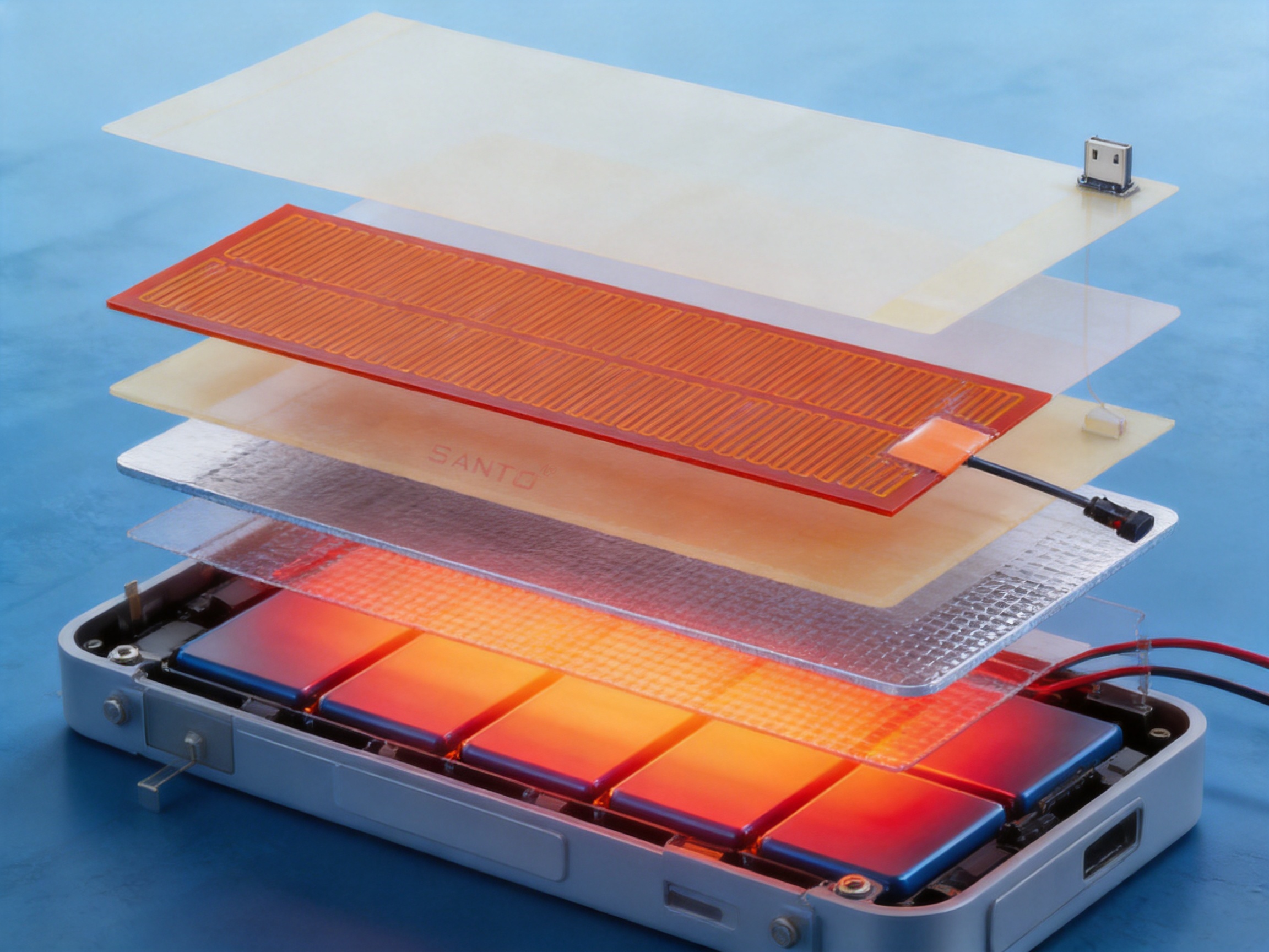
Depending on the application, the heater may include a pressure-sensitive adhesive layer, aluminum heat-spreading plate, thermal interface material, insulating backing, protective cover, sensor pocket, or mechanical fastening points. These options enable the heater to be adapted to different battery pack structures and installation methods.
The available product specification provides a minimum thickness of 0.15 millimeters. This thin profile helps reduce the space required for integration and can simplify installation in compact battery compartments. The actual finished thickness may vary according to the selected insulation, adhesive, heat-spreading layer, protective structure, and wiring requirements.
The specified heating temperature is no more than 180 degrees Celsius. This value represents the heater’s applicable upper heating-temperature limit under the defined design conditions. It should not be interpreted as the recommended operating temperature of a battery cell. Lithium-ion battery packs must be controlled according to their cell chemistry, battery management system, pack construction, and safety requirements.
The specified power density is no more than 3 watts per square centimeter. Power density should be selected according to the battery pack size, heating target, thermal resistance between the heater and battery, ambient temperature, available voltage, required preheating time, and permitted surface temperature.
The insulation resistance is specified as at least 100 megaohms at 1,000 volts. High insulation resistance helps separate the electrical heating circuit from the battery enclosure and other conductive components. Insulation performance must be verified using suitable test procedures and should be considered together with dielectric strength, grounding, creepage distance, mechanical protection, and environmental exposure.
| Specification | Available Requirement | Application Significance |
|---|---|---|
| Minimum thickness | 0.15 mm or greater | Supports low-profile installation in compact battery spaces |
| Heating temperature | Up to 180 °C | Provides a defined upper design temperature for the heater structure |
| Power density | Up to 3 W/cm² | Allows the heating output to be matched with the thermal design |
| Insulation resistance | At least 100 MΩ at 1,000 V | Supports electrical separation and insulation reliability |
| Product configuration | Customized | Enables adaptation to pack dimensions, voltage, shape, and control requirements |
| Optional accessories | Wires, adhesive, aluminum plate, thermal materials, insulation, controller, sensor | Supports a complete application-specific heating assembly |
These values provide a starting point for engineering discussion rather than a universal configuration for every vehicle. A battery heater should be specified after the battery pack manufacturer, vehicle integrator, or thermal management engineer has defined the required operating conditions.
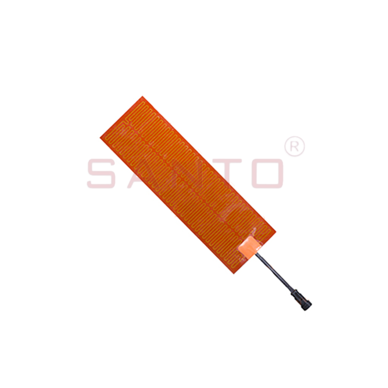
KAPTON car battery heater
The heater’s fundamental function is to convert electrical energy into controlled thermal energy. The resistance element is selected and arranged to produce the required output at the designated supply voltage. Heat then moves through the insulating and interface layers and into the battery module, pack enclosure, or thermal spreader.
In a typical electric vehicle application, the vehicle control system monitors battery temperature through one or more sensors. If the temperature is below the permitted charging or performance range, the controller activates the heater. As the battery approaches the target temperature, the controller can reduce or stop the heating power.
Heating may be performed before charging to improve charging acceptance. It may also be used before vehicle operation so the battery can provide more consistent power from the beginning of a journey. In some systems, heating is managed in stages, with a higher initial output followed by lower holding power.
The heater can be installed beneath the battery pack, between a battery enclosure and a thermal spreader, beside a module, or in another position approved by the pack designer. The installation location must ensure adequate thermal contact while avoiding damage to cells, busbars, connectors, seals, and sensitive electronic components.
Battery packs are highly space-constrained assemblies. Additional components must be integrated without unnecessarily increasing pack size or weight. A thin Kapton heater can be placed in areas where a bulky cartridge heater, tubular heater, or thick silicone heating panel may be difficult to install.
The low-profile structure may also reduce the distance between the heating element and the target surface. A shorter thermal path can support more responsive heat transfer, provided that the heater is correctly bonded or mechanically installed and that an appropriate thermal interface material is used.
Battery packs are not always simple rectangular structures. They may include stepped surfaces, recesses, mounting channels, module partitions, and service openings. Flexible polyimide film can be cut and formed to suit many custom layouts.
Custom shapes may include rectangular, circular, ring-shaped, strip-shaped, irregular, or multi-section patterns. Openings can be incorporated around fasteners, connectors, locating pins, or other features. This adaptability can improve coverage and reduce unused heating areas.
The insulating film separates the resistance circuit from the battery enclosure and adjacent conductive parts. The stated insulation resistance requirement of at least 100 megaohms at 1,000 volts provides an important electrical performance benchmark.
High insulation resistance is especially important in high-voltage vehicle systems. It helps reduce leakage-current risk and supports the overall electrical safety strategy. However, the heater must still be installed in accordance with the vehicle’s high-voltage protection requirements, grounding system, creepage and clearance design, and environmental sealing specifications.
The resistance pattern can be designed to distribute heat across the specified surface. Compared with a single concentrated heat source, a properly designed flexible heater can reduce localized hot spots and provide more even thermal coverage.
Uniformity depends on several factors, including resistance layout, power density, thermal contact, surface flatness, battery material, insulation thickness, ambient airflow, and the presence of heat-spreading plates. For demanding applications, thermal simulation and temperature mapping can be used to refine the heater design.
A major advantage of a customized Kapton heater is the ability to match the product to the battery rather than forcing the battery to fit a standard heater. The design can be adapted to required length, width, shape, power, voltage, lead position, sensor location, adhesive selection, and insulation construction.
This is valuable for original equipment manufacturers, battery pack developers, fleet vehicle manufacturers, and engineering teams working with several battery platforms. A customized design can support more efficient production integration and reduce the need for improvised mounting solutions.
Different electric vehicle platforms may use coolant heaters, resistive heating plates, flexible silicone heaters, cartridge heaters, or other thermal technologies. Each approach has a suitable application area. The most appropriate choice depends on the battery architecture, available space, energy source, target temperature, and control method.
| Heating Method | Typical Strength | Potential Limitation | Where a Kapton Heater Can Help |
|---|---|---|---|
| Coolant-based heating | Can heat several areas through a circulating thermal loop | Requires pump, hoses, coolant, valves, and additional space | Provides direct electrical heating without a complete fluid circuit |
| Cartridge or tubular heater | Robust point or line heating | May require mounting hardware and more installation space | Offers a thin surface-mounted solution for distributed heating |
| Metal heating plate | Good mechanical strength and heat spreading | Can add weight and limit flexibility | Can combine a flexible heater with an optional aluminum plate |
| Silicone rubber heater | Flexible and suitable for many industrial surfaces | May be thicker in certain configurations | Provides a lower-profile polyimide option where thickness is critical |
| Generic heating pad | Simple procurement and standard availability | May not match battery shape, voltage, lead position, or control needs | Provides application-specific customization and integration options |
The comparison does not mean that one technology is universally superior. Instead, it shows how a Kapton heater can be advantageous when compactness, low weight, flexibility, electrical insulation, and customized geometry are priorities.
The heater can be customized according to the electrical requirements of the vehicle or battery pack. Voltage, resistance, power, current, and heating area must be calculated together. A heater designed for a low-voltage auxiliary circuit will have different resistance and wiring requirements from a heater connected to a dedicated high-voltage supply.
Heating area is another important variable. A small module heater may require a compact element with concentrated output, while a large pack heater may use several sections to improve temperature uniformity. Multiple heaters can be connected in parallel or series when permitted by the electrical design.
Lead-wire selection can be matched to the installation environment. Options may include different conductor sizes, insulation materials, lengths, terminal styles, connectors, strain reliefs, and exit directions. The lead exit should be positioned so that it does not interfere with the battery cover, service access, cooling channels, or high-voltage components.
An adhesive layer can simplify installation and improve contact between the heater and the target surface. The adhesive must be selected according to temperature, surface energy, vibration, humidity, chemical exposure, removability, and expected service life. In some designs, a mechanically retained heater may be preferred over permanent bonding.
An aluminum plate can be added to improve heat spreading and mechanical protection. Aluminum conducts heat efficiently and can help distribute energy over a wider surface. It may also provide a convenient mounting interface. The additional mass, thickness, corrosion protection, and thermal expansion must be considered during the design process.
Thermal-conductivity materials can be placed between the heater and battery enclosure to reduce contact resistance. Insulation materials can be added on the opposite side to direct more heat toward the battery and reduce unwanted heat loss. These layers should be selected as part of a complete thermal stack rather than as isolated accessories.
Temperature controllers and sensors can be supplied for applications requiring independent regulation. A sensor may be positioned near the heater surface, on the battery enclosure, or at another representative measurement location. The sensor location must reflect the actual control objective and should be validated through testing.
Manufacturing begins with an application review. The engineering team evaluates the battery dimensions, available installation area, desired heating temperature, supply voltage, power target, preheating time, control method, environmental conditions, and expected service life.
Product drawings may define the heater outline, active heating zone, non-heating zones, mounting holes, lead exits, sensor positions, adhesive boundaries, and insulation requirements. The design may be revised after thermal analysis, prototype testing, or vehicle-level integration.
The resistance element is designed to produce the required electrical output across the specified heating area. Resistance value is related to voltage and power, while the conductor pattern determines how heat is distributed. The spacing, width, routing, and turning points of the resistance path must be controlled to reduce uneven heating.
Designers also consider electrical stress, bending requirements, connection points, and the possibility of localized temperature increases. The active area must remain clear of locations where folding, drilling, cutting, or severe mechanical pressure may occur.
Material selection includes the polyimide insulating film, resistance element, bonding materials, lead wires, terminal components, protective layers, adhesive, thermal interface materials, and optional metal plates. Each material must be compatible with the expected temperature, voltage, humidity, vibration, and chemical environment.
The company manufactures a broad range of electric heating products, including self-limiting heating belts, constant-power heating belts, silicone rubber heaters, glass fiber heating products, mineral-insulated cables, snow-melting cables, and related accessories. This wider product background supports cross-application material and process knowledge.
During assembly, the resistance element is positioned between insulating layers according to the approved design. The layers are bonded or laminated to form a stable heating structure. Alignment is important because displacement can affect heating distribution, thickness, lead connection, and insulation performance.
Where an adhesive backing is specified, the adhesive layer is applied with controlled coverage and protected until installation. Where an aluminum plate or thermal interface layer is included, the additional component is aligned with the active area and secured using the defined assembly method.
Lead wires are attached to the heating element using a connection method appropriate to the design. The connection must provide low electrical resistance, mechanical stability, and reliable insulation. Strain relief may be added to prevent repeated bending from transferring stress to the electrical joint.
Lead length and exit direction are controlled according to the customer’s installation drawing. Connector selection should consider voltage rating, current rating, sealing, vibration, temperature, service access, and compatibility with the vehicle harness.
Inspection may include visual examination, dimensional measurement, resistance testing, insulation resistance testing, dielectric withstand testing, continuity verification, and functional heating tests. The exact test plan should be determined by the product design and customer quality agreement.
Insulation resistance testing at 1,000 volts is particularly relevant to the stated technical specification. The test confirms that the insulating structure maintains a high level of electrical separation under the specified test condition. Results should be documented and evaluated against approved acceptance criteria.
Functional heating tests can verify power output, temperature rise, heating uniformity, and sensor response. Thermal imaging or temperature mapping may be used to identify abnormal hot spots. Dimensional and visual inspections help confirm that the product matches the approved drawing.
The manufacturer states that it has passed ISO 9001 quality system certification and that its products have obtained national CCC certification. Certification status should always be confirmed for the specific product, production site, and intended market before procurement.
The company reports more than 35 years of industry experience, annual output exceeding 10,000 units, more than 2,000 distributors, and business coverage in more than 85 areas. These figures indicate an established operating base in electric heating product development and manufacturing.
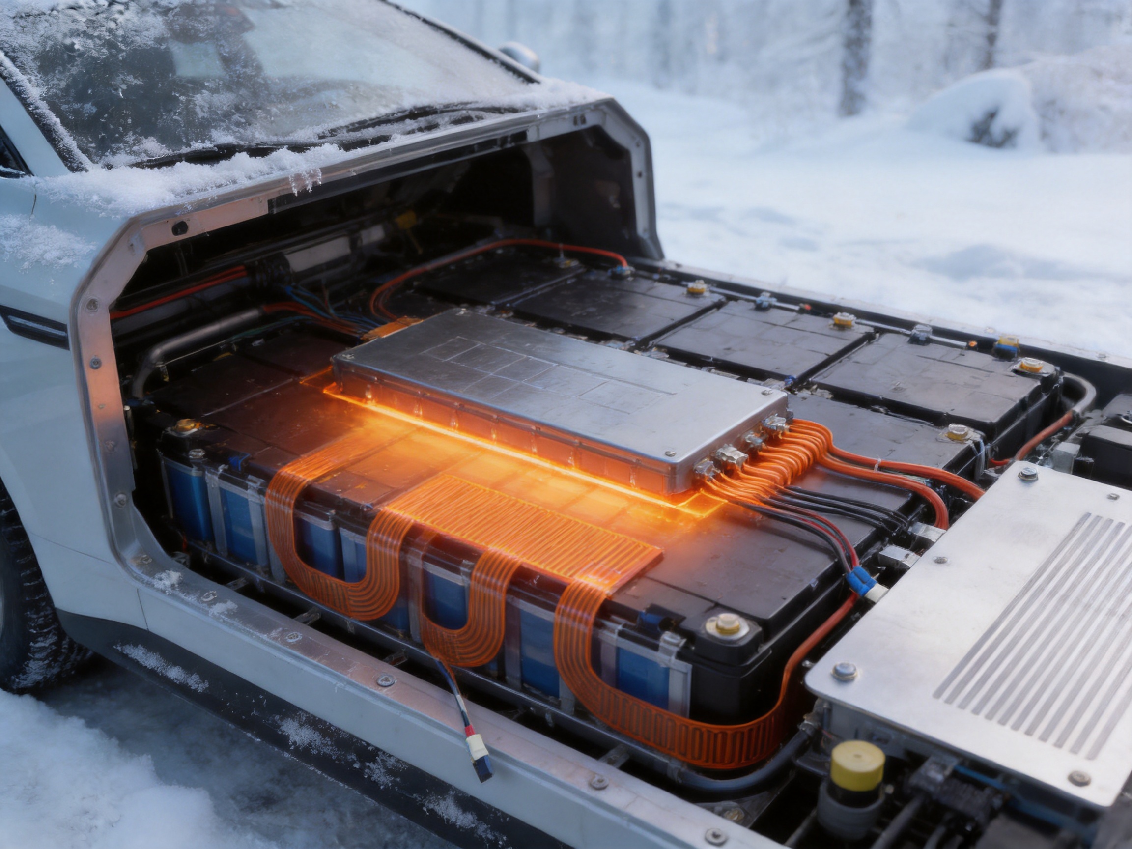
Santo Thermal Control Technology Co., Ltd. is based in Jiangsu Province, an area associated with China’s electric heating belt industry. The company combines research, design, manufacturing, and sales across a broad range of electric heating products.
Its product experience covers automatic temperature-control heating belts, self-limiting heating belts, constant-power heating belts, glass fiber heating belts, silicone rubber heating products, mineral-insulated cables, snow-melting cables, electric hot wires, LCD-tracked heaters, and accessories. This product diversity is relevant because battery heaters often require knowledge from several heating disciplines rather than a single standardized process.
The company states that it cooperates in product research with Harvard University in the United States. It also reports the establishment of an irradiation center in 2013, the invention of a self-limiting temperature nano far-infrared heater in 2014, the development of a carbon fiber parallel heating cable in 2017, and the construction of a product simulation testing laboratory following additional factory expansion.
In 2023, the company established a factory in Russia to expand its international business presence. Its reported history also includes explosion-proof certification and EAC Eurasian Union certification for relevant products. These milestones demonstrate experience in developing heating products for different technical and market environments, although project-specific compliance must be verified separately.
Vehicle and battery manufacturers often need components that can be integrated into a defined assembly process. A customized heater can be supplied with drawing-controlled dimensions, specified lead exits, selected adhesive systems, and packaging that protects the product during transportation and installation.
The ability to coordinate heater design with battery geometry can reduce the need for field modifications. It may also help the engineering team manage the thermal interface more systematically. Instead of selecting a generic pad and adapting the battery structure around it, the heater can be developed as part of the battery pack architecture.
For products manufactured in multiple vehicle models, a modular approach may be possible. A basic heating technology can be adapted into different shapes or power ratings while retaining common control and quality principles. This can simplify technology transfer and support platform-based product development.
OEM customers may also benefit from technical discussion during the design stage. Questions about heating time, electrical input, sensor position, surface temperature, adhesive selection, environmental exposure, and packaging can be addressed before mass production begins.
Commercial vehicles may operate on fixed schedules and cannot always remain idle during cold weather. A battery heater can support more predictable startup and charging behavior for delivery vans, buses, service vehicles, and specialized electric transport equipment.
Fleet operators may use preheating during scheduled charging. The vehicle can use external electrical power to warm the battery before departure, reducing the need to draw heating energy from the traction battery while driving. This strategy may help preserve usable driving energy in cold conditions.
For vehicles operating in different regions, the heater control system can be adjusted according to ambient temperature and duty cycle. A vehicle used in a moderate climate may require less heating power than one operating in severe winter conditions. Customized heater output allows the thermal system to be matched to the actual operating environment.
The heater should be installed only according to an approved engineering procedure. The target surface must be clean, dry, smooth, and free from contaminants that could reduce thermal contact or weaken adhesive bonding. Sharp edges and protrusions should be avoided or protected.
The heater must not be folded, sharply creased, punctured, cut, or compressed beyond its design limits. Damage to the insulating layers or resistance pattern can create electrical and thermal hazards. The minimum bending radius, if applicable, should be defined in the product drawing.
Thermal contact is essential. Air gaps can significantly reduce heat transfer and create local temperature differences. If a thermal interface material is used, its thickness and compression should be controlled. Excessive interface thickness may increase thermal resistance, while insufficient coverage may produce uneven contact.
The heater should be positioned away from areas exposed to direct mechanical impact, fluid accumulation, high-voltage terminals, moving components, and service tools. Lead wires should be routed with adequate protection against abrasion, vibration, and repeated movement.
Installation into a battery pack must be coordinated with the battery management system. The control logic should define when heating is allowed, the temperature range, maximum heating duration, fault response, and interaction with charging. Over-temperature protection and electrical fault monitoring should be included in the overall vehicle design.
A battery heater is an electrical component installed near high-energy storage equipment. Safety must therefore be considered at the product, pack, vehicle, and system levels. The heater design should prevent unintended contact between the resistance element and conductive battery structures.
Temperature limits must be established for the heater surface, adhesive, insulation, enclosure, battery cells, and adjacent components. The maximum heater temperature is not necessarily the correct battery temperature. A control system should use representative sensor data and include safeguards against sensor failure or abnormal heating.
Reliability testing may include thermal cycling, humidity exposure, vibration, mechanical flexing, voltage variation, power cycling, aging, and insulation resistance checks after environmental conditioning. The exact tests depend on the intended vehicle environment and customer requirements.
Where the battery pack is exposed to water, salt, dust, or cleaning chemicals, the complete heater assembly must be evaluated for environmental protection. A heater that performs well in a dry laboratory may require additional sealing or protective layers for road vehicles.
It is also important to distinguish between heater performance and battery safety. A heater can support low-temperature operation, but it cannot correct cell defects, an unsuitable charging strategy, poor pack design, or inadequate battery management. The heater must be integrated into a complete and properly validated thermal and electrical system.
Power density is one of the most important design parameters. A higher power density may shorten heating time, but it can also increase local temperature gradients and place greater demands on control, insulation, and thermal contact. A lower power density may provide gentler heating but require a larger heating area or longer preheating period.
The stated maximum of 3 watts per square centimeter provides an upper design reference. The final value should be determined using the battery pack’s thermal mass, desired temperature increase, available supply power, ambient temperature, thermal losses, and required heating time.
For example, a battery pack operating in moderately cold conditions may require distributed low-power heating, while a compact module exposed to severe cold may need a higher-output design. In both cases, the heating pattern should be validated through temperature testing rather than selected solely from a theoretical calculation.
Thermal simulation can help estimate the temperature distribution before producing prototypes. However, physical testing remains necessary because real assemblies include contact resistance, fasteners, gaps, material tolerances, airflow, and variable environmental conditions.
A temperature sensor provides the feedback required for automatic regulation. The sensor can be supplied as a separate component or integrated into the heater assembly, depending on the design. Its location should represent the temperature that the control system needs to regulate.
If the sensor is too close to the heating element, it may report a temperature higher than the battery surface. If it is too far away, the system may respond slowly. Multiple sensors may be appropriate for large packs or systems where temperature uniformity is critical.
The controller can use on-off control, staged control, pulse-width modulation, or another regulation method. The chosen method should be compatible with the heater’s electrical characteristics and the vehicle’s power electronics.
Protection functions may include maximum temperature cutoff, open-circuit detection, short-circuit protection, overcurrent protection, timeout control, and sensor plausibility monitoring. These functions should be designed by the vehicle or battery control engineer and verified during system testing.
A successful battery heater project normally progresses through several stages. The first stage is requirement definition, including battery size, target temperature, heating time, voltage, power, environmental conditions, and installation restrictions.
The second stage is preliminary design. The heater outline, resistance pattern, insulation stack, lead arrangement, sensor location, and optional accessories are developed. Thermal and electrical calculations are performed to identify a practical design range.
The third stage is prototype production. Prototype heaters allow engineers to evaluate installation, thermal contact, heating uniformity, controller response, and interaction with the battery enclosure. Design changes are often made at this stage.
The fourth stage is validation. Testing may cover cold-start performance, charging preheating, thermal cycling, vibration, humidity, insulation resistance, dielectric strength, and long-duration operation. The test plan should reflect the intended vehicle application.
The final stage is production approval. Manufacturing documents, inspection standards, packaging requirements, traceability procedures, and change-control processes are established. Production samples are inspected before regular supply begins.
Its main purpose is to provide controlled heat to an electric vehicle battery in low-temperature conditions. The heating can help reduce the effect of cold temperatures on battery power, charging acceptance, and operating performance.
Yes. The heater can be customized in different sizes, shapes, heating areas, power ratings, materials, and performance configurations. Custom shapes can be designed around battery modules, mounting features, openings, and enclosure geometry.
The stated minimum thickness is 0.15 millimeters. The final thickness depends on the selected insulation layers, adhesive, thermal materials, aluminum plate, protective construction, and wire arrangement.
The stated heating temperature is no more than 180 degrees Celsius. This is a heater design limit and should not be treated as the required operating temperature for lithium-ion battery cells. The battery system must be controlled according to the cell and pack manufacturer’s requirements.
The stated power density is no more than 3 watts per square centimeter. The correct operating value should be selected based on the battery pack’s thermal design, ambient temperature, heating time, available voltage, and control strategy.
The stated insulation resistance requirement is at least 100 megaohms at 1,000 volts. Additional tests, such as dielectric withstand, continuity, grounding, and environmental insulation testing, may be required depending on the vehicle application.
Yes. A temperature sensor can be supplied as an optional accessory or integrated into the heater assembly. The sensor location should be determined according to the battery pack’s control requirements and verified through thermal testing.
Yes. An adhesive layer can be selected for easier installation and improved thermal contact. The adhesive must be compatible with the surface, temperature range, vibration, humidity, chemicals, and expected service life.
An aluminum plate can spread heat, provide mechanical support, and create a convenient mounting surface. It also adds weight and thickness, so its use should be evaluated against the available installation space and pack design.
No single heater is suitable for every battery. The product must be customized and validated according to cell chemistry, pack voltage, dimensions, thermal requirements, control system, environmental conditions, and safety standards.
It may provide direct electrical heating in applications where a separate liquid heating circuit is unnecessary or impractical. However, it does not automatically replace a complete liquid thermal management system. The correct solution depends on the vehicle architecture and thermal requirements.
Useful information includes the battery or module dimensions, heating surface, available voltage, desired power, target temperature, preheating time, ambient temperature range, installation method, lead length, connector requirements, sensor requirements, adhesive preference, and expected annual quantity.
The primary application is new-energy electric vehicles. Related applications may include electric buses, commercial vehicles, battery enclosures, charging equipment, mobile power systems, specialized electric machinery, and other energy-storage equipment requiring controlled low-temperature heating.
Testing should include visual inspection, resistance measurement, insulation verification, controlled power application, temperature monitoring, sensor and controller checks, and confirmation that no abnormal hot spots or mechanical interference exist. Vehicle-level validation should follow the relevant engineering and safety procedures.
Before placing an order, the customer should provide a complete technical specification or drawing. The drawing should identify the active heating area, overall dimensions, non-heating zones, lead exits, connector positions, mounting holes, sensor locations, and acceptable tolerances.
The electrical specification should define nominal voltage, operating voltage range, target power, resistance tolerance, maximum current, control method, and allowable temperature range. If the heater is connected to a high-voltage system, the required insulation, dielectric, grounding, and creepage specifications should be stated clearly.
The environmental specification should include minimum and maximum ambient temperature, humidity, water exposure, salt exposure, vibration, shock, chemical contact, and expected service life. Packaging and storage conditions should also be discussed if the heater will be stored before installation.
The customer should specify whether the heater will be bonded, clamped, laminated, or installed with a heat-spreading plate. The selected installation method affects thermal performance, mechanical durability, and final thickness.
Finally, the customer should identify required documentation, including drawings, inspection reports, material information, test records, batch traceability, and certificates. Clear communication at the beginning of the project helps reduce design changes and supports consistent production.
A Kapton car battery heater is a practical solution for helping electric vehicle batteries operate more reliably in cold environments. Its thin construction, flexible geometry, electrical insulation, customizable resistance pattern, and optional thermal accessories make it suitable for battery packs where space and integration are critical.
The available design provides a minimum thickness of 0.15 millimeters, a heating temperature limit of up to 180 degrees Celsius, a maximum stated power density of 3 watts per square centimeter, and insulation resistance of at least 100 megaohms at 1,000 volts. These specifications can be developed into application-specific products with customized dimensions, voltage, power, wiring, adhesive, heat-spreading, insulation, sensor, and control configurations.
Compared with generic heating pads or larger heating components, a customized Kapton heater can offer more adaptable installation, lower profile, controlled heat distribution, and closer alignment with battery pack geometry. Its performance depends on correct design, thermal contact, electrical control, environmental protection, and system-level validation.
The manufacturer’s broad experience in electric heating products, reported ISO 9001 quality system certification, research and development history, product simulation capabilities, international expansion, and range of heating technologies provide a foundation for customized battery heater development. For vehicle manufacturers and battery integrators, the most valuable approach is to engage the manufacturer during the early design stage, define the thermal and electrical requirements clearly, and validate the completed heater within the actual battery system.
When properly specified and integrated, a Kapton car battery heater can support cold-weather charging, improve battery readiness, reduce low-temperature performance limitations, and contribute to more dependable electric vehicle operation.
1. Manufacturer-provided technical information for customized Kapton car battery heaters, including thickness, heating temperature, power density, insulation resistance, and optional accessories.
2. Manufacturer-provided company information concerning electric heating product development, manufacturing capabilities, quality certification, research cooperation, and production history.
3. General engineering principles for lithium-ion battery thermal management and low-temperature charging protection.
4. General design practices for flexible polyimide film heaters, electrical insulation, thermal interface materials, and temperature control systems.
5. General electric vehicle battery pack integration practices covering thermal design, high-voltage protection, vibration resistance, environmental exposure, and system validation.
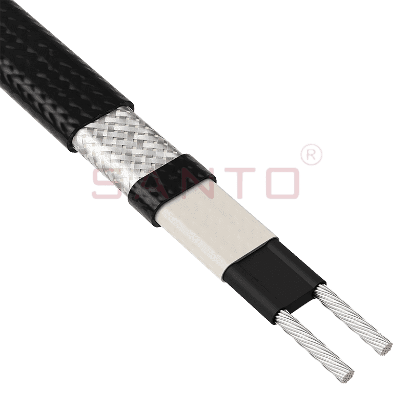
The SANTO UFA range of self-regulating heating cables is mainly used for frost protection of pipes and vessels but can also be used to maintain processes up to 65°C. These heating cables are available...
See Details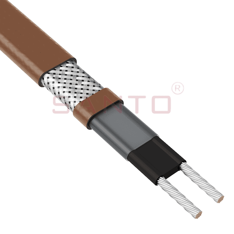
The SANTO UFB range of self-regulating heating cables is mainly used for frost protection of pipes and vessels requiring a higher power output than the UFA heating cables can supply. They can also be ...
See Details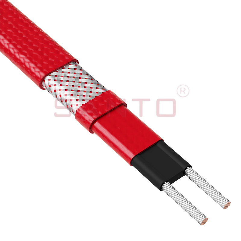
The SANTO UFC range of self-regulating heating cables is used for frost protection of pipes and vessels that require steam cleaning. They can also be used to maintain processes up to 121°C. These heat...
See Details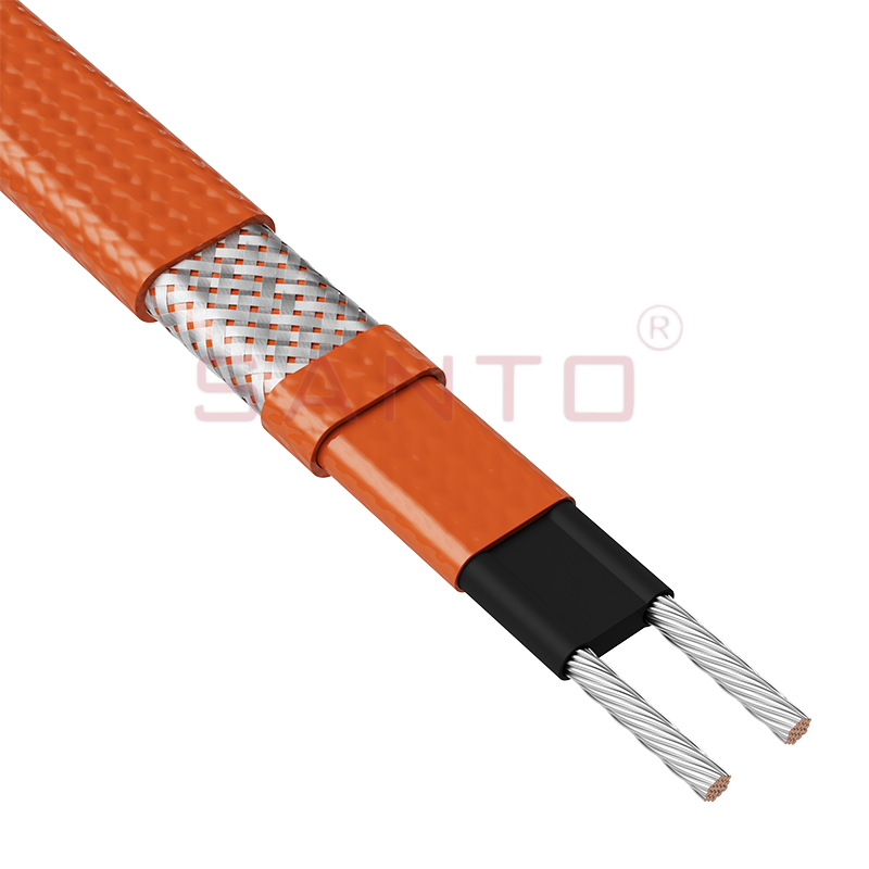
The SANTO UFO range of self-regulating heating cables is mainly used for frost protection of pipes and vessels that require steam cleaning . They can also be used to maintain processes up to 150°C. Th...
See Details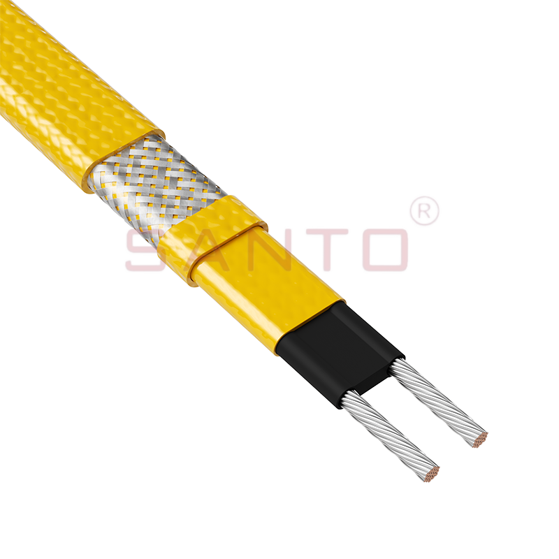
The SANTO UFD series of self-regulating heating cables are mainly used for freeze protection of pipes and vessels, but can also be used to maintain processes up to 200°C. These heating cables are avai...
See Details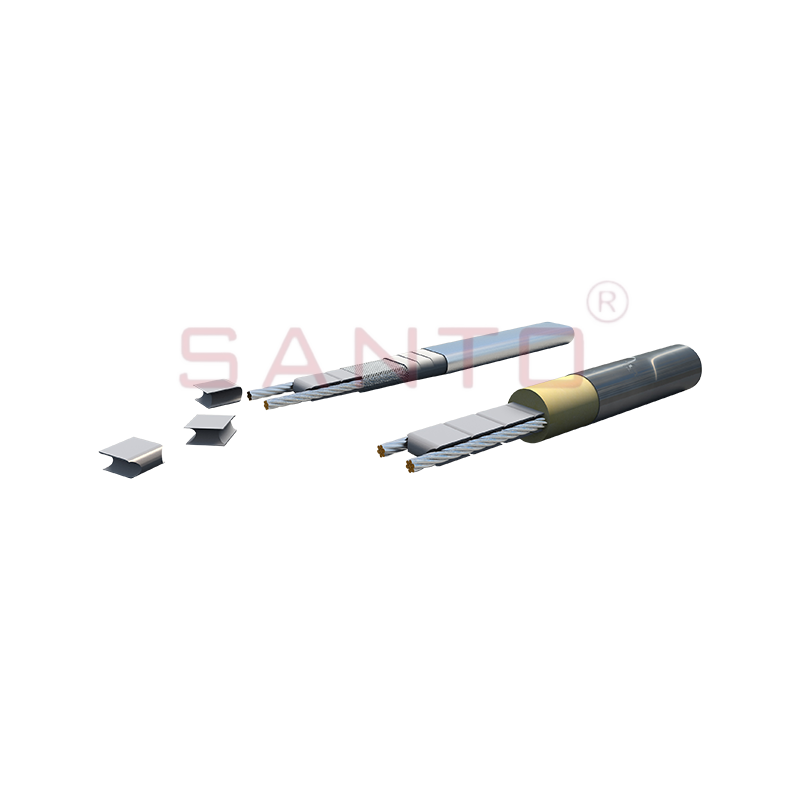
SANTO UFY heating wire is suitable for applications that maintain process temperatures up to 260 ℃ and can be steam blown; The self-regulating and parallel circuit heating wires of the UFY series are ...
See Details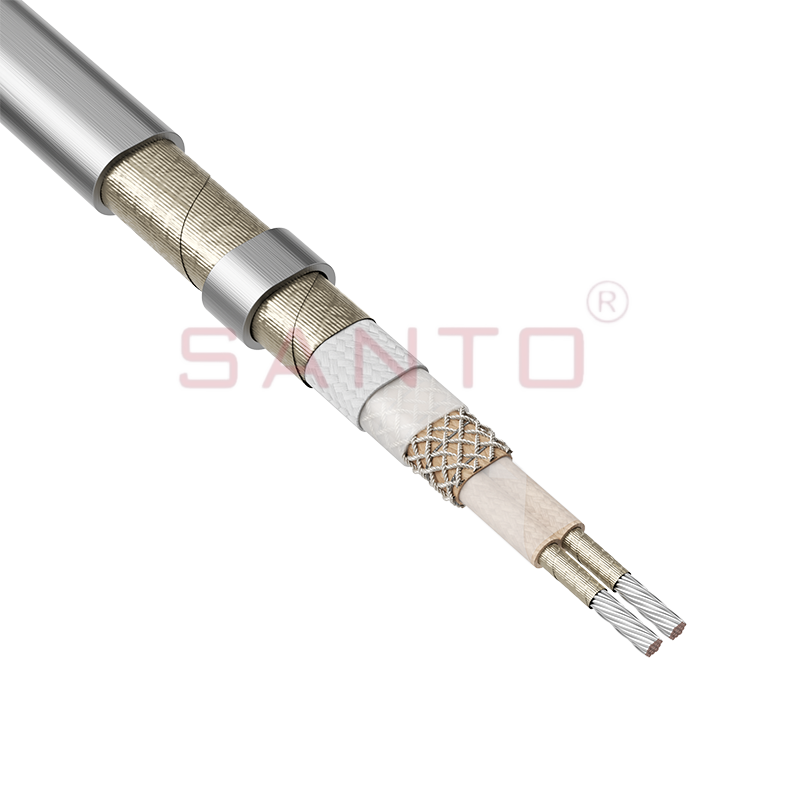
The SANTO UFM series self-regulating heating cables are mainly used for freeze protection of pipes and vessels, but can also be used to maintain processes up to 400°C. These heating cables are availab...
See Details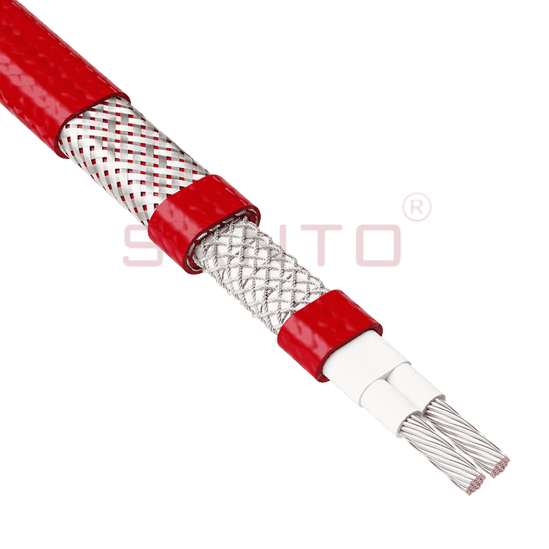
The SANTO ACC range of power-limiting heating cables is mainly used for temperature maintenance of processes and offers the advantage of a high power output at high temperatures which can reduce the n...
See Details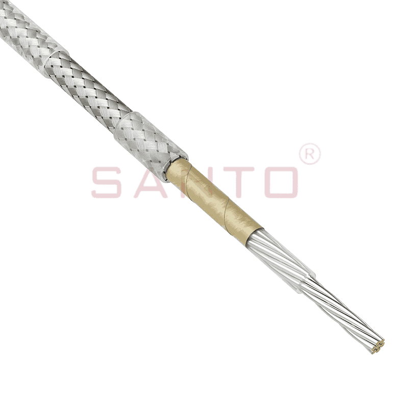
The stranded high temperature conductor is nickel plated to ensure a long life at elevated temperatures in corrosive environments. It is electrically isolated using an innovative sandwich construction...
See Details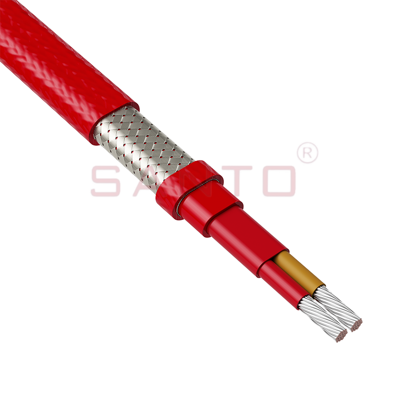
The stranded high temperature conductor is nickel plated to ensure a long life at elevated temperatures in corrosive environments. It is electrically isolated using an innovative sandwich construction...
See Details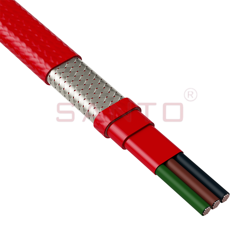
The stranded high temperature conductor is nickel plated to ensure a long life at elevated temperatures in corrosive environments. It is electrically isolated using an innovative sandwich construction...
See Details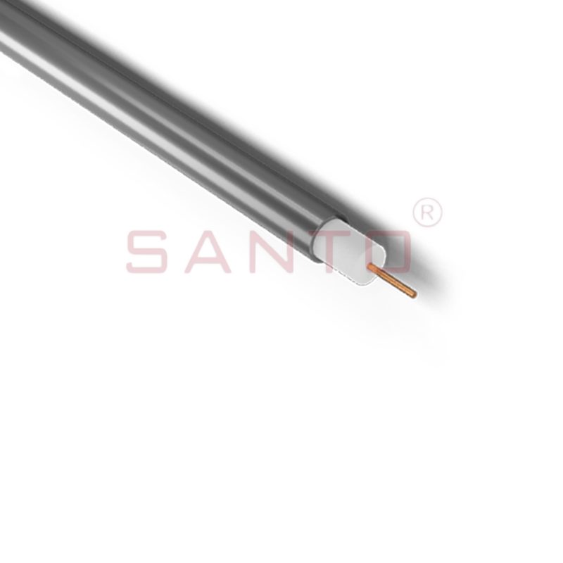
SANTO HAx mineral insulated (MI) Alloy 825 series heating cables are suitable for use in hazardous areas. They have been designed for use in freeze protection and temperature maintenance applications ...
See Details
Santo electric heating strips are widely used in key industries in China.

