 English
 English
 русский
 日本語
 Español
 中文简体

The SANTO UFA range of self-regulating heating cables is mainly used for frost protection of pipes and vessels but can also be used to maintain processes up to 65°C. These heating cables are available...
See Details
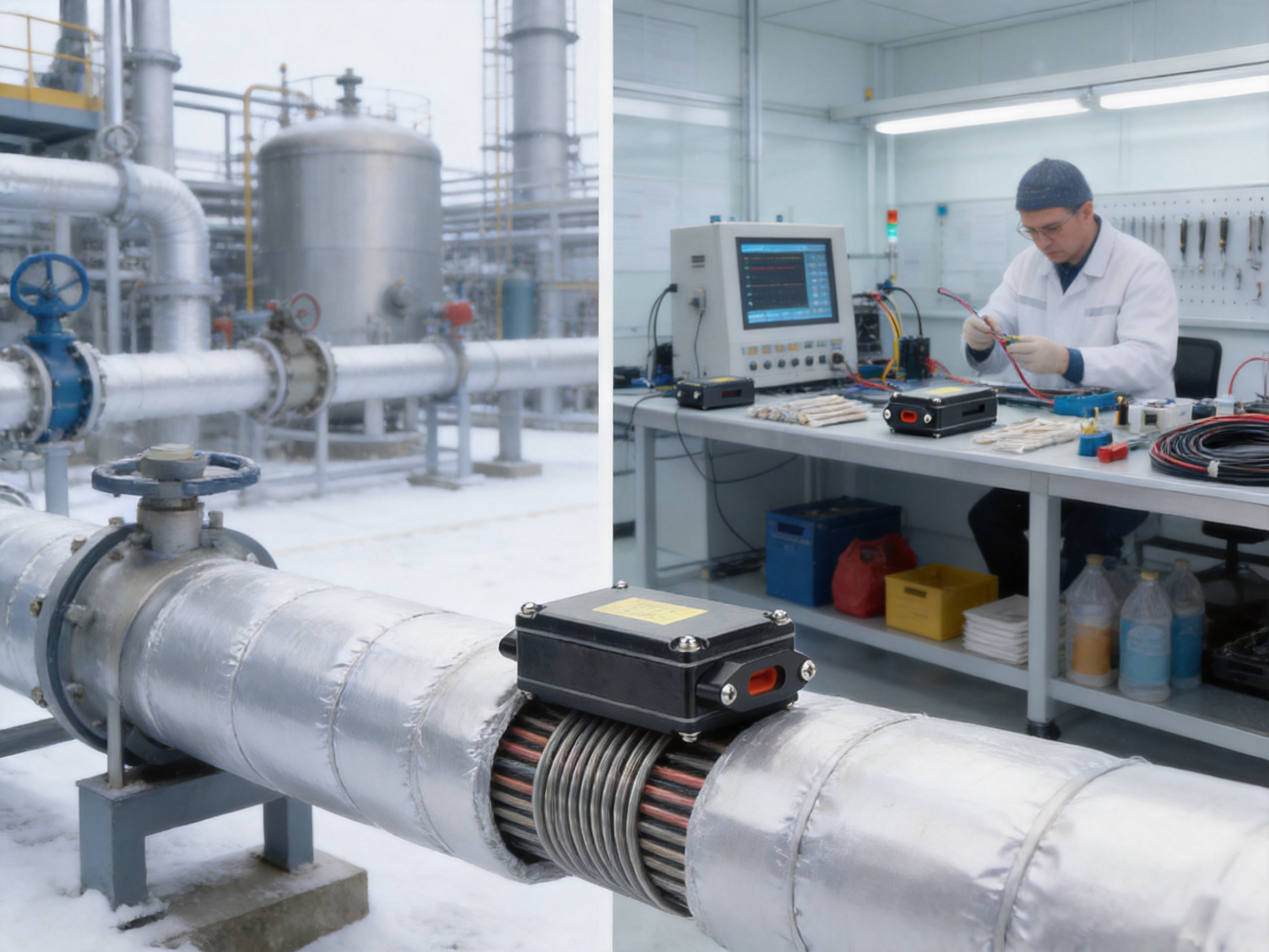
Reliable electrical connections are essential to the safe and efficient operation of heat-tracing systems. A self-regulating heating cable may adjust its heat output according to surrounding temperature, but its performance still depends on correctly installed junctions, properly protected conductors, secure mechanical connections, and suitable electrical insulation. The JQH-LSC two-way junction box is designed to address these requirements in pipeline heat-tracing applications.
As a dedicated power junction box for self-regulating heating wires, the JQH-LSC provides an organized enclosure for two-way cable connections. It is fixed directly on the pipeline during installation, while the thermal insulation layer is placed over the outside of the completed assembly. The design allows the materials used for the two-way connection to be positioned inside the box, helping keep the connection protected, orderly, and accessible during installation and inspection.
The product complies with applicable IEC requirements and can be used in Ex el hazardous areas when installed according to the relevant project specifications, certification requirements, and installation instructions. This makes it suitable for industrial heat tracing where electrical reliability, fire prevention, and controlled installation procedures are especially important.
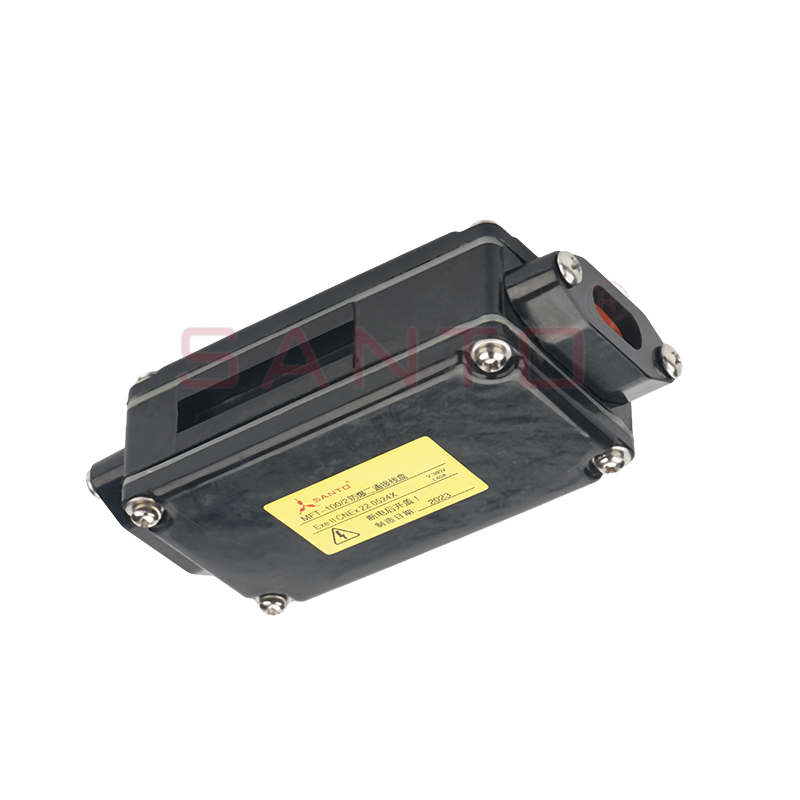
JQH-LSC two-way junction box
Content
Heat-tracing systems are installed to maintain the temperature of pipelines, valves, tanks, instruments, and process equipment. They can prevent freezing, compensate for heat loss, maintain viscosity, support process temperature control, and assist with snow and ice prevention. In every one of these applications, the heating cable must be connected to the power supply and, in many cases, routed through a junction or branch point.
The junction is one of the most sensitive points in the system. A heating cable is often installed in an environment exposed to moisture, temperature changes, vibration, mechanical movement, chemicals, or outdoor conditions. If the cable connection is poorly made, the consequences may include leakage current, overheating, short circuits, loss of heating performance, or damage to surrounding insulation.
A general-purpose electrical enclosure may not provide the practical arrangement required for self-regulating heating cable connections. Heating cable conductors, conductive polymer layers, braid or shielding components, insulation, and connection accessories must be handled carefully. The enclosure should provide sufficient space for the connection components while allowing the installer to work accurately without damaging the cable.
The JQH-LSC is designed specifically for this type of application. Rather than treating the junction as an improvised connection inside a generic box, the product provides a purpose-designed enclosure and a set of associated components for completing the two-way connection. This approach helps standardize field installation and reduces the possibility of inconsistent workmanship between projects.
The primary function of the JQH-LSC is to provide a two-way connection for self-regulating heating wires. The box is installed at the selected point on the pipeline, and the connection materials are placed within the enclosure. Once installation has been completed and inspected, the pipeline insulation can be applied around the assembly.
The two-way arrangement is useful when a heating circuit must be connected, extended, or arranged along a pipeline route. It supports a clean and controlled transition between heating cable sections or between the heating cable and the associated power connection, depending on the project design and approved installation method.
The enclosure helps keep the electrical connection components together and separated from the external environment. The box does not eliminate the need for correct sealing, insulation, cable preparation, grounding, leakage protection, or inspection. Instead, it provides the physical framework within which those tasks can be performed correctly.
Because the box is fixed to the pipeline and covered by the external insulation layer, it can become part of a neat and integrated heat-tracing installation. This arrangement helps avoid loosely suspended connection points and reduces the risk of accidental mechanical stress on the heating cable.
The JQH-LSC offers several practical advantages compared with non-specialized junction arrangements. These advantages relate to installation organization, compatibility with self-regulating heating cables, component completeness, suitability for industrial environments, and support for standardized safety procedures.
A purpose-built junction box is easier to use than an enclosure selected only for its general electrical function. The JQH-LSC is intended for self-regulating heating wire systems, so its component arrangement is oriented toward the preparation and protection of heating cable connections.
Self-regulating cables contain special conductive elements whose resistance changes with temperature. The installer must strip and prepare the cable without damaging the internal busbars or creating an unintended electrical bridge between conductors. A dedicated enclosure provides a more suitable working area for these operations than an improvised connection outside an enclosure.
The product is supplied with internal components that support the installation process. The standard contents include one cassette, three pressing plates with screws, three red washers, two pads, two cover plates with screws, and one nameplate. These parts are arranged to support the mechanical securing and protective finishing of the connection.
Having the required components packaged with the box can simplify material planning. It reduces the need for installers to source unrelated replacement parts and helps maintain consistency across multiple installation points. For large industrial projects, this can improve inventory control and make installation procedures easier to document.
The JQH-LSC is fixed on the pipeline during installation. This is important because a junction box should not be left unsupported, suspended from the cable, or placed where it can be struck by maintenance equipment. A stable mounting position helps protect the connection and makes the finished heat-tracing system more orderly.
After the junction box has been installed and tested, the external thermal insulation can be fitted over the pipeline. The installation team can therefore integrate the junction point into the same insulation system used for the rest of the heat-traced pipeline.
The JQH-LSC can be used in Ex el hazardous areas when the complete installation meets the applicable requirements. This is a significant advantage for industrial users working in petroleum, chemical, gas, energy, and other facilities where flammable atmospheres may occur.
Hazardous-area suitability must always be evaluated as part of the complete system. The box, cable, glands, power supply, protective devices, grounding arrangement, temperature classification, and installation method must be compatible with the area classification. The JQH-LSC should be selected and installed only in accordance with its technical documentation, project requirements, and approved safety procedures.
In heat-tracing work, many failures originate not from the basic heating principle but from installation errors. Examples include damaged busbars, insufficient insulation, moisture entering the connection, incorrect pressing, loose screws, contact between conductors, or the use of unapproved substitute materials.
The JQH-LSC helps create a repeatable process. The installer uses a defined box, defined internal parts, defined tools, and defined precautions. Standardization is especially valuable when a project includes hundreds or thousands of heating cable connection points.
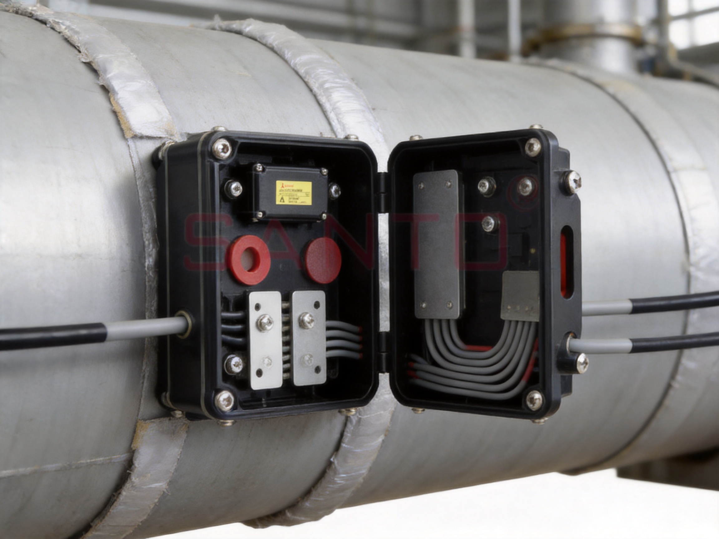
The internal configuration of the JQH-LSC is intended to support secure assembly and finishing of the two-way connection. Each component has a specific role in the installation process, and the installer should confirm the contents before beginning work.
| Item | Quantity | Component | General function |
|---|---|---|---|
| A | 1 | Cassette | Provides the main enclosure or internal support for the connection assembly. |
| B | 3 | Pressing plate with screws | Supports mechanical securing of the prepared connection components. |
| C | 3 | Red washer | Supports insulation, separation, or protective assembly as specified in the installation procedure. |
| D | 2 | Pad | Provides additional support or spacing within the connection arrangement. |
| E | 2 | Cover plate with screws | Helps close and protect the assembled connection. |
| F | 1 | Nameplate | Provides space for identification and installation information. |
The exact installation sequence should be taken from the approved product manual and project method statement. The table describes the supplied components at a general level; it should not replace the manufacturer’s detailed instructions.
The cassette forms the central structural part of the assembly. It provides a defined location in which the two-way connection materials can be placed. A dedicated cassette helps prevent the connection from moving freely within a larger empty enclosure.
Controlled positioning is valuable during installation and later inspection. When the connection components remain in their intended location, the risk of accidental contact, compression, or damage during closure is reduced.
The pressing plates and screws provide mechanical retention. They help hold the prepared connection in position and contribute to a stable assembly. Correct tightening is important. Screws should be tightened according to the installation instructions, and installers should avoid both under-tightening and excessive force.
Under-tightening may allow movement or reduce mechanical stability. Excessive tightening may damage insulation, deform components, or place unnecessary stress on the heating cable. A controlled installation method is therefore essential.
The red washers and pads are part of the supplied connection arrangement. They contribute to separation, support, insulation, or positioning as defined by the manufacturer’s installation procedure. They should not be replaced with unrelated materials because the electrical and mechanical behavior of a connection depends on the compatibility of all its parts.
The cover plates help complete the enclosure and protect the installed components. Before the covers are secured, the installer should verify that the cable preparation, insulation, conductor separation, mechanical retention, and internal cleanliness are satisfactory.
Closing the box without inspection can conceal a defect and make troubleshooting more difficult. A proper inspection before closure is therefore a critical quality-control step.
The nameplate provides an opportunity to identify the circuit, installation point, or other project information. Clear identification can simplify commissioning, periodic inspection, repair, and future expansion of the heating system.
The specified tools for the JQH-LSC installation include wire pliers, pointed pliers, a special tool knife, and a screwdriver. Each tool should be clean, suitable for electrical work, and maintained in good condition.
| Tool or material | Purpose in the installation process | Important consideration |
|---|---|---|
| Wire pliers | Cutting or handling conductors and cable components. | Use carefully to avoid crushing or nicking internal conductors. |
| Pointed pliers | Positioning small components and handling prepared cable sections. | Do not use excessive force on insulation or conductive layers. |
| Special tool knife | Removing specified insulation or conductive plastic layers. | Follow the required stripping depth and cutting direction. |
| Screwdriver | Installing pressing plates, cover plates, and screws. | Use the correct size and tighten according to the instructions. |
| GT-66 tape | Additional installation attachment for temperatures above 4°C. | Confirm the ambient and surface temperature before use. |
| GS-54 tape | Additional installation attachment for temperatures above -40°C. | Use the specified tape for the applicable low-temperature condition. |
The additional attachment information supplied for the product identifies GT-66 tape for installation temperatures above 4°C and GS-54 tape for installation temperatures above -40°C. The installer should verify the correct tape selection, storage condition, surface cleanliness, and application method before beginning work.
Tools used on self-regulating heating cables must be handled with particular care. A knife that is too sharp, incorrectly positioned, or used with excessive pressure may scratch the busbars. Pliers may compress insulation or deform the conductive material. A screwdriver with the wrong tip may damage the screw head or slip into the cable assembly.
Installation teams should use a documented work procedure and, where appropriate, provide practical training before field work begins. A consistent tool method is one of the simplest ways to reduce connection defects.
The black conductive plastic used in a self-regulating heating wire is an active part of the heating element. It must be treated differently from ordinary cable filler or external insulation. The conductive plastic should remain dry, should be insulated correctly, and should not create an unintended path between the busbars.
The busbars are the electrical conductors running through the heating cable. They must remain intact and must not touch each other. A damaged busbar may increase electrical resistance locally, create a hot spot, or produce an unstable connection. Contact between busbars can cause a short circuit.
When removing the external insulation or conductive plastic, the installer should follow the approved stripping sequence. The knife should be controlled so that it removes only the intended layer. Scratching, cutting, or scoring the busbars must be avoided.
If a busbar is damaged during preparation, the section should not simply be hidden inside the junction box. The installer should stop and follow the project procedure for rejection, repair, or replacement. Concealing damaged cable inside an enclosure can create a long-term reliability and safety problem.
Moisture control is essential. The conductive plastic and prepared connection must be protected from rain, condensation, dirty gloves, wet tools, and contaminated work surfaces. If installation takes place outdoors, temporary weather protection may be required.
A connection that appears acceptable when dry may become unsafe after moisture enters the assembly. Water can reduce insulation resistance, accelerate corrosion, and increase leakage current. The junction box should therefore be assembled only when the components and work area are clean and dry.
The two busbars must remain separated throughout preparation and final assembly. The installer should check the arrangement before applying pressing plates or closing the cover. Red washers, pads, insulation layers, and other supplied parts must be positioned as directed.
Electrical separation should be confirmed visually and, where required by the project procedure, by testing with suitable test equipment. Testing should be performed by qualified personnel using methods appropriate for the heating cable and hazardous-area environment.
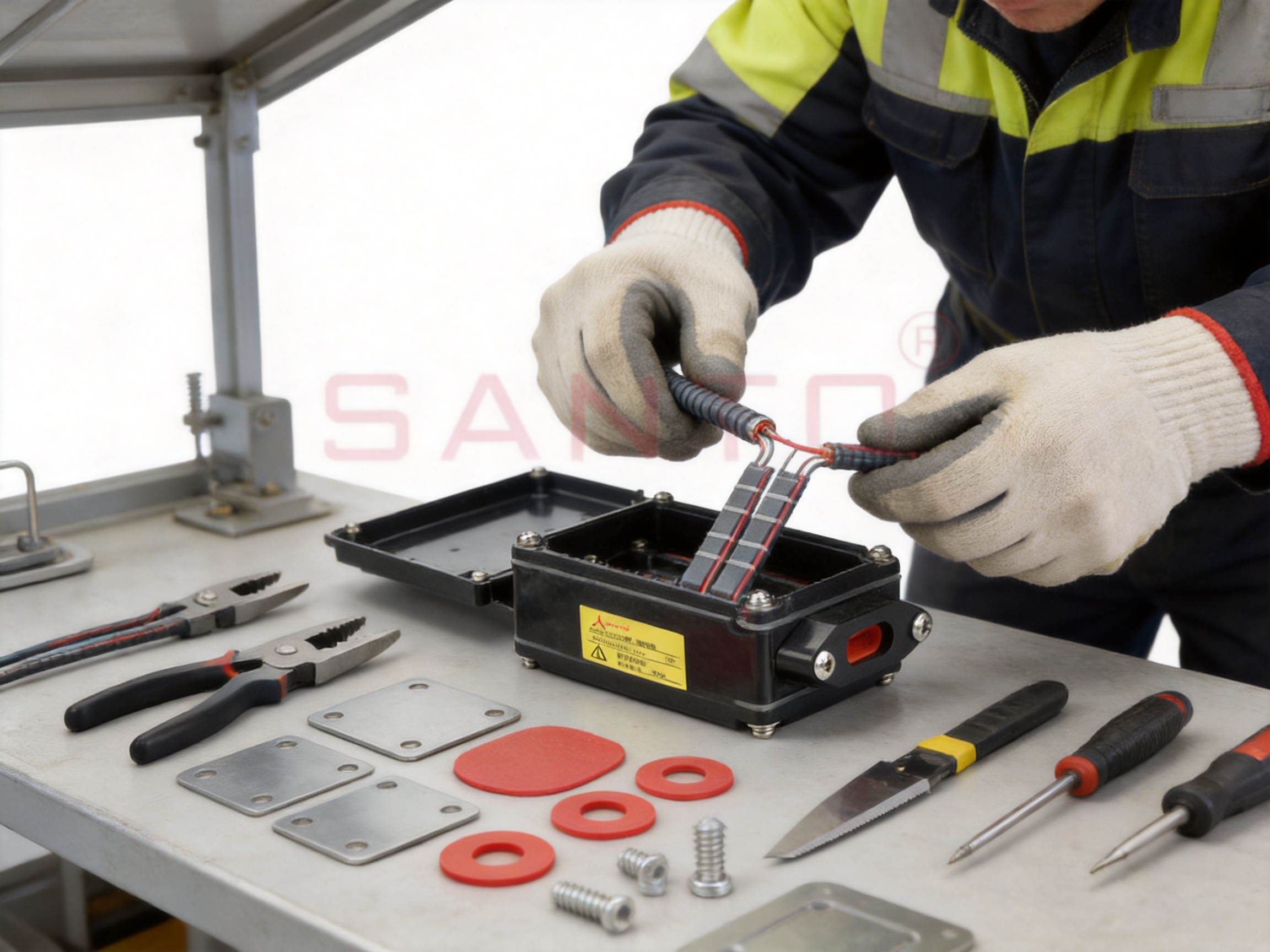
The JQH-LSC is an electrical product and must be installed and operated correctly. Fire resistance and fire prevention are important considerations because heat-tracing cables are often installed in insulation systems that can conceal a developing fault.
Before work begins, the installer should read the product precautions and installation manual. The manual should be treated as a required part of the product, not as optional background information. It defines the correct preparation sequence, component arrangement, restrictions, and inspection requirements.
Project drawings and hazardous-area documentation must also be reviewed. The position of each junction box should be confirmed in relation to pipeline supports, valves, flanges, insulation joints, access platforms, and maintenance areas.
Leakage protection devices should be installed to help prevent fires caused by damaged heating cables or improper installation. The protective device must be selected and coordinated by a qualified electrical designer. Its settings should be compatible with the circuit load, cable characteristics, operating environment, and applicable regulations.
Leakage protection does not replace correct installation. It is an additional protective measure. Damaged insulation, wet connections, conductor contact, and incorrect cable preparation must still be prevented through good workmanship and inspection.
Only standard approved components should be used with the JQH-LSC. Substitutes should not be introduced without formal technical approval. In particular, ordinary PVC insulation tape must not be used as a replacement for specified components or approved installation materials.
Different materials may have different temperature ratings, adhesion characteristics, chemical resistance, electrical insulation properties, and fire behavior. A substitute that appears satisfactory during installation may fail during long-term heating or exposure to industrial conditions.
For Ex el hazardous-area use, all work must comply with the area classification and the relevant explosion-protection requirements. Installation personnel should be qualified for hazardous-area electrical work. Equipment isolation, permit-to-work procedures, grounding, cable entry arrangements, and inspection documentation must be controlled.
The suitability of the complete assembly depends on more than the junction box alone. The heating cable and all accessories must be appropriate for the area, temperature, and process conditions. Any uncertainty should be resolved with the responsible electrical engineer or product technical department before installation.
The following workflow provides a general understanding of how the JQH-LSC may be installed. It is not a replacement for the official installation manual, which should always govern field work.
First, confirm the pipeline identification, heating circuit number, junction location, cable route, and applicable area classification. The installation point should be accessible for assembly and inspection while remaining compatible with the final insulation arrangement.
Verify that the cassette, pressing plates, red washers, pads, cover plates, screws, and nameplate are present. Check the box and components for visible damage, contamination, deformation, or missing parts. Do not install damaged components without technical evaluation.
The pipeline surface should be clean and suitable for mounting. Oil, loose rust, dust, moisture, and other contaminants can reduce the quality of the attachment. The selected tape should correspond to the installation temperature and the approved procedure.
Place the heating cable according to the project drawing and ensure that it is not under unnecessary tension. The cable should be routed without sharp bends, crushing, twisting, or abrasion. The junction box should be aligned so that the cable enters the assembly naturally.
Using the specified tool knife and pliers, remove the required layers carefully. The stripping sequence should expose the correct parts without damaging the busbars. The black conductive plastic must remain dry and must be insulated as directed.
Place the prepared cable and connection materials inside the cassette. Install the red washers, pads, pressing plates, and screws in the specified order. The components should be positioned neatly, with no conductor crossing or unwanted contact.
Inspect the connection for damaged insulation, exposed conductive plastic, loose components, contact between busbars, misplaced washers, contaminated surfaces, and incorrect screw installation. Electrical tests should be performed according to the project inspection plan.
After the assembly has passed inspection, install the cover plates and secure them with the supplied screws. Complete the nameplate information so that the circuit and location can be identified later.
Once the connection has been completed and accepted, the pipeline insulation can be applied around the junction area. The insulation must be installed without crushing the box, pulling on the cable, blocking required access, or creating a condition that conflicts with the product’s technical requirements.
The JQH-LSC is suitable for applications involving self-regulating heating cables. These systems are widely used where temperature maintenance and freeze protection are required.
Process lines in petroleum and chemical plants may require heat tracing to prevent crystallization, maintain fluidity, protect instruments, or avoid freezing. Junction points in these areas must be organized and compatible with the plant’s safety requirements.
Gas facilities, power plants, and energy installations may use heating cables around pipes, valves, drains, and equipment exposed to low temperatures. A reliable junction enclosure helps support the continuity of the heating system and simplifies maintenance planning.
Outdoor pipelines face rain, snow, wind, ultraviolet exposure, and temperature changes. Although the entire installation must be designed for the environment, a dedicated junction box helps provide a defined location for protecting the connection beneath the thermal insulation system.
Self-regulating heat tracing is also used for water lines, roof drainage systems, fire-protection pipes, loading areas, and other building services. In these applications, a neat and clearly identified junction can make future inspection easier for facility operators.
Heating cables used for snow and ice melting may be installed near ramps, walkways, roofs, gutters, and exposed infrastructure. The JQH-LSC is primarily described for pipeline installation and self-regulating heating wires, so users should confirm suitability for any non-pipeline application with the technical documentation and project designer.
The performance of an electrical accessory depends not only on its visible enclosure but also on the manufacturer’s quality systems, engineering experience, process control, and ability to support the complete heating technology chain.
Santo Thermal Control Technology Co., Ltd. is an established manufacturer of electric heating and heat-tracing products. Its product scope includes self-limiting electric heating belts, constant-power heating belts, silicone rubber heating belts, glass fiber heating belts, MI cables, snow-melting cables, electric heating wires, and related accessories.
The company reports more than 35 years of industry experience. Its development history began with the establishment of Desheng Electric Heating Instrument Factory in 2000, followed by quality-system development, product expansion, research activities, and international market development.
Long-term experience is valuable in heat-tracing manufacturing because the product must perform under electrical, thermal, mechanical, and environmental stresses. Experience gained from different cable types and applications can support better accessory design and more practical installation guidance.
The company cooperates in product research with Harvard University in the United States and has developed technologies involving self-limiting temperature nano far-infrared heating and carbon fiber parallel heating cable systems. It also reports multiple invention patents connected with its heating technologies.
Although the JQH-LSC is a junction box rather than a heating element, accessory design benefits from understanding the structure and behavior of the heating cables with which the accessory is used. Knowledge of conductive polymers, busbars, insulation, heat output, and installation conditions supports more coordinated product development.
The company established an irradiation center in 2013. Irradiation processes may be used in the production or treatment of certain cable materials, depending on product design and applicable procedures. The company also reports the construction of a product simulation testing laboratory as part of its continuing development.
Testing and simulation are important for evaluating heating products under representative electrical and thermal conditions. They can support process verification, product improvement, and the investigation of performance under different operating environments.
The company passed ISO 9001:2000 quality-system certification in 2002 and continues to emphasize scientific management, product quality, technical guidance, and after-sales service. A quality-management system can help control purchasing, production, inspection, documentation, nonconforming products, and customer feedback.
The company also reports national CCC certification for its products and explosion-proof and EAC Eurasian Union certifications obtained during its development. Certification status varies by product and model, so customers should request the relevant certificate for the specific JQH-LSC configuration and intended application.
Competitor products may differ in enclosure construction, component supply, installation method, certification scope, and technical support. Direct comparison should always be based on verified specifications and project requirements. Nevertheless, the JQH-LSC presents several design priorities that can provide practical advantages over an improvised or non-specialized junction arrangement.
The most important advantage is application matching. The JQH-LSC is intended for self-regulating heating wires rather than being a general enclosure selected without reference to cable construction. This focus helps align the enclosure, internal parts, and installation procedure with the characteristics of the heating cable.
The inclusion of the cassette, pressing plates, washers, pads, cover plates, screws, and nameplate provides a more complete starting point than an empty enclosure. A complete package can reduce uncertainty about compatible parts and help project teams maintain a consistent bill of materials.
Repeatability is a major advantage in industrial projects. If every installer follows the same component arrangement and safety precautions, the finished junctions are more likely to have consistent mechanical and electrical characteristics.
The stated suitability for Ex el hazardous areas allows the product to be considered for applications where ordinary junction solutions may not be acceptable. The complete system still requires engineering review, but the product’s intended industrial positioning can simplify the initial selection process.
A manufacturer that produces heating cables and related accessories can provide more coordinated technical support than a supplier focused only on empty enclosures. The customer can discuss cable selection, heat output, circuit arrangement, accessories, installation, and after-sales requirements within a connected product portfolio.
For a professional heat-tracing installation, product quality and installation quality should be documented together. Recommended project records may include product model, circuit number, installation location, installer name, date, ambient temperature, selected attachment tape, inspection results, insulation resistance readings, leakage-protection verification, and photographs where required.
Documentation is particularly important in hazardous-area facilities and large process plants. It provides evidence that the product was selected correctly, installed according to instructions, and tested before the pipeline insulation was closed.
Manufacturers and contractors should also maintain traceability for batches where project requirements demand it. Traceability can help investigate field issues, coordinate replacement components, and identify opportunities for process improvement.
After commissioning, the junction box should be included in the heat-tracing maintenance program. Inspection frequency depends on the application, environmental exposure, criticality of the process, and applicable regulations.
Maintenance personnel should look for visible damage to the enclosure, movement caused by vibration, signs of moisture, damaged insulation, loose covers, corrosion, unusual heating, and changes in circuit resistance or leakage current. Any inspection in a hazardous area must follow the facility’s permit and equipment-isolation procedures.
If the pipeline insulation is removed, the junction box and cable should be inspected before the insulation is restored. Reassembly should use approved components only. Damaged washers, covers, screws, or cable sections should not be replaced with unapproved alternatives.
Electrical testing should be performed by qualified personnel. Test methods and voltage levels must be appropriate for the self-regulating heating cable and the connected control equipment. Test results should be compared with commissioning records whenever possible.
When requesting the JQH-LSC, customers should provide enough information for the manufacturer or distributor to confirm suitability. Useful information includes the heating cable model, circuit voltage, application, pipeline material, installation temperature, ambient temperature range, hazardous-area classification, insulation type, number of junction points, and required certification.
The customer should also confirm whether the project requires specific cable glands, mounting accessories, labels, inspection records, or packaging arrangements. If the installation is part of an export project, the buyer may need documentation in a specific language or format.
Santo Thermal Control Technology can support OEM and ODM heating cable requirements according to the supplied company information. This capability may be useful for customers seeking coordinated product packages, customized specifications, private labeling, or large-volume supply. Any customization should be confirmed through technical drawings, approved samples, written specifications, and quality agreements.
It is used to create and protect a two-way connection for self-regulating heating wires. The box is fixed to the pipeline, and the connection materials are placed inside the enclosure before the external insulation layer is installed.
The product can be used in Ex el hazardous areas when the complete installation meets the applicable certification, area-classification, temperature, grounding, and installation requirements. The relevant product documentation must be checked for the specific project.
The listed components are one cassette, three pressing plates with screws, three red washers, two pads, two cover plates with screws, and one nameplate.
The specified tools are wire pliers, pointed pliers, a special tool knife, and a screwdriver. The tools must be appropriate for electrical work and used carefully to avoid damaging the heating cable.
The supplied information identifies GT-66 tape for installation temperatures above 4°C and GS-54 tape for installation temperatures above -40°C. The installer should verify the correct selection and follow the official installation procedure.
No. The product instructions state that only standard approved components should be used and that substitutes or PVC insulation tape should not replace the specified materials.
The black conductive plastic is part of the heating cable’s conductive structure. Moisture can reduce insulation performance and increase the risk of leakage or malfunction. It should be protected from water and contamination during installation.
A scratched or damaged busbar may cause overheating, electrical instability, or a short circuit. The damaged section should be handled according to the approved repair or replacement procedure rather than concealed inside the box.
It is intended for self-regulating heating wires. Compatibility should be confirmed for the specific cable model, voltage, environment, connection method, and certification requirements before ordering.
Leakage protection helps reduce fire risk if the heating cable or connection becomes damaged or is installed improperly. It is an additional protective measure and does not replace correct cable preparation and inspection.
The product is designed to be fixed on the pipeline with an insulation layer placed outside. The insulation should be installed only after the connection has been completed, inspected, and accepted, and it must not damage or improperly compress the assembly.
Customers should provide the heating cable model, voltage, application, pipeline details, temperature conditions, hazardous-area requirements, quantity, certification needs, and any packaging or labeling requirements.
The JQH-LSC two-way junction box is a specialized accessory for self-regulating heating wire systems. Its design provides a defined enclosure for two-way connections, a complete set of internal components, pipeline-mounting compatibility, and potential use in Ex el hazardous areas when the complete system is correctly engineered and installed.
Its practical value lies in more than simply enclosing a cable connection. The product supports a repeatable installation method, helps organize the connection materials, and encourages disciplined handling of conductive plastic, busbars, insulation, and protective components. These features can provide an advantage over generic or improvised junction arrangements, particularly in industrial installations where long-term reliability and fire prevention are essential.
The product is supported by a manufacturer with extensive experience in electric heating technology, self-limiting heating cables, constant-power systems, silicone rubber heaters, MI cables, snow-melting cables, and related accessories. The company’s reported quality certifications, research activities, irradiation capabilities, product testing development, international experience, and OEM and ODM strengths provide a broader technical foundation for supplying heat-tracing solutions.
For best results, the JQH-LSC should be selected as part of a complete engineered heat-tracing system. Correct cable compatibility, approved components, qualified installation, leakage protection, hazardous-area compliance, electrical testing, and proper insulation work are all necessary to achieve safe and dependable operation.
1. Manufacturer-provided product information for the JQH-LSC two-way junction box.
2. Manufacturer-provided installation precautions and component list for self-regulating heating wire connections.
3. IEC principles applicable to electrical equipment, heat-tracing systems, and installation practices.
4. ISO 9001 quality-management system principles for manufacturing and product control.
5. Manufacturer-provided corporate history, product portfolio, certification information, and research and development profile.
6. General industrial guidance on electrical leakage protection, hazardous-area installation, pipeline heat tracing, and fire prevention.
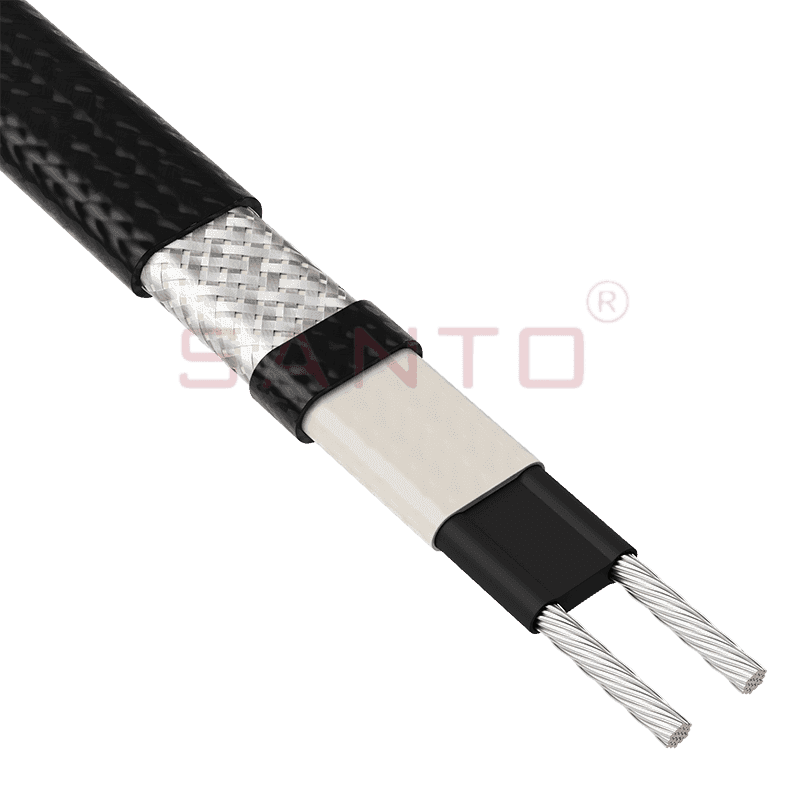
The SANTO UFA range of self-regulating heating cables is mainly used for frost protection of pipes and vessels but can also be used to maintain processes up to 65°C. These heating cables are available...
See Details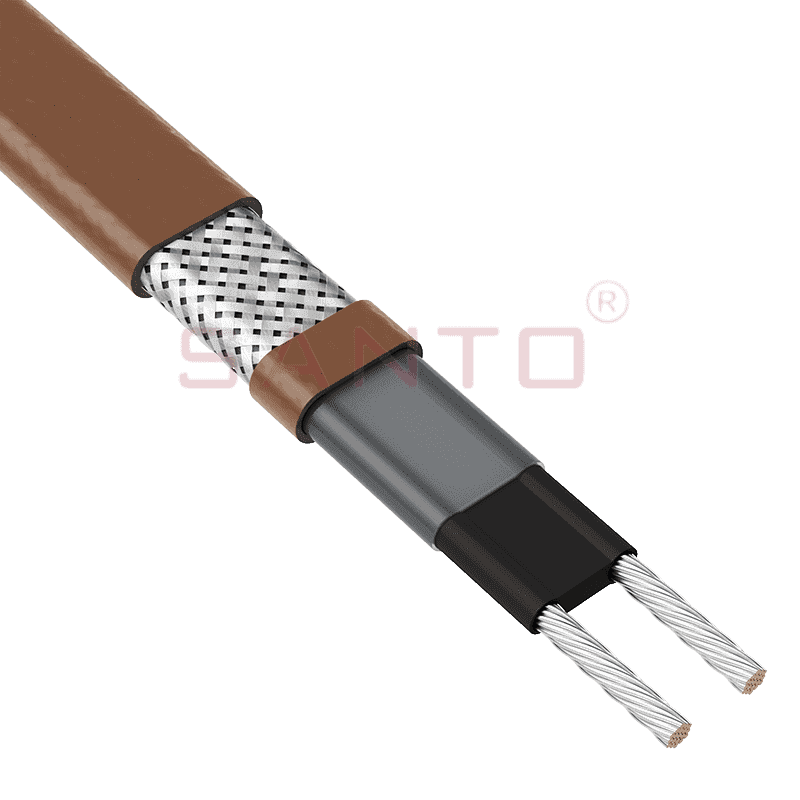
The SANTO UFB range of self-regulating heating cables is mainly used for frost protection of pipes and vessels requiring a higher power output than the UFA heating cables can supply. They can also be ...
See Details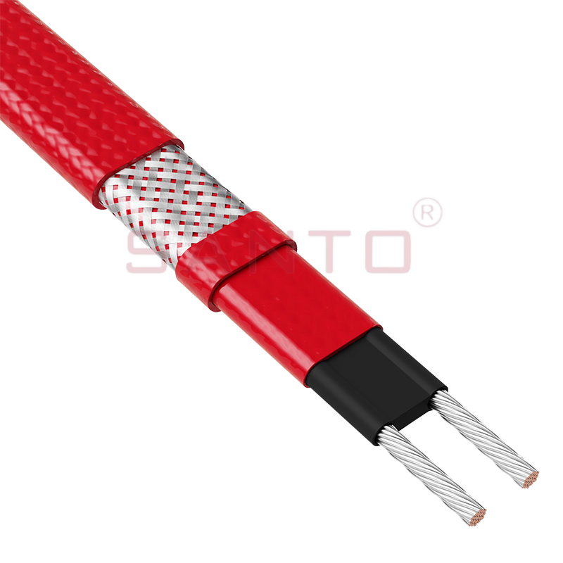
The SANTO UFC range of self-regulating heating cables is used for frost protection of pipes and vessels that require steam cleaning. They can also be used to maintain processes up to 121°C. These heat...
See Details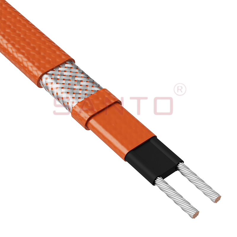
The SANTO UFO range of self-regulating heating cables is mainly used for frost protection of pipes and vessels that require steam cleaning . They can also be used to maintain processes up to 150°C. Th...
See Details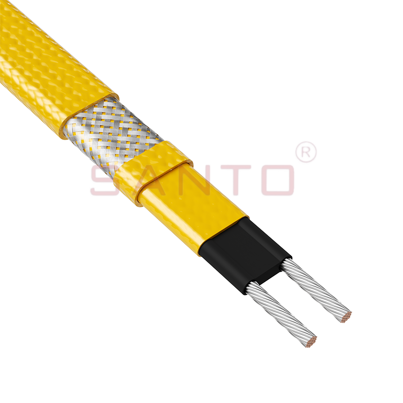
The SANTO UFD series of self-regulating heating cables are mainly used for freeze protection of pipes and vessels, but can also be used to maintain processes up to 200°C. These heating cables are avai...
See Details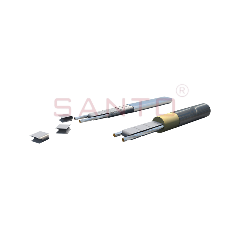
SANTO UFY heating wire is suitable for applications that maintain process temperatures up to 260 ℃ and can be steam blown; The self-regulating and parallel circuit heating wires of the UFY series are ...
See Details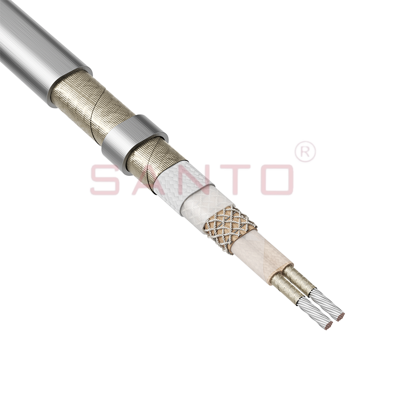
The SANTO UFM series self-regulating heating cables are mainly used for freeze protection of pipes and vessels, but can also be used to maintain processes up to 400°C. These heating cables are availab...
See Details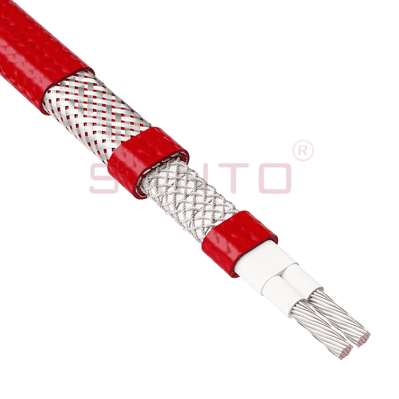
The SANTO ACC range of power-limiting heating cables is mainly used for temperature maintenance of processes and offers the advantage of a high power output at high temperatures which can reduce the n...
See Details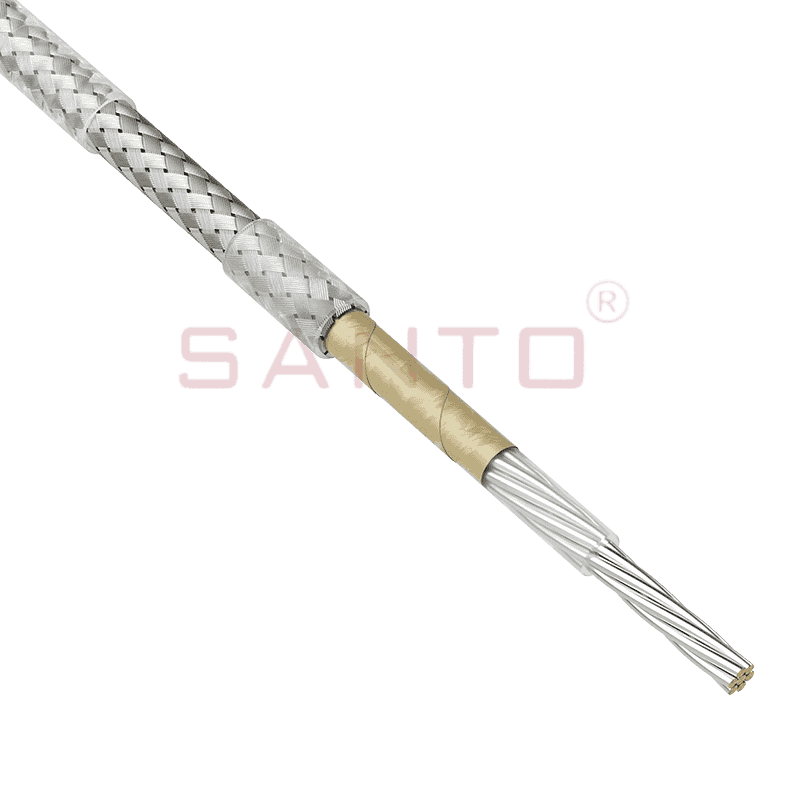
The stranded high temperature conductor is nickel plated to ensure a long life at elevated temperatures in corrosive environments. It is electrically isolated using an innovative sandwich construction...
See Details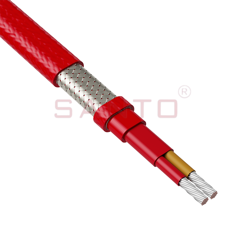
The stranded high temperature conductor is nickel plated to ensure a long life at elevated temperatures in corrosive environments. It is electrically isolated using an innovative sandwich construction...
See Details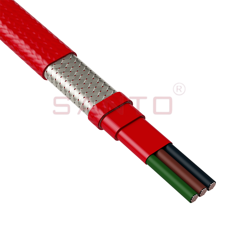
The stranded high temperature conductor is nickel plated to ensure a long life at elevated temperatures in corrosive environments. It is electrically isolated using an innovative sandwich construction...
See Details
SANTO HAx mineral insulated (MI) Alloy 825 series heating cables are suitable for use in hazardous areas. They have been designed for use in freeze protection and temperature maintenance applications ...
See Details
Santo electric heating strips are widely used in key industries in China.

