 English
 English
 русский
 日本語
 Español
 中文简体

The SANTO UFA range of self-regulating heating cables is mainly used for frost protection of pipes and vessels but can also be used to maintain processes up to 65°C. These heating cables are available...
See Details
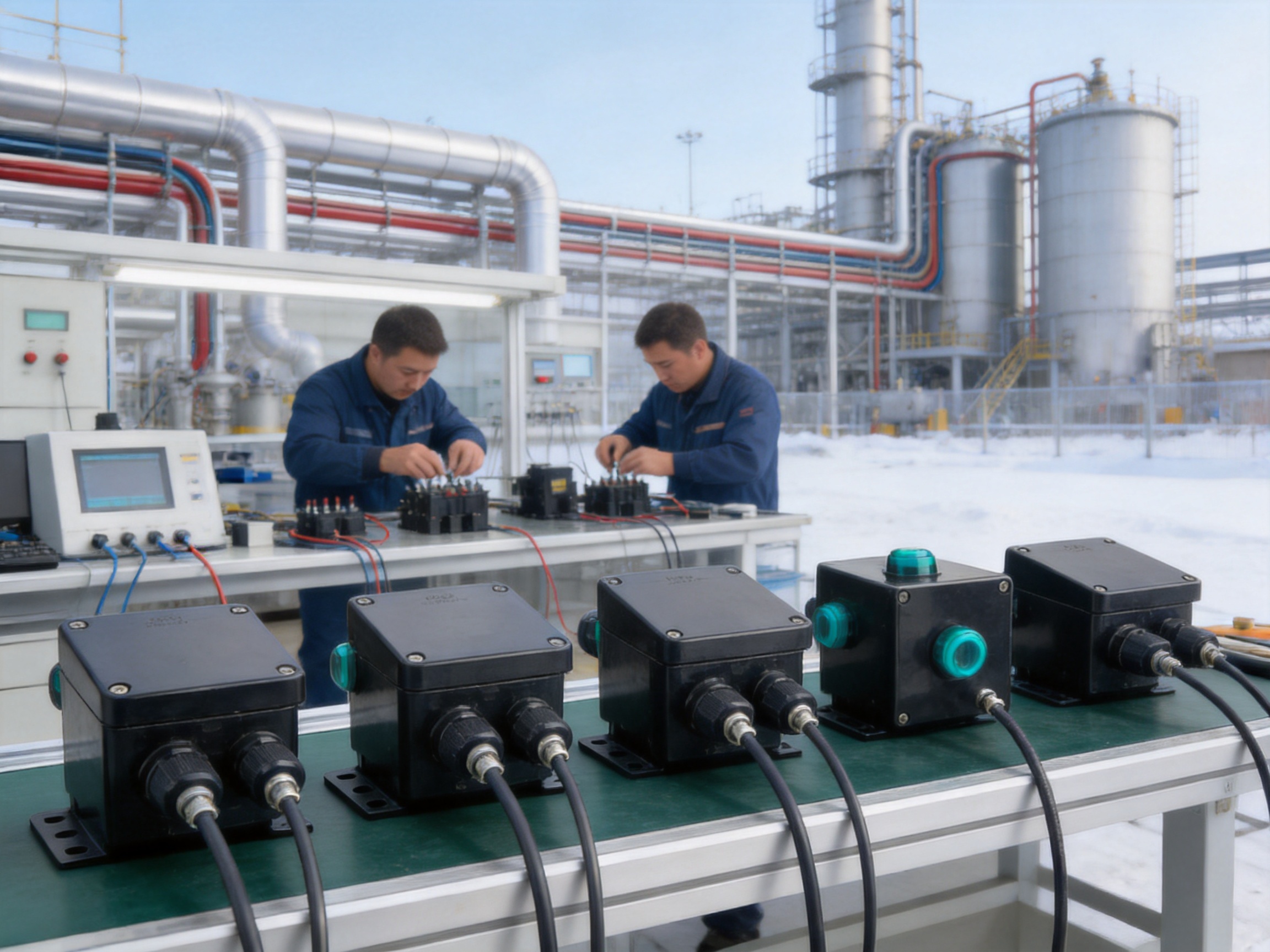
Reliable power connection is one of the most important elements in an industrial electric heating installation. Heating cable may be correctly selected, properly positioned, and professionally controlled, but the entire system can still experience downtime if its power supply junction box is not designed for demanding environmental conditions. Moisture, dust, corrosive atmospheres, mechanical stress, temperature changes, and installation limitations can all affect the safety and service life of the connection point.
The MFS-100-L-E and MFS-100-L-EP single-circuit power supply junction boxes are designed to address these challenges. They provide a practical and protected connection between the power supply and compatible parallel heating cables used for freeze protection, process temperature maintenance, pipeline heating, vessel heating, and other industrial heat-tracing applications. The kits are suitable for use with SANTO UFA, UFB, UFC, UFO, ABB ACC, ADD, AFF, and XP series heating cables, subject to the applicable product specifications.
Available in different configurations for Eurasian-region installations, the MFS-100 family combines a durable engineering-polymer enclosure, industrial terminal blocks, a heating-cable core sealing sleeve, mounting hardware, and optional visual power indication. The MFS-100-L-E version is intended for standard power cable entry through M25 components, while the MFS-100-L-EP version adds a grounding plate and external grounding bolt for installations using armored cables.
These kits are particularly valuable in hazardous areas because they are supported by recognized certifications and approvals, including CNEX, IECEx, ATEX, DNV, Baseefa, and EAC certification references stated for the product family. The combination of enclosure protection, certified components, electrical capacity, simplified installation, and manufacturing experience makes the system suitable for industrial users seeking a dependable connection solution rather than a basic general-purpose junction box.
Content
An electric heat-tracing system normally includes a heating cable, power supply, control equipment, temperature sensors, connection accessories, end seals, and mechanical supports. The power supply junction box is the transition point between the electrical distribution network and the heating cable. It must safely accommodate the incoming power conductors, connect the heating cable cores, maintain insulation integrity, and protect the terminals from the surrounding environment.
In an ordinary indoor electrical installation, these tasks may appear straightforward. Industrial heat tracing is more demanding. The junction box may be installed outdoors, on a pipe rack, near chemical equipment, or in a location where flammable gas or dust can be present. It may also be exposed to rain, condensation, snow, ultraviolet radiation, vibration, maintenance activity, and repeated thermal cycling.
The connection point must therefore perform several functions at the same time:
It must provide a secure electrical connection for the required current and voltage.
It must prevent water and dust from reaching energized parts.
It must support the heating cable mechanically and prevent excessive stress at the cable entry.
It must maintain the insulation system around the heating cable core.
It must provide an appropriate grounding arrangement for the selected cable and installation method.
It must allow installation at the actual site without unnecessarily complicated tools or hot-work procedures.
It must remain serviceable across the specified ambient-temperature range.
It must offer a clear indication of whether the junction box is energized when the indicator module is installed.
The MFS-100 design integrates these requirements into a compact kit. Instead of requiring an installer to source an enclosure, terminals, sealing components, bracket, cable gland, grounding accessories, and small installation materials separately, the kit brings the principal components together in one coordinated package.
The MFS-100 kit is designed to connect power to compatible parallel heating cables. The product information identifies applications with UFA, UFB, UFC, UFO, and ABB industrial parallel heating wire series. Because heating cable construction and electrical ratings vary, installers should always confirm compatibility with the applicable heating cable specification, design documentation, and local electrical requirements before installation.
The MFS-100-L-E configuration is intended for Eurasian-region applications and includes two M25 threaded holes. One M25 gland is supplied for power cables with a diameter of approximately 8 to 17 mm, while the other opening is closed with an M25 plug when not used. This arrangement provides flexibility for incoming power and installation requirements while maintaining the enclosure’s protection rating when the unused opening is correctly sealed.
The MFS-100-L-EP configuration is also intended for Eurasian-region applications. It includes two M25 threaded holes, an M25 plug, a grounding plate, and an external grounding bolt. This version is designed for installations involving armored cables, where the armor must be incorporated into a reliable grounding and bonding arrangement.
The “L” versions include an indicator module. The module uses an ultra-bright LED and is designed to be inserted into the wiring terminal. A viewing window in the cover allows personnel to see whether the junction box is energized without opening the enclosure. This feature can reduce unnecessary access to the terminals during inspection and can make routine field checks faster.
The kit is also available in a North American configuration identified as MFS-100-A or MFS-100-L-A in the supplied product information. That version uses a 3/4-inch through-hole and is rated for up to 277 Vac and a 50 A heating-wire circuit. The MFS-100-L-E and MFS-100-L-EP versions are rated for up to 254 Vac and 40 A heating-wire circuits. These differences demonstrate why the regional and cable-entry configuration should be selected before ordering.
| Configuration | Typical regional application | Power entry arrangement | Grounding arrangement | Maximum stated voltage | Maximum stated circuit current |
|---|---|---|---|---|---|
| MFS-100-A / MFS-100-L-A | North American installations | One 3/4-inch through-hole | Grounding wire and terminal arrangement | 277 Vac | 50 A heating-wire circuit |
| MFS-100-E / MFS-100-L-E | Eurasian-region installations | Two M25 openings; gland for 8–17 mm power cable and plug | Terminal-based grounding connection | 254 Vac | 40 A heating-wire circuit |
| MFS-100-EP / MFS-100-L-EP | Eurasian-region armored-cable installations | Two M25 openings with M25 plug | Grounding plate and external grounding bolt | 254 Vac | 40 A heating-wire circuit |
The table summarizes the principal differences. Exact certification markings, installation limitations, terminal arrangements, ambient ratings, and cable compatibility should be verified against the current product specification before purchase or installation.
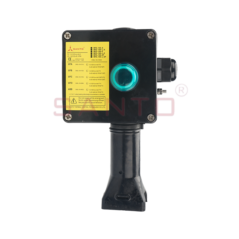
MFS-100-L-E/MFS-100-L-EP single circuit power supply junction box
The shell, lid, and bracket are made from black engineering polymer. This material selection provides a combination of electrical insulation, low weight, corrosion resistance, and practical mechanical durability. Unlike a conventional unprotected metal box, an engineering-polymer enclosure does not naturally create a conductive external surface that could become a path for corrosion or accidental contact. It is also easier to handle during installation, especially on pipe racks and elevated structures where minimizing component weight is helpful.
The enclosure is designed for industrial environmental protection. The E and EP versions are listed with IP66/IP67 protection grades, while the North American configuration is listed with NEMA 4X protection. These ratings are valuable in outdoor and process-industry applications because they indicate resistance to dust ingress and water exposure when the junction box is correctly assembled with suitable cable glands, plugs, seals, and covers.
Protection ratings are not achieved by the enclosure body alone. Correct installation is essential. The installer must tighten glands to the specified torque, use compatible cable diameters, ensure that plugs and sealing components are properly seated, avoid damage to the gasket, and close the cover evenly. The product’s protection performance depends on the complete assembly rather than one individual component.
Stainless-steel cover screws support repeated maintenance and help resist corrosion in damp or industrial atmospheres. Cover fasteners are often overlooked during product selection, yet they are important because they are exposed to the surrounding environment and may need to be removed during inspection. Corroded or damaged fasteners can make it difficult to reopen the enclosure and may compromise the cover seal during reassembly.
The cover gasket is made from silicone rubber. A flexible gasket helps form a continuous seal between the lid and enclosure body. Silicone rubber is also useful in applications with temperature variation because it can retain flexibility across a broad operating range. The gasket must remain clean, undamaged, and correctly positioned during installation. It should not be pinched between the cover and body, and it should not be contaminated with excessive lubricant or debris.
The EP configuration includes a galvanized, blue-chrome-plated steel ground plate and an external grounding bolt. This arrangement is intended for installations involving armored cable and provides a defined location for bonding the armor. A visible external grounding point can also assist inspection and continuity verification.
The E configuration uses a terminal-based grounding arrangement. The installation should follow the approved wiring diagram and applicable electrical code. In either case, grounding continuity should be checked before energization and after any maintenance work that affects the cable entry or terminal area.
The MFS-100-L-E and MFS-100-L-EP versions use WAGO 284 series terminal blocks identified for increased-safety applications. The terminal arrangement is specified for one phase, one neutral, and one grounding wire. These terminals are suitable for the stated conductor sizes, with the supplied information identifying a maximum of 10 mm² for multi-strand conductors and 10 mm solid electrical building wire.
The North American configuration uses a related terminal arrangement identified as two-wire plus one grounding wire and supports up to 8 AWG stranded wire. Its maximum stated working voltage is 277 Vac and its maximum stated heating-wire circuit is 50 A. The E and EP configurations are listed at 254 Vac and 40 A.
These ratings should not be interpreted as permission to exceed the heating cable manufacturer’s limits. The final circuit rating is determined by the complete system, including heating cable design, protective devices, ambient conditions, conductor size, installation method, control equipment, and local regulations. A junction box with a high rated capacity cannot increase the permitted current of an undersized heating cable.
The optional LED indicator consumes less than 1 W. It is rated for 100–277 Vac in the A version and 100–254 Vac in the E and EP versions. The A version uses a red indicator, while the E and EP versions use green indicators. The LED provides a convenient visual status signal, but it should not replace electrical testing, lockout procedures, or formal maintenance verification.
Industrial heating systems are frequently installed in petroleum, chemical, gas, storage, and process facilities. In these environments, a connection enclosure may be located where flammable gases, vapors, or combustible dusts can occur. Equipment used in such locations must be selected and installed according to the area classification and the relevant certification requirements.
The product information identifies CNEX, IECEx, ATEX, DNV, Baseefa, and EAC certification references for the product family. These approvals can support international project requirements and simplify equipment selection for facilities operating under different regulatory frameworks. However, certification should always be checked against the exact model, suffix, marking, gas or dust group, temperature class, ambient range, and installation conditions.
Certification is not a substitute for correct engineering. The installer must confirm that the junction box is suitable for the classified area, that the cable gland has the required approval, that the heating cable is compatible with the assembly, and that all unused openings are closed with approved plugs. The installation must also comply with the facility’s hazardous-area procedures, inspection requirements, and electrical safety rules.
The no-hot-work installation feature is another practical benefit in hazardous locations. When installing the core sealing sleeve, the supplied information states that there is no need to use a hot-air gun or spray lamp. This eliminates a high-temperature installation step and means that a high-temperature work permit is not required for that specific sealing operation, subject to the site’s own safety procedures. Reducing hot work can lower installation complexity and avoid introducing an ignition source near sensitive process equipment.
Industrial projects often involve difficult access, compressed schedules, and multiple contractors. A connection kit that contains the main components in a coordinated package can help reduce preparation time and the risk of missing small but important accessories. Depending on the selected configuration, the kit includes the junction box with terminal blocks, indicator module for L versions, mounting bracket, core sealing sleeve, yellow-and-green grounding sleeve, gland or plug, lubricant, and cable tie.
The mounting bracket is designed to support the enclosure and protect the heating cable connection. It is suitable for a 100 mm insulation layer according to the supplied information. This is important because many heat-tracing junction boxes are installed over insulated pipes or equipment. A bracket that accommodates the insulation thickness can help maintain a more organized installation and prevent the box from being forced against the insulation cladding.
The core sealing sleeve is designed to protect and seal the heating cable connection without requiring flame or hot-air equipment. The installer should follow the product installation instructions carefully, prepare the cable ends correctly, use the specified lubricant where required, and verify that the seal is complete before closing the enclosure.
The inclusion of a cable tie may appear minor, but small retention accessories can help maintain routing discipline inside and around the box. Organized conductors reduce the likelihood of accidental stress on terminal connections and make later inspection easier.
A factory-supplied kit also reduces the risk of mixing incompatible components. When an installer sources terminals, cable glands, sealing compounds, brackets, and enclosures from different suppliers, the resulting assembly may have uncertain compatibility. A coordinated kit provides a clearer basis for documentation, procurement, and quality inspection.
The indicator module is one of the most user-oriented features of the L versions. It contains an ultra-bright LED that is connected through the wiring terminal. A viewing window in the lid allows the operator to see whether the junction box is powered without opening the enclosure.
In large heat-tracing installations, dozens or hundreds of connection points may be distributed throughout a plant. A visible indicator can make a preliminary walkdown more efficient. Maintenance personnel can identify an apparently energized point before opening the cover, while operators can quickly recognize whether a circuit has power during routine rounds.
The indicator should be treated as a status aid rather than a safety device. A dark LED may indicate that the circuit is de-energized, that the protective device has opened, that the indicator has failed, or that the circuit is outside the indicator’s operating conditions. Conversely, a lit LED does not replace a verified isolation procedure. Before opening the enclosure, qualified personnel must follow the site’s lockout and electrical test requirements.
The E and EP versions are listed with IP66/IP67 protection. IP66 indicates protection against dust and powerful water jets, while IP67 indicates protection against temporary immersion under the conditions defined by the relevant standard. The North American version is listed with NEMA 4X protection, which is associated with protection against water, dust, and corrosion under the applicable enclosure standard.
These ratings make the product suitable for many outdoor and industrial applications, including pipeline heat tracing, tank heating, freeze protection, roof and gutter protection, and process equipment temperature maintenance. Nevertheless, the junction box should not be installed in a location that exceeds the specified environmental limits or exposes it to chemicals known to attack the enclosure, gasket, cable gland, or terminal materials.
The stated temperature range for the E and EP family is generally from -50°C to +40°C for the standard versions, with product-specific references distinguishing JBS and MFS-L versions in the supplied information. The minimum installation temperature is listed as -50°C. Users should consult the current technical specification for the exact model and indicator combination, particularly where low-temperature installation and operation are both required.
The maximum pipeline temperature is not a universal value for the junction box. It is to be determined by reference to the specifications of the companion heating cable. The enclosure and connection kit must be installed in a way that keeps the electrical components within their permitted operating conditions. Thermal insulation, heat transfer from the pipe, and the heating cable’s maximum exposure temperature all influence the final design.
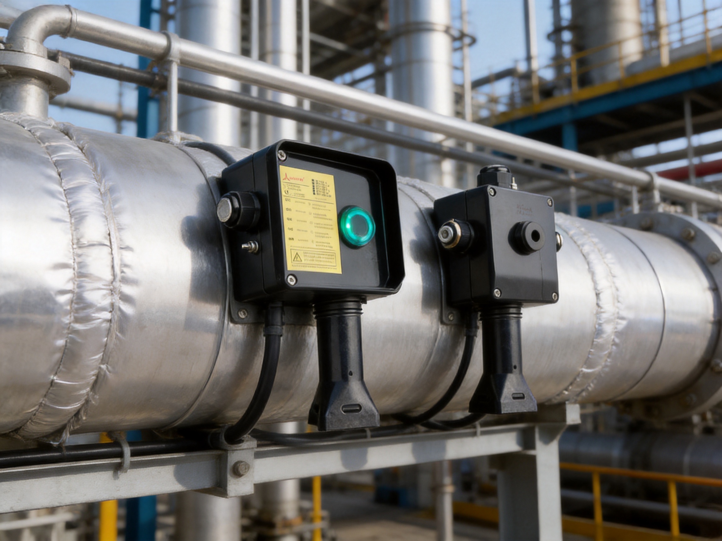
A basic junction box may provide only an enclosure and a few terminals. The MFS-100 kit is more comprehensive. It combines the housing, terminal block, mounting bracket, sealing sleeve, grounding accessories, cable-entry components, lubricant, and cable tie. This integrated approach helps reduce procurement effort and makes the intended installation sequence clearer.
General-purpose electrical boxes are not necessarily designed for the special geometry and insulation requirements of parallel heating cable. The MFS-100 kit is specifically intended for compatible industrial heating cables and includes a core sealing sleeve and bracket suited to heat-tracing installations. This application-specific design can provide a better fit than adapting unrelated electrical hardware.
Certification references for hazardous-area use distinguish the product from ordinary commercial junction boxes. Industrial users can evaluate the kit as part of a certified heat-tracing installation rather than attempting to assemble a hazardous-area connection from uncoordinated components.
The core sealing sleeve can be installed without a hot-air gun or spray lamp. This can be an important advantage in operating plants where hot work is restricted, costly, or slow to authorize. It can also reduce the number of tools that technicians must carry to elevated or remote installation points.
The availability of A, E, and EP configurations supports different cable-entry practices, voltage systems, and grounding requirements. The E version is suited to standard M25 power entry, while the EP version is intended for armored-cable applications. The ability to select a regional configuration is more practical than forcing one enclosure design to cover every market.
The optional LED and cover viewing window provide a convenient way to identify the apparent energized state of the junction box. This is particularly useful in large facilities where rapid visual checks are part of routine maintenance.
Engineering polymer, stainless-steel screws, silicone-rubber sealing, and the plated steel grounding plate in the EP version are selected for demanding service conditions. This combination offers advantages over unprotected materials that may corrode quickly in outdoor or process environments.
The manufacturer, Santo Thermal Control Technology Co., Ltd., specializes in electric heating and thermal-control products. Its product range includes automatic temperature-control heating belts, self-regulating heating belts, heat-tracing belts, constant-power heating belts, glass-fiber heating belts, mineral-insulated cables, silicone-rubber heating products, snow-melting cables, and related accessories.
This concentration on electric heating technology is significant for a connection accessory. A manufacturer that designs and produces heating cables, heating systems, and accessories can develop the junction box around the practical requirements of complete heat-tracing installations. Understanding cable construction, power distribution, insulation, temperature exposure, sealing, and field maintenance helps create a more coordinated product family.
The company reports more than 35 years of industry experience, an annual output exceeding 10,000 units or products across its business, more than 2,000 distributors, and business coverage in more than 85 areas. These figures indicate an established manufacturing and distribution platform capable of supporting both standard orders and project-based requirements.
The company’s history includes the establishment of an electric-heating instrument factory in 2000, ISO9001:2000 quality-system certification in 2002, an irradiation center in 2013, the creation of the SANTO brand in 2016, and expansion of manufacturing and product-testing facilities in later years. The company also states that it has developed proprietary heating technologies and obtained invention patents related to self-limiting and carbon-fiber heating products.
For industrial customers, the value of this background is not limited to production volume. It suggests experience in material selection, resistance-wire and cable processing, insulation systems, electrical testing, product documentation, and application support. These capabilities are relevant when manufacturing junction boxes and accessories that must work reliably with heating cables in real installations.
The company describes cooperation in product research with Harvard University in the United States and identifies itself as a high-tech enterprise in Jiangsu Province. It also reports research into automatic temperature-control heating systems, self-limiting technology, constant-power heating, silicone-rubber heating products, and other specialized electric-heating solutions.
Research and development experience can support continuous improvement in accessory design. For example, practical field feedback may lead to better sealing methods, improved terminal layouts, more convenient brackets, clearer status indication, and more suitable configurations for different regions. A junction box is a relatively compact product, but its performance is influenced by the heating cable, insulation, gland, enclosure, and installation method as a system.
The company states that it has passed ISO9001 quality-system certification and that its products have obtained national CCC certification. It also emphasizes scientific management, product quality, technical guidance, and after-sales service. These elements are important for industrial buyers who require repeatability between batches and supporting documentation for project approval.
Quality management should include incoming material inspection, dimensional control, terminal assembly, enclosure sealing verification, electrical continuity checks, indicator testing, label and model verification, and final packaging inspection. For hazardous-area products, traceability and certification control are particularly important because the final assembly must correspond to the approved product configuration.
The company reports the creation of an irradiation center and the construction of a product simulation testing laboratory. Such facilities can support evaluation of heating cable performance, insulation behavior, resistance stability, environmental conditions, and product durability. The precise scope of testing should be confirmed with the manufacturer for any specific order, but the reported investment indicates attention to controlled product development and validation.
Advanced manufacturing is not simply a matter of automated machinery. It includes controlled processes, trained operators, inspection points, documented work instructions, component identification, and feedback from field applications. For a hazardous-area junction box, consistent assembly and correct configuration are just as important as the raw materials used.
The first step is to identify the heating cable series and confirm that the cable is compatible with the junction box. The application should then be reviewed to determine the required circuit voltage, maximum current, conductor size, insulation thickness, area classification, cable-entry method, and ambient-temperature range.
Choose the MFS-100-L-E configuration when the installation requires the Eurasian-style M25 cable-entry arrangement and does not require the armored-cable grounding plate. Choose the MFS-100-L-EP configuration when an armored power cable is used and the grounding plate and external grounding bolt are required.
Confirm whether the LED indicator is needed. The L versions provide this feature, while non-L versions may be appropriate where visual indication is not required or where the circuit design does not use the indicator module.
Check the incoming cable diameter against the supplied M25 gland. The product information identifies a gland for power cables with a diameter of 8–17 mm. If the actual cable falls outside that range, a different approved entry component may be required. Any replacement gland must preserve the required enclosure protection and hazardous-area approval.
Verify the insulation thickness and bracket arrangement. The standard bracket is identified as suitable for a 100 mm insulation layer. If the system uses thicker or unusual insulation, additional mechanical support or a different installation arrangement may be needed.
Finally, verify the temperature limits. The junction box temperature range, heating cable maximum exposure temperature, pipe operating temperature, insulation design, and local ambient conditions must all be considered together.
Installation should be performed by qualified personnel familiar with heat tracing, industrial electrical work, and hazardous-area requirements where applicable. Before beginning, isolate the circuit, inspect the heating cable, confirm the model and accessories, and ensure that the enclosure and sealing components are undamaged.
The bracket should be fixed securely and positioned so that the junction box is accessible for inspection while remaining protected from mechanical impact. The heating cable should not be bent more tightly than permitted by its product specification. Cable routing should avoid sharp edges, hot surfaces beyond the cable rating, moving parts, and locations where maintenance equipment could strike the enclosure.
The power cable gland should be selected for the actual cable diameter. The cable should be inserted far enough to provide adequate mechanical retention without placing tension on the terminals. Conductors should be stripped to the correct length, and stranded conductors should be prepared according to the terminal manufacturer’s instructions.
The grounding conductor should be connected first where required by the installation procedure. For the EP version, the armor should be prepared and bonded to the grounding plate according to the approved assembly instructions. The external grounding bolt should be connected to the site grounding network using the specified conductor and hardware.
The core sealing sleeve should be installed without the use of a hot-air gun or spray lamp, following the manufacturer’s prescribed method. The sealing area should be clean and free from cuts, contamination, or excessive lubricant. After assembly, the installer should check that the sleeve is correctly positioned and that the cable cores are not under mechanical stress.
Before closing the cover, inspect all terminal connections, confirm conductor identification, check clearances, verify that no loose strands are present, and ensure that the gasket is correctly located. Tighten the cover screws evenly. Complete continuity, insulation-resistance, grounding, and circuit verification tests as required by the project documentation.
After energization, verify the heating cable current and check the LED indicator where fitted. Record the test results, model number, circuit identification, installation date, and any relevant certification information. Proper documentation can simplify future troubleshooting and maintenance.
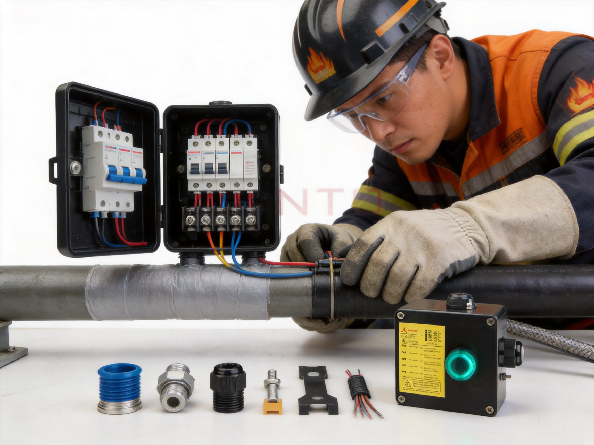
Routine maintenance should include visual inspection of the enclosure, cover, cable glands, plugs, bracket, grounding connection, and indicator window. Look for cracks, deformation, corrosion, loose hardware, damaged seals, and evidence of water ingress. Any defect that could affect the protection rating or grounding continuity should be corrected before the circuit is returned to service.
The cover should not be opened unnecessarily, particularly in hazardous areas. When it must be opened, follow the required isolation and permit procedures. After maintenance, inspect the gasket and cover screws, restore the enclosure carefully, and repeat the applicable electrical and protection checks.
The LED indicator should be compared with the measured electrical condition of the circuit. If the circuit is energized but the indicator is dark, the indicator module may require replacement. If the LED remains lit when the circuit is believed to be isolated, formal electrical testing must be used to confirm the actual state.
Grounding connections should be inspected for corrosion and mechanical looseness. Armored-cable installations should receive particular attention because the armor bonding path is an essential part of the protective system. Grounding continuity should be documented at commissioning and during scheduled inspection.
They are single-circuit power supply junction-box kits designed to connect power to compatible parallel industrial heating cables. They provide enclosure protection, terminals, cable sealing, mechanical support, and grounding provisions.
The E version uses an M25 cable-entry arrangement with a power-cable gland and plug. The EP version includes an M25 plug, a grounding plate, and an external grounding bolt, making it suitable for installations that use armored cables.
The product family is identified with CNEX, IECEx, ATEX, DNV, Baseefa, and EAC certification references. The exact model, certification marking, area classification, cable gland, and installation method must be verified before use in a hazardous area.
The supplied information states that the core sealing sleeve can be installed without a hot-air gun or spray lamp. This can simplify work in operating plants and reduce the need for hot-work procedures. Installers must still follow the approved installation instructions and site safety rules.
The listed maximum conductor size is 10 mm² for multi-strand conductors and 10 mm solid electrical building wire. The actual cable must also be compatible with the terminal, gland, heating cable, and local electrical regulations.
The E and EP versions are listed at a maximum of 254 Vac and 40 A heating-wire circuit current. The North American A version is listed at up to 277 Vac and 50 A. The complete heat-tracing system may have lower limits, so the heating cable and protective-device ratings must also be checked.
The optional LED provides a visual indication through a viewing window in the cover. It helps personnel identify the apparent energized state without opening the enclosure. It does not replace lockout, isolation, or electrical testing procedures.
The E and EP versions are listed with IP66/IP67 protection. The A version is listed with NEMA 4X protection. These ratings depend on correct assembly, suitable glands and plugs, proper cover installation, and compliance with the product instructions.
The supplied information identifies temperature ranges extending down to -50°C, with exact limits depending on the specific model and indicator version. The maximum pipeline temperature must be evaluated using the specifications of the companion heating cable and the complete system design.
No. It is designed for compatible parallel heating cables, including the listed UFA, UFB, UFC, UFO, and ABB series. The cable construction, terminal arrangement, current, voltage, and sealing requirements must be confirmed before installation.
The EP version includes a grounding plate and external grounding bolt. These components provide a defined arrangement for connecting and bonding cable armor, subject to the approved installation method and applicable electrical requirements.
Depending on the configuration, the kit may include the junction box, terminal blocks, indicator module for L versions, bracket, core sealing sleeve, yellow-and-green grounding sleeve, M25 gland, M25 plug, grounding plate and bolt, lubricant, and cable tie.
The product information states that the kits have basic specifications and can be customized and installed on-site. Customers should provide cable type, region, voltage, current, cable-entry details, insulation thickness, hazardous-area classification, and documentation requirements when requesting project support.
The MFS-100-L-E and MFS-100-L-EP single-circuit power supply junction boxes are purpose-designed accessories for industrial electric heat-tracing systems. Their strengths include a durable engineering-polymer enclosure, IP66/IP67 protection, silicone-rubber sealing, stainless-steel cover screws, application-specific terminals, optional LED indication, a bracket for a 100 mm insulation layer, and installation of the core sealing sleeve without flame or hot-air equipment.
The E and EP configurations provide practical choices for Eurasian-region installations, with the EP version adding a grounding plate and external grounding bolt for armored cables. The stated hazardous-area certifications and international approvals can support demanding industrial projects, provided that the exact model and installation conditions are correctly verified.
The manufacturer’s long-term focus on electric heating technology, reported quality-system certification, research activity, product-testing infrastructure, and broad industry experience provide an important foundation behind the accessory. For users, the value of the product lies not only in the enclosure itself but in the coordinated relationship between the junction box, heating cable, sealing system, grounding arrangement, and installation process.
When correctly selected, installed, tested, and maintained, the MFS-100 family can provide a reliable connection point for pipeline freeze protection, process temperature maintenance, tank heating, industrial heat tracing, and other applications where electrical safety and environmental protection are essential.
1. MFS-100 Product Specification, manufacturer-supplied technical document.
2. Product installation and accessory information for MFS-100 series single-circuit power supply junction boxes.
3. WAGO 284 Series terminal-block technical information.
4. IEC standards and guidance concerning electrical equipment for explosive atmospheres.
5. ATEX and IECEx principles for equipment used in hazardous areas.
6. International enclosure protection classifications for IP-rated equipment.
7. NEMA enclosure standards for industrial electrical equipment.
8. Industrial electric heat-tracing design, installation, inspection, and maintenance practices.
9. Manufacturer information concerning electric heating cable development, production, quality management, and testing capabilities.
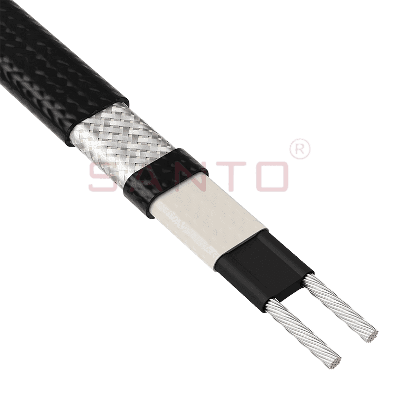
The SANTO UFA range of self-regulating heating cables is mainly used for frost protection of pipes and vessels but can also be used to maintain processes up to 65°C. These heating cables are available...
See Details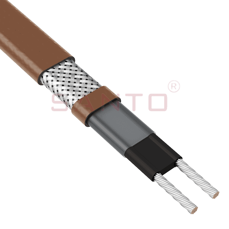
The SANTO UFB range of self-regulating heating cables is mainly used for frost protection of pipes and vessels requiring a higher power output than the UFA heating cables can supply. They can also be ...
See Details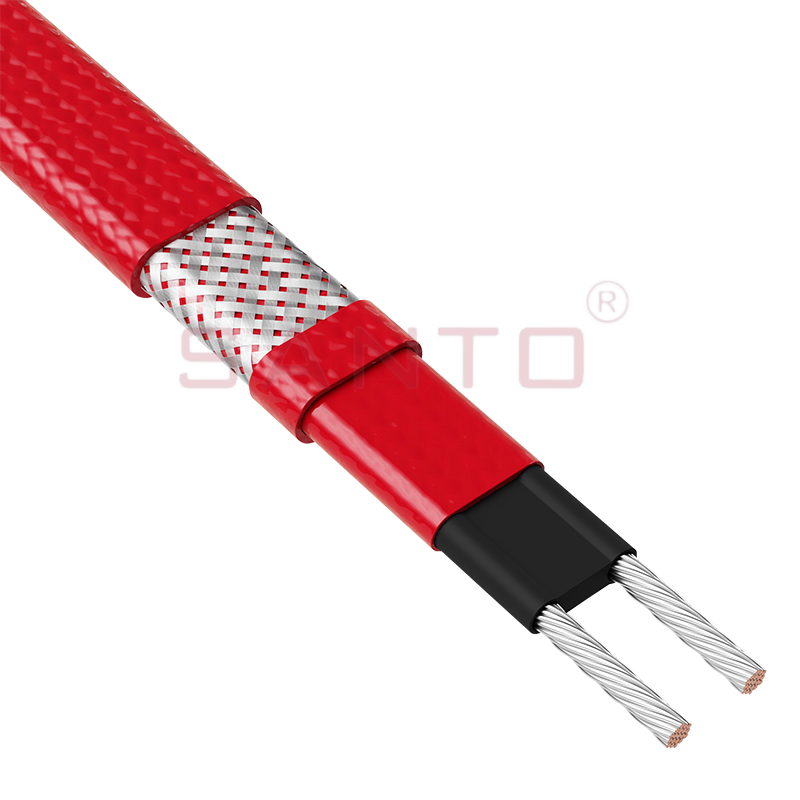
The SANTO UFC range of self-regulating heating cables is used for frost protection of pipes and vessels that require steam cleaning. They can also be used to maintain processes up to 121°C. These heat...
See Details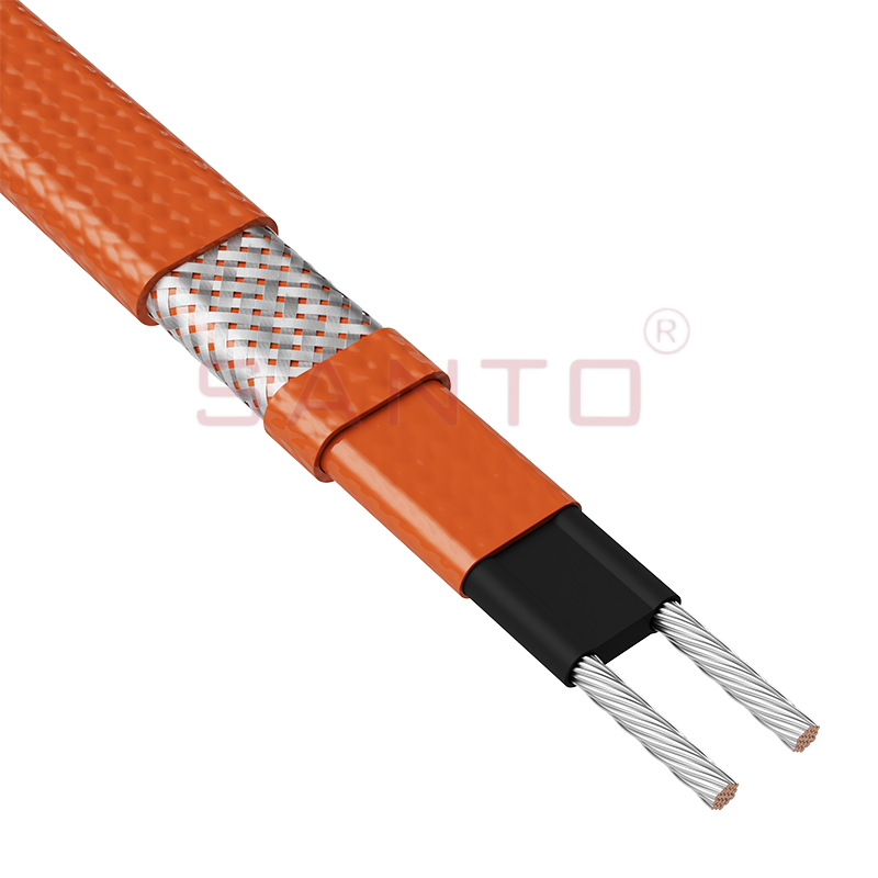
The SANTO UFO range of self-regulating heating cables is mainly used for frost protection of pipes and vessels that require steam cleaning . They can also be used to maintain processes up to 150°C. Th...
See Details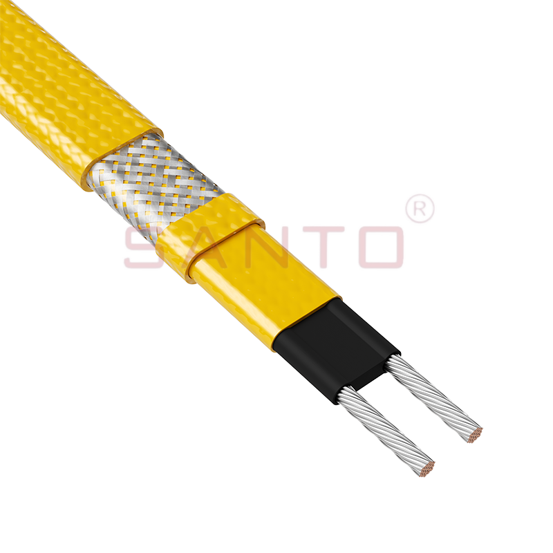
The SANTO UFD series of self-regulating heating cables are mainly used for freeze protection of pipes and vessels, but can also be used to maintain processes up to 200°C. These heating cables are avai...
See Details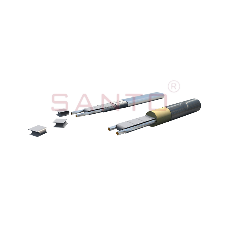
SANTO UFY heating wire is suitable for applications that maintain process temperatures up to 260 ℃ and can be steam blown; The self-regulating and parallel circuit heating wires of the UFY series are ...
See Details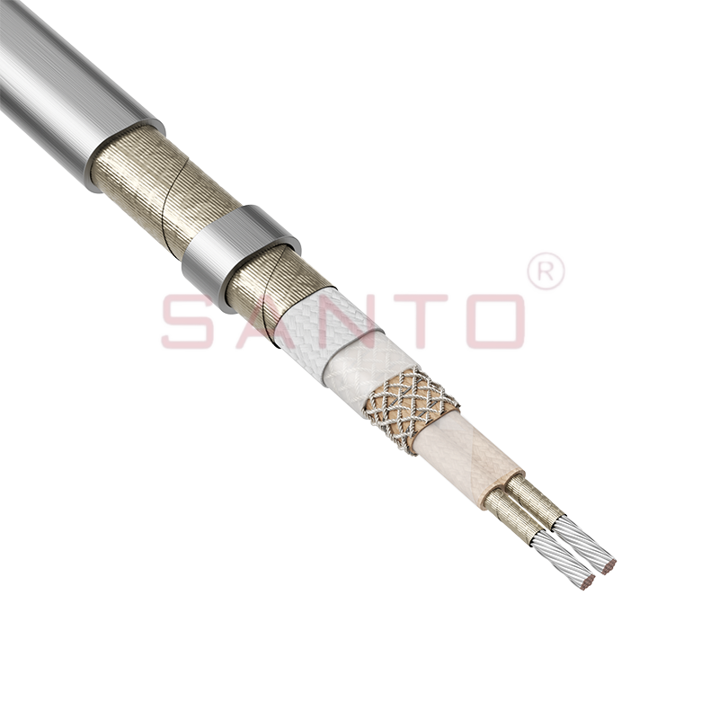
The SANTO UFM series self-regulating heating cables are mainly used for freeze protection of pipes and vessels, but can also be used to maintain processes up to 400°C. These heating cables are availab...
See Details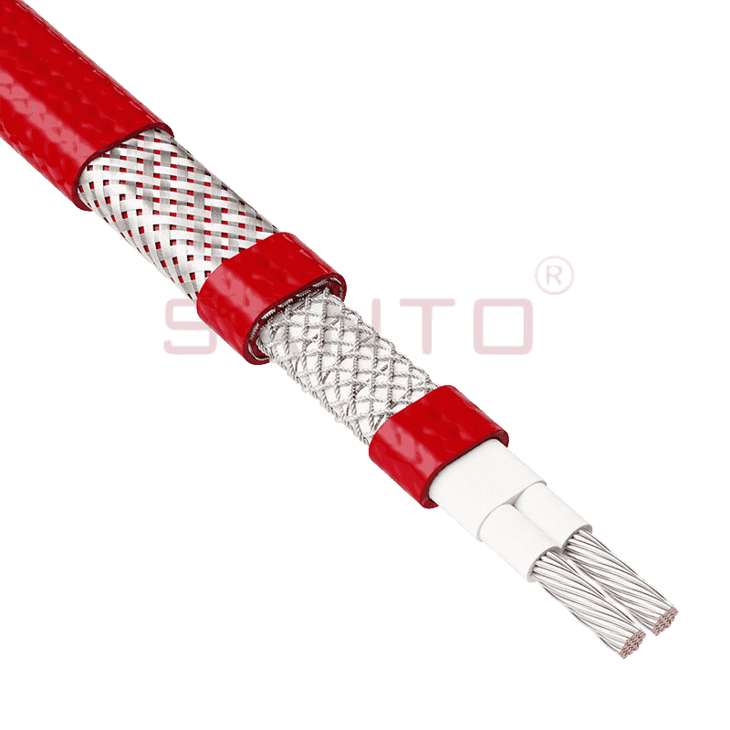
The SANTO ACC range of power-limiting heating cables is mainly used for temperature maintenance of processes and offers the advantage of a high power output at high temperatures which can reduce the n...
See Details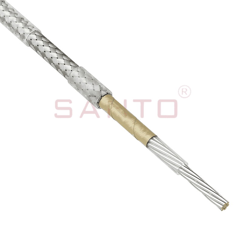
The stranded high temperature conductor is nickel plated to ensure a long life at elevated temperatures in corrosive environments. It is electrically isolated using an innovative sandwich construction...
See Details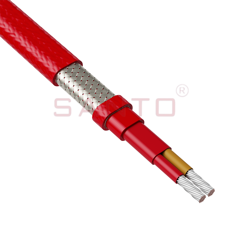
The stranded high temperature conductor is nickel plated to ensure a long life at elevated temperatures in corrosive environments. It is electrically isolated using an innovative sandwich construction...
See Details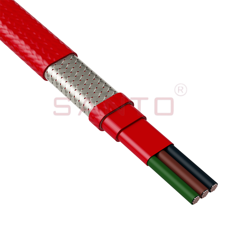
The stranded high temperature conductor is nickel plated to ensure a long life at elevated temperatures in corrosive environments. It is electrically isolated using an innovative sandwich construction...
See Details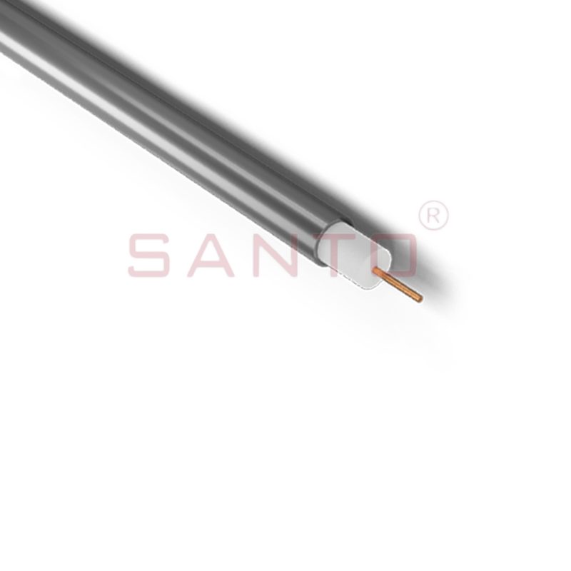
SANTO HAx mineral insulated (MI) Alloy 825 series heating cables are suitable for use in hazardous areas. They have been designed for use in freeze protection and temperature maintenance applications ...
See Details
Santo electric heating strips are widely used in key industries in China.

