 English
 English
 русский
 日本語
 Español
 中文简体

The SANTO UFA range of self-regulating heating cables is mainly used for frost protection of pipes and vessels but can also be used to maintain processes up to 65°C. These heating cables are available...
See Details
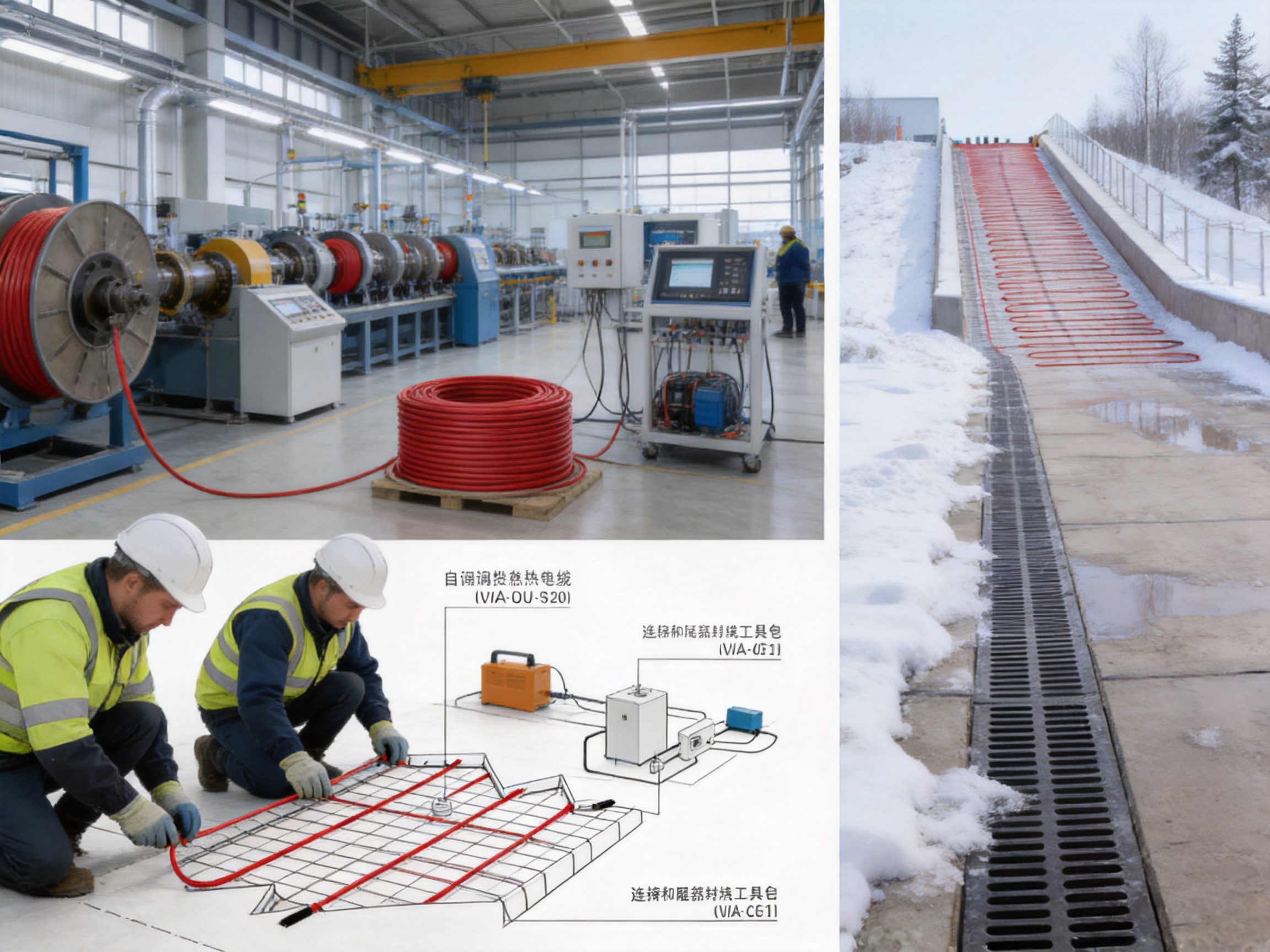
Snow and ice on roads, ramps, walkways, stairs, entrances, loading areas, and other exposed surfaces can create serious safety, access, and operational problems. Conventional snow removal depends on labor, vehicles, chemicals, or manually operated heating equipment. These methods can be costly, slow, environmentally undesirable, or unreliable during rapidly changing weather. A properly designed electric snow melting system provides a continuous and controlled method for reducing ice formation and removing snow from critical outdoor areas.
The SANTO UFP self-regulating heating and snow melting cable is designed for ground heat tracing applications where dependable winter protection is required. It can be installed beneath concrete, in sand and cement mixtures, or directly beneath asphalt when the installation design and cable specifications are properly matched to the project. Its flexible form supports irregular heating zones, ramps, lanes, driveways, walkways, stairs, and other surfaces where conventional heating layouts may be difficult to arrange.
The product is intended to work as part of a complete snow and ice melting solution. The heating cable is supported by an intelligent control approach, including the VIA-DU-20 control unit, which combines ground temperature, ground moisture, and ambient temperature information. Instead of operating only because the temperature has dropped below a fixed setting, the control system can activate heating when the conditions indicate the presence or likely formation of snow and ice. This operating principle can substantially reduce unnecessary energy consumption compared with basic constant-temperature control.
For contractors, system integrators, building owners, and industrial users, the key value of this solution is not simply the heating cable itself. The value comes from the combination of cable flexibility, field installation convenience, environmental durability, sensor-based control, manufacturing experience, and technical support. Together, these characteristics help create a practical system for protecting outdoor surfaces during freezing weather.
Content
The SANTO UFP self-regulating heating and snow melting cable is an electric heating product developed for road and ground snow melting applications. It is suitable for systems in which heat must be distributed below an exterior surface to melt snow, prevent ice accumulation, and improve pedestrian or vehicle safety.
The cable can be incorporated into several types of surface construction. Depending on the project design, it may be installed below concrete, within a prepared sand or cement layer, or beneath asphalt. The selected installation method must consider surface materials, required heating output, cable spacing, local weather, drainage, insulation, electrical loading, and the construction sequence. Proper engineering is essential to ensure that the heating system performs effectively without damaging the cable during installation.
Typical application areas include vehicle ramps, access lanes, driveways, roads, sidewalks, stairs, entrance areas, loading zones, bridge approaches, and other outdoor surfaces where snow and ice can interrupt normal use. It is particularly useful in locations where manual snow removal is difficult, where access must remain available, or where a slip-and-fall incident could cause significant financial or operational consequences.
The product is described as self-regulating because the heating behavior is designed to respond to temperature conditions along the cable. In a complete system, this characteristic can help reduce localized overheating risks and support more adaptable heat distribution than a simple fixed-output heating arrangement. However, self-regulating behavior does not replace system controls, electrical protection, correct spacing, or professional installation. The cable must always be selected and installed according to the applicable product documentation and local electrical requirements.
A snow melting installation normally consists of more than heating cable. It can include sensors, a control unit, an integrated control panel, power connections, end-seal or tail-end connection components, junction arrangements, electrical protection, and a suitable surface construction. The SANTO solution is intended to support this complete-system approach rather than treating the cable as an isolated component.
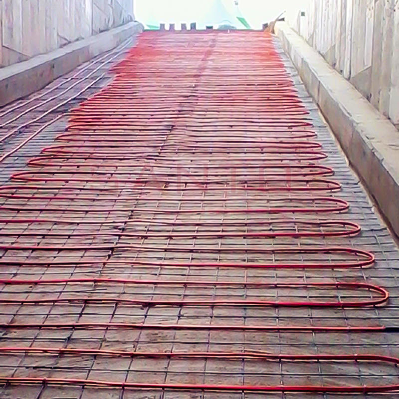
SANTO UFP Self regulating heating and snow melting cable
Freezing precipitation can create hazards within a short period of time. A wet surface may become slippery when temperatures fall, while compacted snow can form a hard layer that is difficult to remove manually. Vehicle ramps may lose traction, stairs may become dangerous, and emergency or service access may be restricted. Even a small amount of ice at an entrance can create a serious liability concern.
Traditional snow removal methods have important limitations. Manual clearing requires personnel to be available during storms and may need to be repeated several times. Snowplows and mechanical equipment may not be suitable for narrow walkways, stairs, loading zones, or sensitive surfaces. Chemical deicers can damage concrete, metal, vegetation, and drainage systems when used excessively. Salt and other chemicals may also be undesirable around buildings, industrial equipment, water systems, and environmentally sensitive areas.
Electric snow melting addresses these limitations by placing the heat source beneath the surface. When the control system detects suitable snow or ice conditions, the cable warms the surface and supports the melting process. Water can then be directed toward properly designed drainage points. The system does not eliminate the need for sound drainage, surface design, or weather planning, but it provides an automatic method for controlling freezing conditions at selected high-priority locations.
Permanent ground heat tracing is especially valuable in locations where safety and availability are more important than the cost of occasional manual clearing. Examples include hospital entrances, fire access routes, commercial delivery ramps, public stairs, residential driveways, airport or transport areas, industrial yards, and facility access points. It can also reduce the need to store snow removal equipment or maintain a large emergency workforce.
One of the principal advantages of the system is its compatibility with intelligent control. The VIA-DU-20 control unit is described as using a sensor block combination capable of measuring ground temperature, ground humidity, and ambient wall temperature. These measurements work together to determine whether the surface is experiencing conditions associated with snow, ice, or water.
A conventional temperature-only system may start whenever the measured temperature falls below a selected value. This approach can cause heating to operate during cold but dry conditions, even when there is no snow or water on the ground. It may also continue operating longer than necessary after the surface has dried. Every unnecessary operating hour increases power consumption and operating cost.
The intelligent control principle is different. It can remain inactive when the surface is cold but dry, then activate heating when moisture and temperature conditions indicate that snow or ice may be present. This reduces operation during periods when heating provides little practical benefit. The manufacturer states that energy savings of up to 80 percent may be achieved compared with standard constant-temperature control. Actual savings depend on climate, surface construction, heating design, weather patterns, operating settings, insulation, drainage, and the performance of the complete installation.
Sensor-based control also makes the heating system more responsive to real conditions. Outdoor weather is not determined by air temperature alone. A surface may be wet before freezing, snow may begin falling at a temperature near the freezing point, and conditions can vary between shaded and exposed areas. Combining temperature and moisture information gives the control unit more useful information than a single temperature set point.
From an operating perspective, intelligent control provides three important benefits:
First, it reduces heating operation during cold and dry periods. Second, it helps activate the system when moisture and freezing conditions occur together. Third, it can help the system stop or reduce operation when the snow or ice event has passed and the surface no longer requires heating.
Energy efficiency should always be evaluated at the system level. Cable spacing, installed wattage, surface insulation, sensor location, control settings, and drainage all influence the final result. An efficient control unit cannot compensate for incorrect installation or a poorly designed heated area. When the heating output and control strategy are properly coordinated, however, intelligent sensing can be a major advantage over basic fixed-temperature operation.
Self-regulating heating cable technology is well suited to applications in which environmental conditions may vary along the length of the heated surface. Outdoor surfaces can experience differences caused by shade, wind, nearby buildings, drainage, traffic, snow accumulation, and construction materials. A self-regulating cable is designed to adjust its heat-producing behavior in response to temperature conditions along its length.
This characteristic can make the system more adaptable than a simple constant-output arrangement. It may help limit excessive heat production in warmer sections while maintaining useful heating behavior in colder sections. It also supports the practical operation of a system exposed to changing weather conditions.
Self-regulation should not be confused with unlimited temperature control or automatic protection against every installation error. The cable must still be installed at the correct depth and spacing. It must not be cut, overlapped, sharply bent, crushed, or exposed to conditions outside its rated application. Electrical protection and control equipment remain necessary. Professional installation and commissioning are essential to obtain safe and reliable performance.
The SANTO UFP design also supports practical field work. The heating wire can be cut as required and connected at the tail end on site, while factory-supplied tail-end connection units are available for suitable installation arrangements. This flexibility can be useful when a heated zone does not match a standard rectangular layout. Contractors can adapt the cable path to the actual dimensions of ramps, entrances, steps, and irregular surfaces rather than forcing the project into a rigid preassembled format.
Many outdoor areas are not simple rectangles. A vehicle ramp may narrow near a gate, a driveway may curve around a building, and a stairway may include landings or changes in width. A walkway may have columns, drainage channels, expansion joints, or other obstacles. An effective snow melting cable must be capable of being arranged around these features while preserving the intended heating pattern.
The flexible design of the SANTO system is intended to simplify the heating of complex areas. Ramps, irregularly shaped entrances, lanes, and ground sections can be planned according to the actual surface geometry. The cable layout can be developed to provide the required coverage in traffic lanes, wheel paths, pedestrian paths, stair treads, and other priority zones.
Flexible design also supports project-specific energy planning. Not every portion of a property needs the same heating level. A design may prioritize the steepest section of a ramp, the most frequently used entrance, or a narrow pedestrian route while leaving low-priority areas unheated. This can reduce the total installed load and improve the economic value of the project.
Before installation, the heated area should be divided into practical zones. Each zone can be reviewed for surface type, expected use, moisture exposure, snow accumulation, drainage, cable length, power supply, and control requirements. A clear zoning plan helps installers avoid crossing boundaries, exceeding circuit capacity, or placing cable in areas where heat is not needed.
The ability to adapt the cable layout is one of the system’s advantages over inflexible preformed solutions. Preassembled mats can be convenient for regular floor sections, but they may be difficult to use around curves, corners, ramps, steps, or irregular entrances. A cable-based system allows the installer to respond to the actual construction geometry.
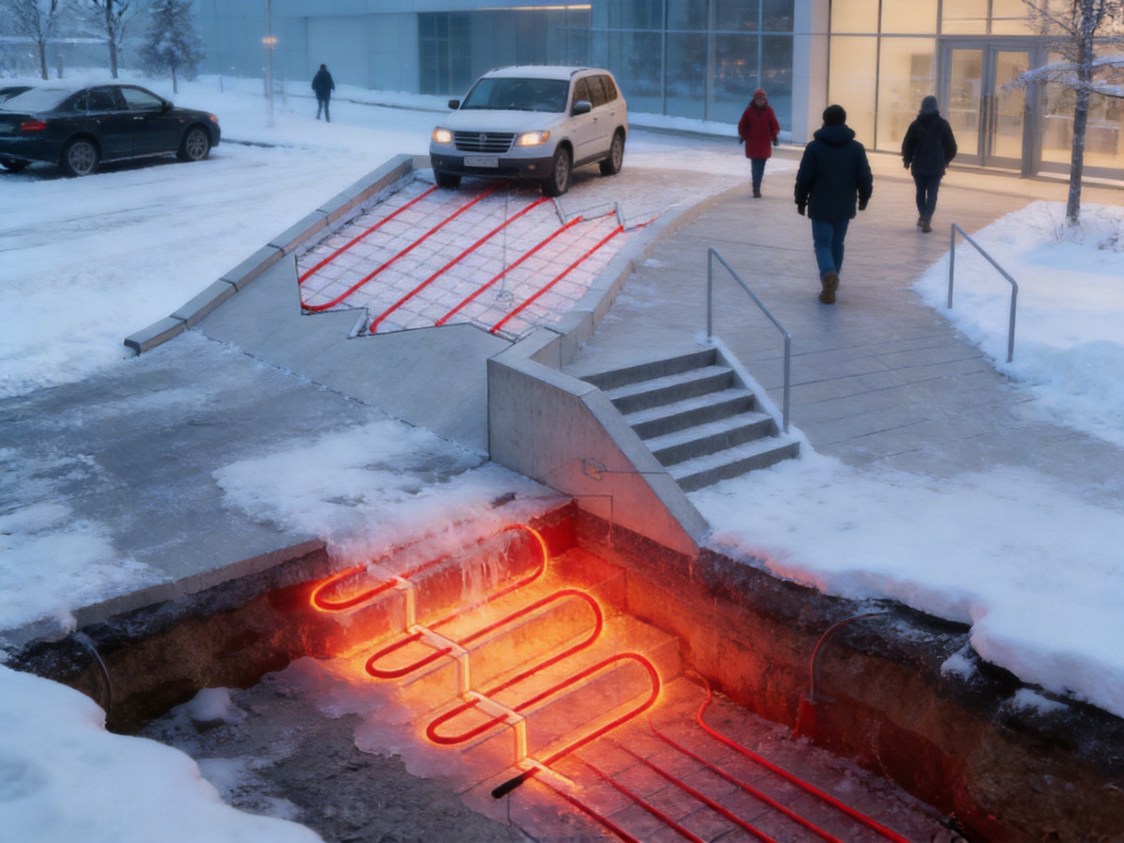
The product is designed for demanding installation environments, including cement, sand, and hot-poured asphalt applications when the installation follows the correct technical requirements. These environments can expose heating cable to mechanical stress, moisture, compression, chemical interaction, and elevated temperatures. A durable cable construction and a controlled installation process are therefore essential.
For concrete applications, the cable layout is normally secured at the planned position before the concrete is placed. The cable must remain at the designed spacing and depth during pouring and vibration. It should not be dragged, sharply bent, crushed by reinforcement, or damaged by construction tools. The installer should also verify that the cable does not interfere with expansion joints or other structural details unless the design specifically addresses those locations.
For sand-bed installations, the prepared base should be level and free of sharp objects that could damage the cable. The cable must be positioned so that it remains stable during the placement of the upper surface layer. Sand and bedding materials should be installed without displacing or compressing the cable beyond acceptable limits.
Asphalt installations require special care because hot asphalt can expose the cable to high temperatures and mechanical forces. The cable and all accessories must be confirmed as suitable for the specific paving process. Placement should be planned with the paving contractor so that the cable is not cut by equipment, pulled out of position, or subjected to unapproved temperature exposure. The use of hot-poured asphalt demonstrates the need for a system developed for harsh installation conditions, but it does not remove the need to follow the product’s technical limitations.
Each installation should include inspection and electrical testing before, during, and after surface construction. Resistance, insulation integrity, continuity, connection quality, and sensor operation should be checked according to the applicable technical documentation. Test results should be recorded for future maintenance and warranty reference.
Construction coordination is one of the most important factors in a ground heating project. The electrical contractor, civil contractor, paving team, control installer, and project engineer should understand the cable layout and protect it throughout construction. Marking cable routes, documenting connection points, and photographing the installed system before covering it can significantly improve future serviceability.
A snow melting cable performs best when it is integrated into a complete ground heat tracing system. The system may include heating cable, sensor assemblies, an intelligent control unit, an integrated control panel, electrical protection, connection components, and suitable surface construction.
The control panel provides a central location for power distribution, switching, protection, and control connections. Depending on the project, the panel may include contactors, circuit protection, residual-current protection, control relays, indicator devices, and other equipment required by local standards. Panel design should be based on the connected load and the operating environment.
Ground and ambient sensors must be installed in representative locations. A sensor placed in a sheltered area may not accurately represent a ramp exposed to wind and precipitation. A sensor installed where water cannot reach it may fail to provide useful moisture information. Sensor placement should therefore be considered during the civil and electrical design stages rather than treated as an afterthought.
Connection and tail-end components are also important. Poorly sealed connections can allow moisture penetration, while badly positioned components can make inspection or replacement difficult. Factory-supplied connection units can simplify field assembly and help improve consistency when used according to the manufacturer’s instructions.
A complete system should also consider drainage. Melting snow creates water, and that water must have a path away from the heated surface. Drains, channels, slopes, and discharge locations should be reviewed for freezing risk. If the melted water flows into an unheated area and refreezes, the hazard may simply move rather than disappear.
| System element | Primary function | Design consideration |
|---|---|---|
| Self-regulating heating cable | Produces heat below the protected surface | Length, spacing, installed output, bending limits, and surface compatibility |
| Ground temperature sensor | Measures surface or ground temperature | Representative location and protection from construction damage |
| Ground moisture sensor | Detects water, wet snow, or moisture conditions | Direct exposure to the relevant surface conditions |
| Ambient temperature sensor | Provides surrounding temperature information | Placement away from artificial heat sources and sheltered pockets |
| Intelligent control unit | Coordinates sensor data and heating operation | Correct settings, zoning, commissioning, and maintenance access |
| Integrated control panel | Distributes power and provides electrical protection | Load calculation, enclosure rating, local code compliance, and service space |
| Tail-end and connection units | Complete and protect cable circuits | Correct sealing, mechanical protection, and documented connection points |
| Surface and drainage structure | Transfers heat and removes meltwater | Material compatibility, slope, drainage capacity, and construction quality |
Several features distinguish this solution from a basic constant-temperature electric heating system.
A basic system may rely only on a temperature set point. The SANTO solution is compatible with a control method that combines temperature and moisture information. This allows heating to be linked more closely to actual snow and ice conditions instead of cold weather alone.
Because heating can remain off during cold and dry periods, the system may reduce wasted energy. The manufacturer states that the intelligent control approach can save up to 80 percent compared with standard constant-temperature control. The precise result must be verified for each project, but the control principle provides a strong basis for reducing unnecessary runtime.
A cable layout can be designed around curves, ramps, steps, entrances, and other complex shapes. This is more adaptable than a rigid heating format intended only for regular surfaces.
The system is designed for installation environments that may include cement, sand, and hot-poured asphalt. This expands the range of possible applications when the cable, accessories, surface materials, and installation method are properly coordinated.
The ability to cut the heating wire as needed and complete suitable tail-end connections on site can help contractors respond to actual project dimensions. Factory-supplied connection units can further simplify installation and improve field convenience.
The product is supported by control units, sensors, panels, and accessories rather than being presented only as a length of heating cable. A complete-system approach can reduce compatibility problems and help simplify procurement, installation planning, commissioning, and service.
The manufacturer, Santo Thermal Control Technology Co., Ltd., has developed its business around electric heating and thermal control products. Its product range includes automatic temperature-control heating belts, self-limiting heating belts, heat tracing belts, constant-power heating belts, silicone rubber heating products, glass fiber heating products, MI cables, snow melting cables, electric hot wires, and related accessories.
This product diversity is important because snow melting projects often exist alongside other thermal management requirements. A supplier with experience in multiple heating technologies can better understand differences in temperature control, cable construction, insulation, connection methods, environmental resistance, and application-specific design.
The company’s history includes the establishment of an electric heating instrument factory in 2000, ISO9001:2000 quality system certification in 2002, and the creation of an irradiation center in 2013. Irradiation processing is used in certain cable manufacturing applications to improve material performance and support consistent production, although the exact process used for a specific product should be confirmed in the product’s technical documentation.
The company reports that it has invested in new product development, technology guidance, scientific management, product quality, and after-sales service. It also reports cooperation in product research with Harvard University in the United States and the development of patented heating technologies. These activities indicate an emphasis on engineering development rather than simple commodity assembly.
In 2014, the company’s founder developed a self-limiting temperature nano far-infrared heater for high-temperature pipeline heating and tracing. In 2017, the founder developed a carbon fiber parallel heating cable and obtained multiple invention patents. These developments reflect experience in self-regulating and specialized heating technologies that are relevant to the design of modern thermal control products.
The company states that it has passed ISO9001 quality system certification and that its products have obtained national CCC certification. Certification requirements and product applicability should always be checked for the specific model, market, and installation. Nevertheless, a documented quality system can support more consistent manufacturing, inspection, process control, corrective action, and customer service.
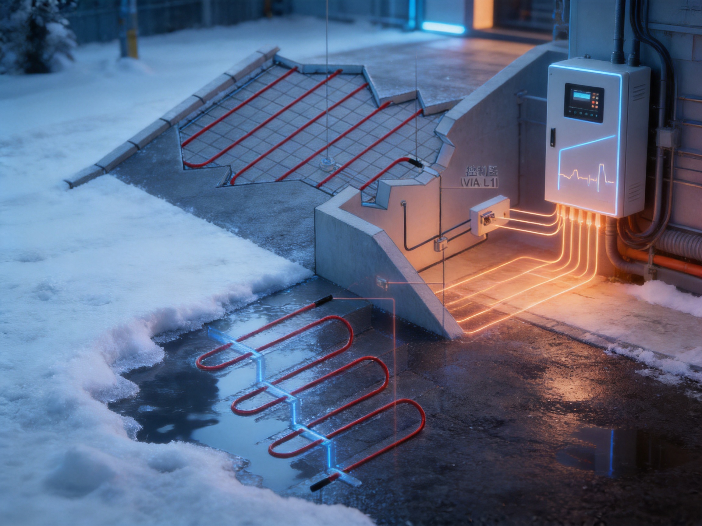
Reliable snow melting cable begins with controlled raw materials and continues through conductor production, insulation, jacket application, resistance testing, connection assembly, final inspection, and packaging. The exact process varies according to the cable design, but each stage can affect long-term performance.
Conductors must maintain consistent electrical characteristics along the cable length. Variations in conductor dimensions or resistance can create uneven output and complicate circuit design. Insulating materials must provide suitable dielectric strength, flexibility, and resistance to the expected thermal and environmental conditions. Outer layers must protect the cable during handling, installation, and service.
Manufacturing controls should include material verification, dimensional checks, electrical testing, visual inspection, and traceability. Connection components require special attention because they form part of the moisture barrier and mechanical termination. A high-quality cable can still fail if its field connections are poorly assembled or inadequately sealed.
For a supplier serving international markets, production capacity and quality consistency are also important. The company reports more than 35 years of industry experience, annual output exceeding 10,000 units or products, more than 2,000 distributors, and business coverage in more than 85 areas. These figures indicate a broad commercial presence, although buyers should request current production data and model-specific references when evaluating a project.
The company has also reported the establishment of a new factory and product simulation testing laboratory following additional land acquisition in 2022. A simulation and testing environment can support product verification under controlled conditions, including thermal behavior, mechanical stress, electrical performance, and application-specific evaluation. Test capability is especially valuable for products used in concrete, asphalt, industrial, and outdoor environments.
The reported establishment of a factory in Russia in 2023 reflects an effort to expand production and market presence. For international customers, regional manufacturing or distribution capability can support shorter supply routes, local service coordination, and improved response to project requirements. The actual availability of regional support should be confirmed before placing an order.
A successful snow melting project begins with a proper survey. Engineers should identify the exact area requiring protection, the expected snow and ice conditions, the surface construction, the available electrical supply, the drainage route, and the consequences of system downtime.
The following design questions should be addressed:
What portion of the site must remain clear during snowfall? Is the objective complete snow removal, ice prevention, or improved traction? What is the design minimum temperature? How much snow or ice is expected? Is the area exposed to wind or sheltered by surrounding buildings? Will vehicles, pedestrians, or heavy equipment cross the surface? What type of concrete, asphalt, sand bed, or paving system will be used?
The heated area should then be divided into zones based on use and electrical requirements. Separate zones can allow the operator to heat only the necessary areas. For example, a facility may prioritize a steep ramp and main entrance while using a lower operating priority for a rarely used service lane.
Cable spacing should be determined according to the required heating output and surface construction. Closer spacing generally increases heat density, while wider spacing reduces installed cable length but may reduce the uniformity or intensity of heating. The correct balance depends on climate, surface loss, insulation, and design objectives.
Sensor locations must be selected to reflect actual surface conditions. Sensors should not be placed directly above artificial heat sources, under roof overhangs that block precipitation, or in locations that remain permanently dry while the protected area becomes wet. Clear installation documentation should identify each sensor location and its associated control zone.
Electrical calculations should include circuit load, voltage, startup behavior where applicable, protective devices, residual-current protection, cable routes, panel capacity, and emergency isolation. Local electrical regulations and project-specific safety requirements must be followed. The system should be commissioned by qualified personnel.
Before installation, the installer should inspect the cable, confirm the model and length, review the layout, and verify that all accessories are available. Any visible damage, incorrect labeling, or mismatch between the delivery and the design should be resolved before the cable is placed.
The surface should be prepared according to the selected construction method. Sharp debris, standing water, unstable bedding, and obstructions should be removed. Cable routes should be marked, and the planned spacing should be checked against the drawing.
The cable should be fixed securely enough to prevent movement during the next construction stage. Bends must remain within the permitted radius, and overlapping or crossing should be avoided unless explicitly allowed by the product design. The cable should not be placed beneath permanent fixtures that may prevent heat transfer or create unwanted temperature concentration.
After positioning, the installer should perform the required electrical tests and record the results. The same testing should be repeated after the surface layer has been installed. If a test result changes unexpectedly, work should stop until the cause is identified. Covering a damaged cable can make repair expensive and disruptive.
Connection and tail-end units should be installed in accessible or properly protected locations. Sealing must be completed according to the manufacturer’s instructions. The installer should document connection points, cable routes, circuit identification, sensor positions, and test results.
Once the surface construction is complete, the control panel and sensors can be connected. The control unit should be programmed according to the application, local climate, and owner’s operating requirements. Commissioning should verify temperature sensing, moisture detection, automatic activation, shutdown behavior, manual override, alarm functions, circuit protection, and any communication or indication features included in the control panel.
The system should not be placed into normal operation until the surface materials have reached the required curing or installation condition. Premature heating can affect concrete curing, asphalt behavior, sealants, or other construction materials. The project engineer and surface contractor should establish the appropriate commissioning schedule.
Although an embedded heating cable is normally protected after installation, the complete system should receive periodic inspection. The control panel should be checked for signs of moisture, overheating, loose terminals, corrosion, or damaged enclosures. Protective devices should be tested according to applicable requirements.
Sensors should be inspected to ensure that they remain exposed to representative conditions and have not been covered, blocked, damaged, or relocated. Drainage points should be kept clear so that meltwater does not accumulate and refreeze.
Before the winter season, the operator should test the system under controlled conditions. This may include checking sensor response, control logic, indicator functions, manual operation, circuit continuity, and insulation resistance. Testing should be performed by qualified personnel and should follow the manufacturer’s recommendations.
Maintenance records should include test dates, measured values, control settings, repairs, alarms, and observations. Good records help identify gradual changes before a major failure occurs. They also provide useful information if the surface must later be repaired or modified.
Surface renovations require particular care. Drilling, cutting, coring, resurfacing, or installing anchors can damage embedded cable. The original as-built drawings, photographs, and cable route records should be reviewed before any work begins. If documentation is incomplete, cable detection and electrical investigation may be necessary.
Ramps are among the most important snow melting applications because vehicles can lose traction while ascending or descending. A heated ramp can reduce snow accumulation and improve access during freezing weather. The design should consider wheel paths, turning areas, drainage, slope, and the possibility of heavy vehicle loading.
Pedestrian areas may require a lower heating load than vehicle ramps, but they can present a high safety risk. Heated walkways and entrances can help reduce slippery conditions at locations with frequent foot traffic. Door thresholds, shaded sections, and areas where meltwater may collect should receive special attention.
Outdoor stairs are difficult to clear mechanically and can become dangerous when covered by compacted snow or ice. Cable layouts can be designed for stair treads, landings, and approach paths. The installer must ensure that the cable remains at the correct depth and does not interfere with structural reinforcement, nosings, expansion joints, or surface finishes.
Factories, warehouses, logistics facilities, and commercial buildings may need reliable access for employees, deliveries, emergency vehicles, and maintenance personnel. Snow melting can be concentrated in loading ramps, dock approaches, gate areas, and frequently used routes. Intelligent zoning allows the operator to focus energy on the most important locations.
Road sections may require a larger installed load and more complex control arrangement. The design should consider lane width, traffic loading, pavement structure, drainage, expansion joints, repair access, and the availability of electrical power. A staged installation may be appropriate for large areas.
Electric snow melting systems consume energy, so sustainability depends on responsible design and control. The intelligent sensor approach helps reduce operation during periods when snow melting is unnecessary. Zoning can further reduce energy use by limiting heating to priority areas.
Surface insulation and proper drainage also influence efficiency. Heat loss into the ground can increase required output, while standing water can increase the duration of operation. A well-designed surface transfers useful heat upward and moves meltwater away efficiently.
The use of heating rather than chemical deicers may reduce salt-related damage to concrete, vehicles, landscaping, and drainage systems. It may also reduce the need for repeated mechanical snow removal in sensitive or inaccessible locations. The environmental outcome depends on the electricity source, system design, operating schedule, and maintenance practices.
Owners should compare the full life-cycle cost rather than only the initial purchase price. Relevant factors include cable and control equipment, installation labor, civil work, electrical upgrades, seasonal energy consumption, maintenance, snow removal labor, chemical use, safety incidents, and operational downtime.
Snow melting cable is an embedded product that can be difficult and expensive to replace after surface construction. Selecting a manufacturer with established heating technology experience can therefore reduce project risk. Experience supports better understanding of insulation systems, resistance control, connection reliability, environmental exposure, testing, and technical documentation.
SANTO’s reported experience covers more than three decades of electric heating development and manufacturing. Its portfolio includes multiple heating technologies used in pipeline tracing, antifreeze protection, deicing, industrial heating, geothermal cultivation, construction, solar applications, and other thermal management fields.
The company’s stated capabilities include research, design, production, manufacturing, distribution, and after-sales service. This integrated structure can be beneficial for OEM and ODM customers seeking customized cable lengths, application-specific assemblies, control solutions, or private-label products. Customization should be evaluated through technical drawings, samples, testing requirements, minimum order quantities, and quality agreements.
International customers may also benefit from the company’s reported certifications, distributor network, product development history, and market experience. Buyers should request current certificates, factory audit information, test reports, product datasheets, and references relevant to the intended application before final approval.
Before purchasing a self-regulating snow melting cable, the customer should confirm the required heating area, surface type, cable length, circuit voltage, control method, sensor requirements, connection accessories, and installation environment.
The following documentation is recommended:
Product data sheet and installation manual.
Rated electrical characteristics and permitted operating conditions.
Applicable certifications and quality documentation.
Recommended cable spacing and installation depth.
Minimum bending radius and restrictions on cutting or overlapping.
Connection and tail-end termination instructions.
Compatibility information for concrete, sand, asphalt, and other surface materials.
Control unit wiring and sensor installation instructions.
Factory inspection and test records where required.
Warranty terms, technical support arrangements, and replacement procedures.
The buyer should also determine whether the project requires standard products or customized assemblies. Custom cable production may be valuable for unusual lengths, special connections, integrated accessories, or OEM branding, but customization should be supported by an approved technical specification.
No snow melting system can replace sound engineering. Heating output must be sufficient for the local climate and application. Poor drainage, excessive snow accumulation, inadequate power, incorrect sensor placement, or construction damage can reduce performance regardless of cable quality.
The stated potential energy saving of up to 80 percent is a comparative manufacturer claim based on intelligent control versus standard constant-temperature control. It should not be treated as a guaranteed result for every installation. Customers should evaluate energy performance using local weather data, operating schedules, surface conditions, and measured system performance.
The system should not be used outside its specified temperature, electrical, mechanical, or environmental limits. Installation, electrical connection, testing, and commissioning should be completed by qualified professionals. Local codes, regulations, building requirements, and safety standards take priority over general product descriptions.
Self-regulating performance does not mean that the cable may be installed without spacing rules or circuit protection. The cable must not be damaged during paving, concrete placement, drilling, or later surface repair. Complete records and careful coordination are essential.
The cable is designed to provide electric heat beneath outdoor surfaces so that snow and ice can be melted or prevented from accumulating. Typical locations include ramps, roads, driveways, walkways, stairs, entrances, and other areas where freezing conditions create access or safety problems.
The system is designed for demanding installation conditions, including hot-poured asphalt applications when the cable and installation method are suitable. The project team must confirm the permitted temperature, paving process, protection requirements, and installation instructions before construction.
The control system combines temperature and moisture information rather than relying only on a fixed temperature setting. It can remain off during cold, dry conditions and activate when water, snow, or ice conditions are detected. This reduces unnecessary operating time. Actual savings vary by project.
The described control arrangement uses a combination of ground temperature, ground humidity, and ambient temperature sensing. Correct sensor placement is essential because the sensors must represent the real conditions of the protected surface.
Yes. The flexible cable layout can be designed for ramps, curved lanes, irregular entrances, stairs, and other non-rectangular areas. The layout must follow the required spacing, bending, electrical, and installation rules.
The product information states that the heating wire can be cut as needed and connected at the tail end on site, with factory-supplied tail-end connection units also available. Cutting and termination must be performed only according to the approved installation procedure.
A self-regulating cable still requires suitable control and electrical protection. The intelligent control unit helps determine when heating should operate, while the panel provides power distribution and protective functions. Self-regulation does not replace proper control design.
Applications include concrete, sand-bed construction, asphalt, roads, ramps, lanes, walkways, stairs, and other outdoor ground surfaces. Compatibility depends on the specific cable model, installation conditions, surface material, and project design.
No. Melting snow produces water, so the surface must have an appropriate slope, drainage channel, or discharge route. Without drainage, meltwater may collect and refreeze in another location.
Customers should provide the heated area dimensions, surface construction, local climate, desired application, power supply, control preference, installation method, cable length requirements, project schedule, and any certification or customization requirements.
The manufacturer reports more than 35 years of electric heating industry experience, ISO9001 quality system certification, a broad heating product portfolio, research and development activity, production facilities, product testing capability, international market experience, and technical support for customized heating solutions.
Maintenance should include inspection of the control panel, sensors, protective devices, connections, drainage, and operating settings. Pre-season testing and documented electrical measurements can help confirm readiness before freezing weather begins.
The SANTO UFP self-regulating heating and snow melting cable provides a flexible foundation for protecting roads, ramps, walkways, stairs, and other outdoor surfaces from snow and ice. Its principal advantages are the ability to adapt to irregular heating zones, suitability for demanding installation environments, field connection flexibility, and compatibility with an intelligent control strategy.
The VIA-DU-20 control approach is particularly important because it links system operation to temperature and moisture conditions. By avoiding unnecessary heating during cold but dry periods, it can reduce energy consumption and operating costs compared with standard constant-temperature control. The manufacturer states that savings of up to 80 percent may be achieved under suitable conditions, although every project requires its own evaluation.
The system’s effectiveness depends on more than cable selection. Correct engineering, cable spacing, sensor placement, electrical protection, surface construction, drainage, commissioning, and maintenance all influence the final result. When these elements are coordinated, electric ground heat tracing can provide reliable winter protection while reducing dependence on manual snow removal and chemical deicers.
The manufacturer’s long-term focus on electric heating technology, broad product range, reported quality certifications, research activity, testing capability, and international business experience further supports the product’s position as a practical solution for OEM, ODM, commercial, industrial, and infrastructure applications. For projects where safety, access, and winter reliability are priorities, a complete self-regulating snow melting system deserves consideration during the early design stage.
1. SANTO Thermal Control Technology Co., Ltd., product information for the UFP self-regulating heating and snow melting cable.
2. SANTO Thermal Control Technology Co., Ltd., technical information for the VIA-DU-20 intelligent snow melting control unit.
3. SANTO Thermal Control Technology Co., Ltd., company profile and electric heating product portfolio.
4. ISO 9001, Quality Management Systems: Requirements.
5. General engineering practices for electric floor, ground, and snow melting heating systems.
6. Applicable local electrical codes and regulations for embedded heating cables, residual-current protection, control panels, and outdoor installations.
7. Project-specific civil engineering requirements for concrete, asphalt, sand-bed construction, surface drainage, expansion joints, and winter maintenance.
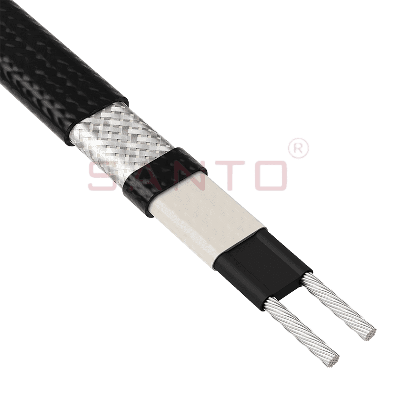
The SANTO UFA range of self-regulating heating cables is mainly used for frost protection of pipes and vessels but can also be used to maintain processes up to 65°C. These heating cables are available...
See Details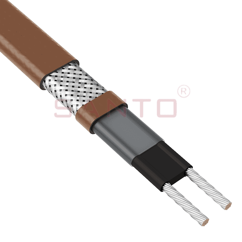
The SANTO UFB range of self-regulating heating cables is mainly used for frost protection of pipes and vessels requiring a higher power output than the UFA heating cables can supply. They can also be ...
See Details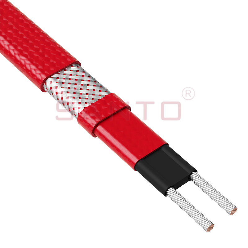
The SANTO UFC range of self-regulating heating cables is used for frost protection of pipes and vessels that require steam cleaning. They can also be used to maintain processes up to 121°C. These heat...
See Details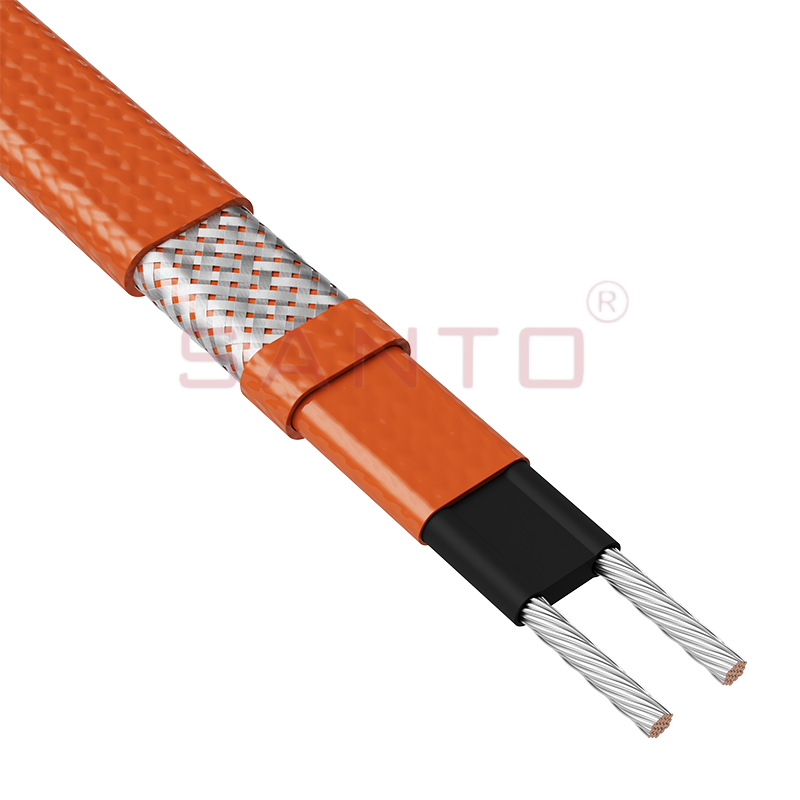
The SANTO UFO range of self-regulating heating cables is mainly used for frost protection of pipes and vessels that require steam cleaning . They can also be used to maintain processes up to 150°C. Th...
See Details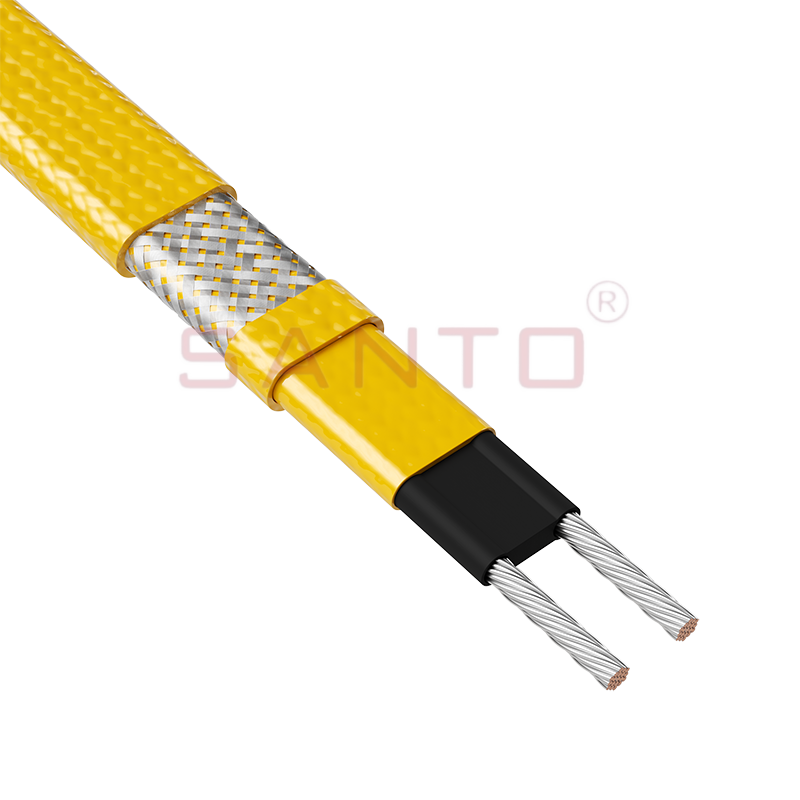
The SANTO UFD series of self-regulating heating cables are mainly used for freeze protection of pipes and vessels, but can also be used to maintain processes up to 200°C. These heating cables are avai...
See Details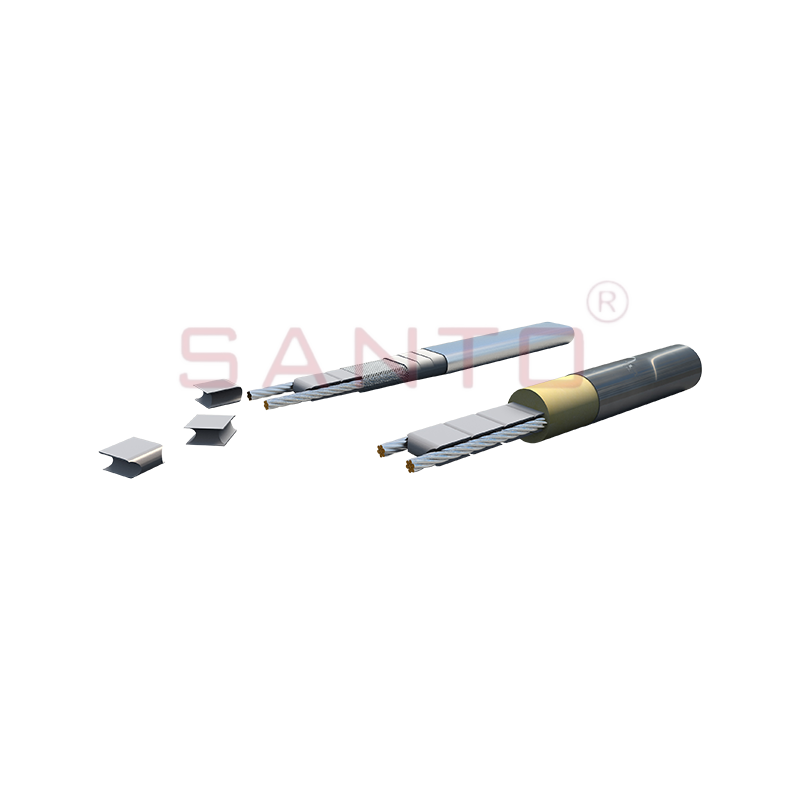
SANTO UFY heating wire is suitable for applications that maintain process temperatures up to 260 ℃ and can be steam blown; The self-regulating and parallel circuit heating wires of the UFY series are ...
See Details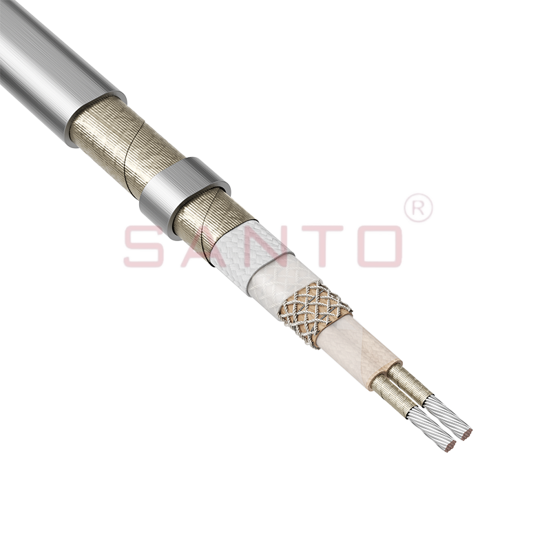
The SANTO UFM series self-regulating heating cables are mainly used for freeze protection of pipes and vessels, but can also be used to maintain processes up to 400°C. These heating cables are availab...
See Details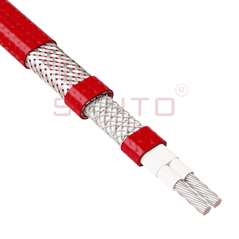
The SANTO ACC range of power-limiting heating cables is mainly used for temperature maintenance of processes and offers the advantage of a high power output at high temperatures which can reduce the n...
See Details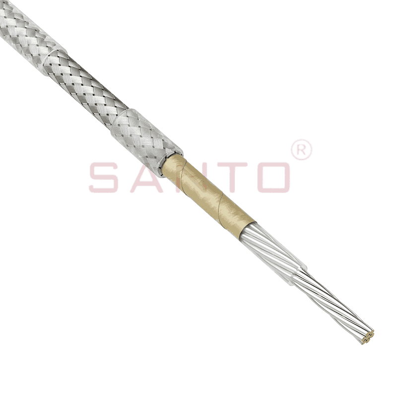
The stranded high temperature conductor is nickel plated to ensure a long life at elevated temperatures in corrosive environments. It is electrically isolated using an innovative sandwich construction...
See Details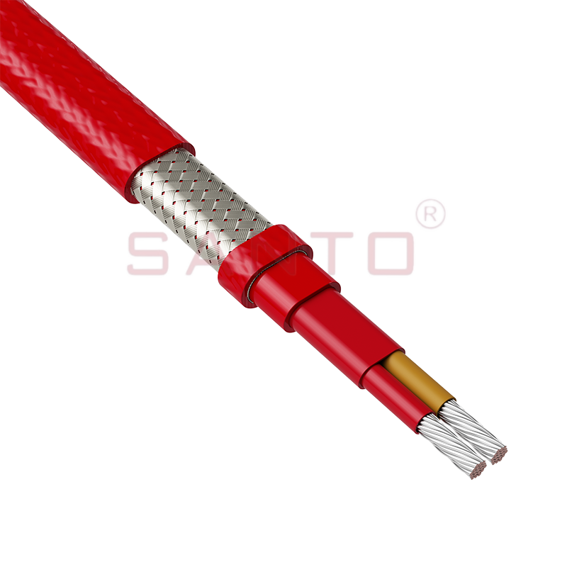
The stranded high temperature conductor is nickel plated to ensure a long life at elevated temperatures in corrosive environments. It is electrically isolated using an innovative sandwich construction...
See Details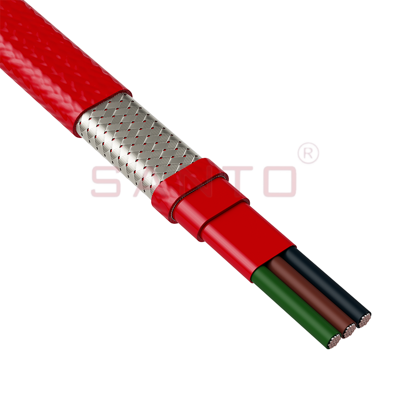
The stranded high temperature conductor is nickel plated to ensure a long life at elevated temperatures in corrosive environments. It is electrically isolated using an innovative sandwich construction...
See Details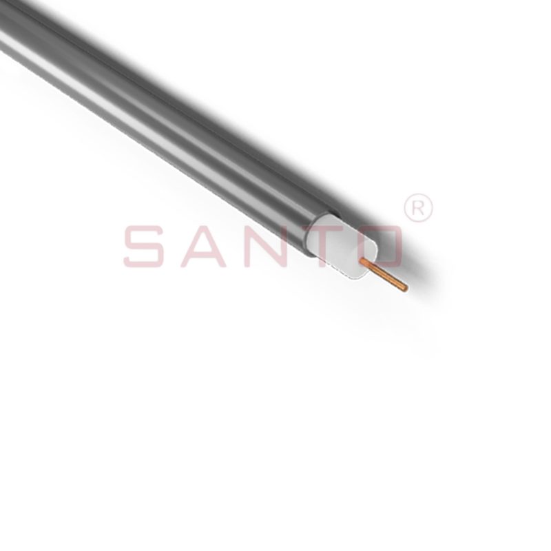
SANTO HAx mineral insulated (MI) Alloy 825 series heating cables are suitable for use in hazardous areas. They have been designed for use in freeze protection and temperature maintenance applications ...
See Details
Santo electric heating strips are widely used in key industries in China.

