 English
  English
 русский
 日本語
日本語 Español
 中文简体
中文简体
The SANTO UFA range of self-regulating heating cables is mainly used for frost protection of pipes and vessels but can also be used to maintain processes up to 65°C. These heating cables are available...
See Details
Content
Power-limiting heat tracing cables are designed to provide controlled, dependable heat for pipes, vessels, process lines, and other equipment that must remain above a specified temperature. They are particularly valuable in industrial environments where fluids may become too viscous, crystallize, freeze, or lose their required processing characteristics when exposed to low ambient temperatures.
The ACC-CT range is a power-limiting heating cable system developed for process temperature maintenance and frost protection. Its design combines a high power output at elevated temperatures with fluoropolymer outer jackets, hazardous-area suitability, multiple voltage options, and a construction intended for demanding industrial service. These characteristics make the cable appropriate for petroleum, chemical, gas, utility, and other process applications where ordinary low-temperature heating solutions may not provide sufficient performance.
Unlike a basic fixed-output cable, a power-limiting cable changes its effective power behavior as the surrounding temperature changes. This enables the cable to deliver substantial heat when the process is cold while limiting power as the temperature increases. The result is a heating system that can provide strong start-up performance without operating as a simple constant-output heater across the entire temperature range.
This article examines the construction, operating principles, applications, technical performance, installation considerations, manufacturing capabilities, and competitive advantages of the ACC-CT power-limiting heat tracing cable range.
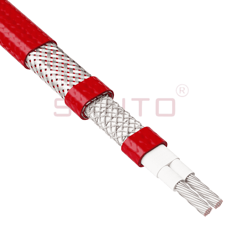
ACC-CT Power-Limiting Heat Tracing Cables
A power-limiting heat tracing cable is an electric heating cable engineered to regulate its heating output through the electrical characteristics of its heating element. When the temperature around the cable is low, the cable can produce a comparatively high level of heat. As the temperature rises, the element’s resistance changes and the available power is reduced.
This operating behavior is different from a conventional constant-wattage cable. A constant-wattage cable is generally designed to produce a predetermined output per unit length, regardless of local temperature. It may require more careful control to prevent overheating, and it cannot normally be overlapped because overlapping sections can create excessive heat concentration.
The power-limiting design provides additional flexibility. According to the supplied product information, ACC power-limiting cables may be overlapped once under the stated application conditions. Nevertheless, all overlaps, terminations, support arrangements, temperature controls, and hazardous-area requirements must be evaluated by a qualified designer before installation.
The ACC-CT series is offered in four nominal output classes:
| Model | Rated Output at 10 °C | Standard Cold-End Length | Typical Application Position |
|---|---|---|---|
| 5ACC-CT | 15 W/m | 1,219 mm | Lower-output process maintenance and frost protection |
| 10ACC-CT | 30 W/m | 914 mm | Moderate process heating requirements |
| 15ACC-CT | 45 W/m | 610 mm | Higher heat-loss systems and demanding maintenance duties |
| 20ACC-CT | 61 W/m | 508 mm | High-output applications requiring careful temperature evaluation |
The ratings in the table are reference values measured at 10 °C. Actual power output depends on cable temperature, voltage, installation conditions, thermal insulation, circuit length, and the characteristics of the controlled process.
One of the principal advantages of the ACC range is its ability to maintain a high power output at elevated temperatures. This is important in process applications where the maintained temperature is substantially above ordinary frost-protection temperatures. In such systems, a cable that loses too much output as temperature rises may require a greater installed length or more parallel heating circuits.
By providing a higher available output at increased temperatures, the ACC-CT range can reduce the number of heating cables required for a given installation. Fewer cable runs may simplify routing, reduce the number of attachment operations, and decrease the number of supply points. The final result depends on the calculated heat loss and the design requirements, but the high-temperature output characteristic is a significant advantage in industrial process tracing.
The power-limiting behavior helps reduce the risk associated with uncontrolled heat accumulation. As the cable temperature increases, its power output is limited. This is especially useful on equipment with changing thermal conditions, variable insulation performance, or occasional operating interruptions.
Power limitation does not remove the need for engineering controls. Temperature sensors, thermostats, safety temperature limiters, circuit protection, and suitable installation practices may still be required. In hazardous locations, the applicable certification documentation and calculated temperature classification must govern the final design.
All ACC products are described as having fluoropolymer outer jackets. Fluoropolymer materials are valued for their resistance to many chemicals, oils, solvents, and corrosive substances. This makes them suitable for demanding process environments where a conventional polymer jacket may deteriorate more quickly.
The product information identifies carbon steel, stainless steel, plastic-coated surfaces, and unpainted metal as possible tracing surfaces. Chemical compatibility must always be checked against the actual process chemicals, concentration, temperature, cleaning agents, and exposure duration. For aggressive organic or corrosive substances, consultation with the manufacturer or a qualified technical representative is recommended.
The ACC heating lines are identified for use in hazardous areas including Zone 1, Zone 2 for gas, Zone 21, and Zone 22 for dust. This is an important advantage for installations in chemical plants, refineries, fuel-handling facilities, gas-processing plants, and other locations where flammable gases, vapors, or combustible dust may be present.
Hazardous-area suitability is not determined solely by the presence of an approved heating cable. The complete system must be assessed, including power supply equipment, junction boxes, end seals, connection kits, temperature controls, cable routing, mechanical protection, earthing, and installation methods. The applicable certification and local electrical regulations must be reviewed before procurement and installation.
The product description identifies versions for 110 Vac, 230 Vac, and 480 Vac, with the 480 V version offering the potential for longer circuit lengths and fewer supply points. The technical information supplied for the listed specification also includes 230 V and 254 V values. Because voltage availability may vary by model, market, and certification configuration, the exact voltage must be confirmed during technical selection.
Higher-voltage operation can reduce current for the same heating power. Lower current may permit longer circuits, subject to cable characteristics, circuit-breaker ratings, voltage drop, installation conditions, and hazardous-area requirements. A longer circuit can reduce the quantity of distribution equipment and simplify large process installations. It must not, however, be selected by voltage alone; the complete electrical design must be verified.
The ACC-CT cable is supplied in a flat construction with a standard thickness of approximately 7.5 mm and a width of approximately 10.7 mm across the listed models. The flat profile can make it easier to place the cable against a pipe or vessel surface under suitable fixing and insulation arrangements.
| Characteristic | 5ACC-CT | 10ACC-CT | 15ACC-CT | 20ACC-CT |
|---|---|---|---|---|
| Rated output at 10 °C | 15 W/m | 30 W/m | 45 W/m | 61 W/m |
| Thickness | 7.5 mm | 7.5 mm | 7.5 mm | 7.5 mm |
| Width | 10.7 mm | 10.7 mm | 10.7 mm | 10.7 mm |
| Cold-end and heating-zone standard length | 1,219 mm | 914 mm | 610 mm | 508 mm |
| Weight | 180 g/m | 180 g/m | 180 g/m | 180 g/m |
The listed minimum installation temperature is -60 °C. The specified minimum bend-radius information also identifies 20 mm at -60 °C. Installation crews should avoid sharp bends, twisting, crushing, or pulling the cable beyond the permitted mechanical limits. The heating zone, cold end, termination, and connection components must be handled according to the applicable installation instructions.
The stated maximum exposure temperature during continuous energization varies by model and voltage. At 230 V, the listed limits are 230 °C for 5ACC-CT, 210 °C for 10ACC-CT, 180 °C for 15ACC-CT, and 150 °C for 20ACC-CT. At 254 V, the corresponding listed values are 225 °C, 200 °C, 145 °C, and a condition marked as not permitted for 20ACC-CT.
| Model | Maximum Exposure Temperature at 230 V | Maximum Exposure Temperature at 254 V |
|---|---|---|
| 5ACC-CT | 230 °C | 225 °C |
| 10ACC-CT | 210 °C | 200 °C |
| 15ACC-CT | 180 °C | 145 °C |
| 20ACC-CT | 150 °C | Not permitted according to the supplied specification |
The maximum exposure temperature during continuous power outage is listed as 260 °C. This value should not be interpreted as a normal operating temperature. A power outage, process upset, loss of temperature control, or temporary exposure to elevated temperature must be considered in the design and safety assessment.
Many process fluids must be held within a specific temperature range to remain pumpable or to preserve their physical properties. Viscous oils, chemical solutions, resins, wax-containing products, and other materials can become difficult to move when cooled. Heat tracing compensates for heat loss from the pipe and maintains the desired operating temperature.
The ACC-CT system can be installed along pipes, valves, flanges, supports, and other heat-loss points. The heating layout must account for the pipe diameter, insulation thickness, ambient temperature, wind exposure, process temperature, fittings, valves, supports, and required heat-up time. Heat tracing should be applied as part of a complete thermal design rather than selected solely by nominal cable wattage.
Storage vessels and process tanks often require temperature maintenance across large surfaces. The cable may be routed in parallel paths around the vessel or installed in carefully designed zones. Special attention is needed at nozzles, legs, manways, level instruments, drains, and other locations where heat loss is greater or where the cable could be damaged.
For vessels with complex geometry, the power-limiting characteristic can provide flexibility when different areas operate at different temperatures. However, the designer must still prevent excessive surface temperature and ensure that the cable remains in close thermal contact with the surface beneath the insulation.
The supplied product information identifies frost protection for pipes and vessels that require steam cleaning as a suitable application. Steam-cleaning processes can expose equipment to high temperatures, moisture, cleaning chemicals, and repeated thermal cycling. A fluoropolymer jacket can provide useful resistance in this environment, subject to chemical and temperature compatibility.
Where steam cleaning is used, the heating cable must be positioned and protected so that cleaning operations do not cause abrasion, crushing, localized overheating, or damage to end connections. The design should consider both the normal process condition and the cleaning condition.
Outdoor pipes and vessels are exposed to wind, rain, snow, solar radiation, and rapid temperature changes. Heat tracing can help prevent freezing and can maintain process fluids during winter operation. The insulation system must be weather-resistant and properly sealed, because water penetration can significantly increase heat loss and affect electrical safety.
In hazardous areas, process maintenance heating is commonly required for equipment containing hydrocarbons, solvents, gases, or combustible dust. The ACC-CT range is identified for Zone 1, Zone 2 gas, Zone 21, and Zone 22 dust applications. This allows the cable to be considered for a broad range of industrial facilities, provided the entire installation complies with the applicable certification and design rules.
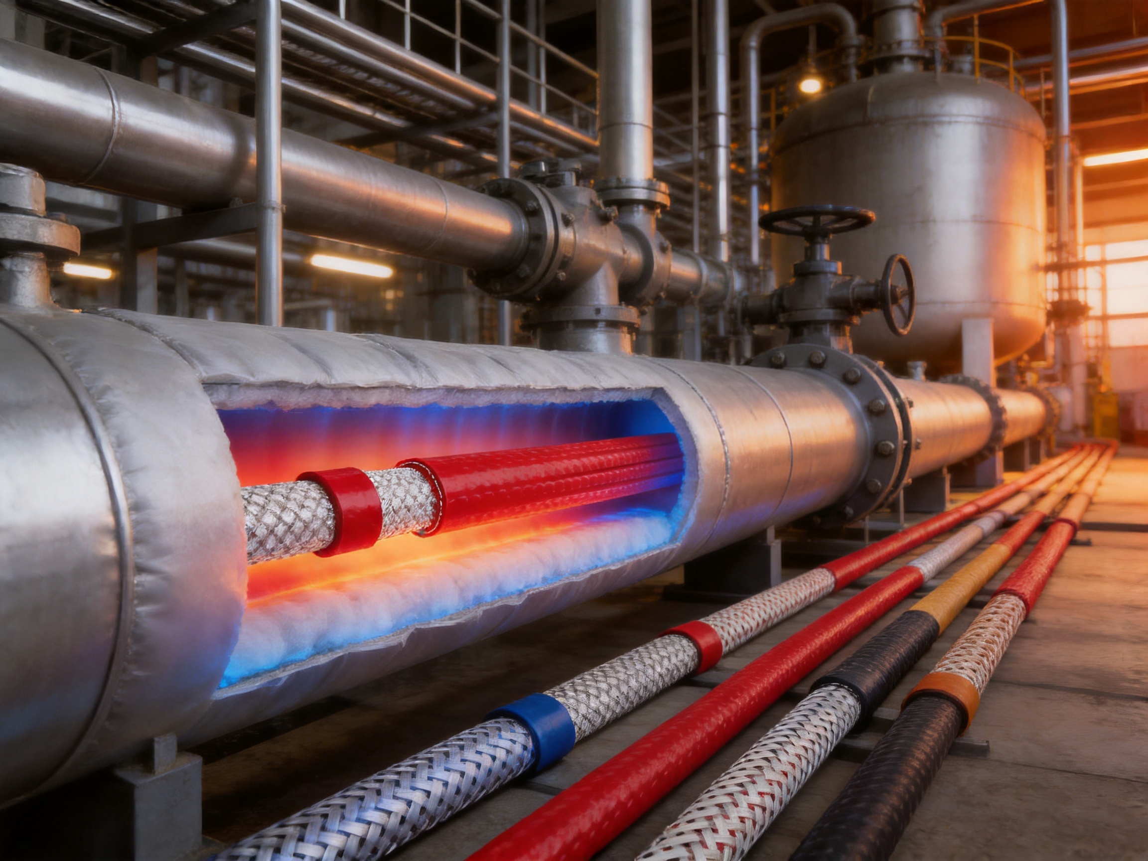
One important difference between power-limiting cables and self-regulating cables is the method used to establish the temperature classification. The supplied information states that the T-classification for ACC products must be calculated and depends on the design conditions. In some installations, a safety temperature limiter may also be required.
The calculation may consider the cable model, supply voltage, maximum operating temperature, surface material, thermal insulation, ambient temperature, installation arrangement, spacing, control method, and fault conditions. The result must be documented and compared with the requirements of the hazardous-area classification.
A temperature controller may be used to maintain the normal process temperature. A separate safety limiter can provide independent protection against excessive temperature if the primary controller fails. The safety device should be selected, installed, and tested as part of the approved system design.
Thermal insulation is essential. Without adequate insulation, heat is lost to the environment and the cable may operate for longer periods at high output. Poor insulation can increase energy consumption, reduce process performance, and affect the calculated temperature classification. Insulation must be installed after the cable has been inspected and tested, and the finished system should be clearly marked to prevent accidental damage during future maintenance.
The maximum circuit length depends on the cable type, supply voltage, start temperature, circuit-breaker characteristics, ambient conditions, and permissible voltage drop. The supplied circuit-length estimates are based on IEC 60898-compliant Type C circuit breakers and are intended only for preliminary estimation.
| Breaker Rating | Start Temperature | 5ACC-CT | 10ACC-CT | 15ACC-CT | 20ACC-CT |
|---|---|---|---|---|---|
| 16 A | -20 °C | 195 m | 100 m | 70 m | 50 m |
| 16 A | +10 °C | 215 m | 110 m | 75 m | 55 m |
| 25 A | -20 °C | 220 m | 155 m | 105 m | 80 m |
| 25 A | +10 °C | 220 m | 155 m | 115 m | 85 m |
| 32 A | -20 °C | 220 m | 155 m | 130 m | 100 m |
| 32 A | +10 °C | 220 m | 155 m | 130 m | 110 m |
| 40 A | -20 °C | 220 m | 155 m | 130 m | 110 m |
| 40 A | +10 °C | 220 m | 155 m | 130 m | 110 m |
These figures should not be used as final installation values without detailed verification. Cold-start current, breaker trip curves, supply impedance, cable resistance, voltage drop, connection equipment, and local regulations can change the permissible circuit length.
Residual-current protection is strongly recommended for safety. The supplied information recommends a 30 mA leakage-protection device for maximum safety and fire prevention. Applications that may produce higher leakage current may require a device rated up to 300 mA, subject to the applicable standards and a complete electrical safety assessment.
The use of residual-current protection does not replace correct insulation resistance testing, protective earthing, appropriate overcurrent protection, correct termination, or hazardous-area compliance. All protective devices must be coordinated with the actual circuit and installation environment.
Before installing the cable, the pipe or vessel surface should be clean, dry, and free from sharp projections, oil deposits, loose scale, and contaminants that could prevent proper contact. Damaged coatings and rough weld areas should be evaluated and treated appropriately.
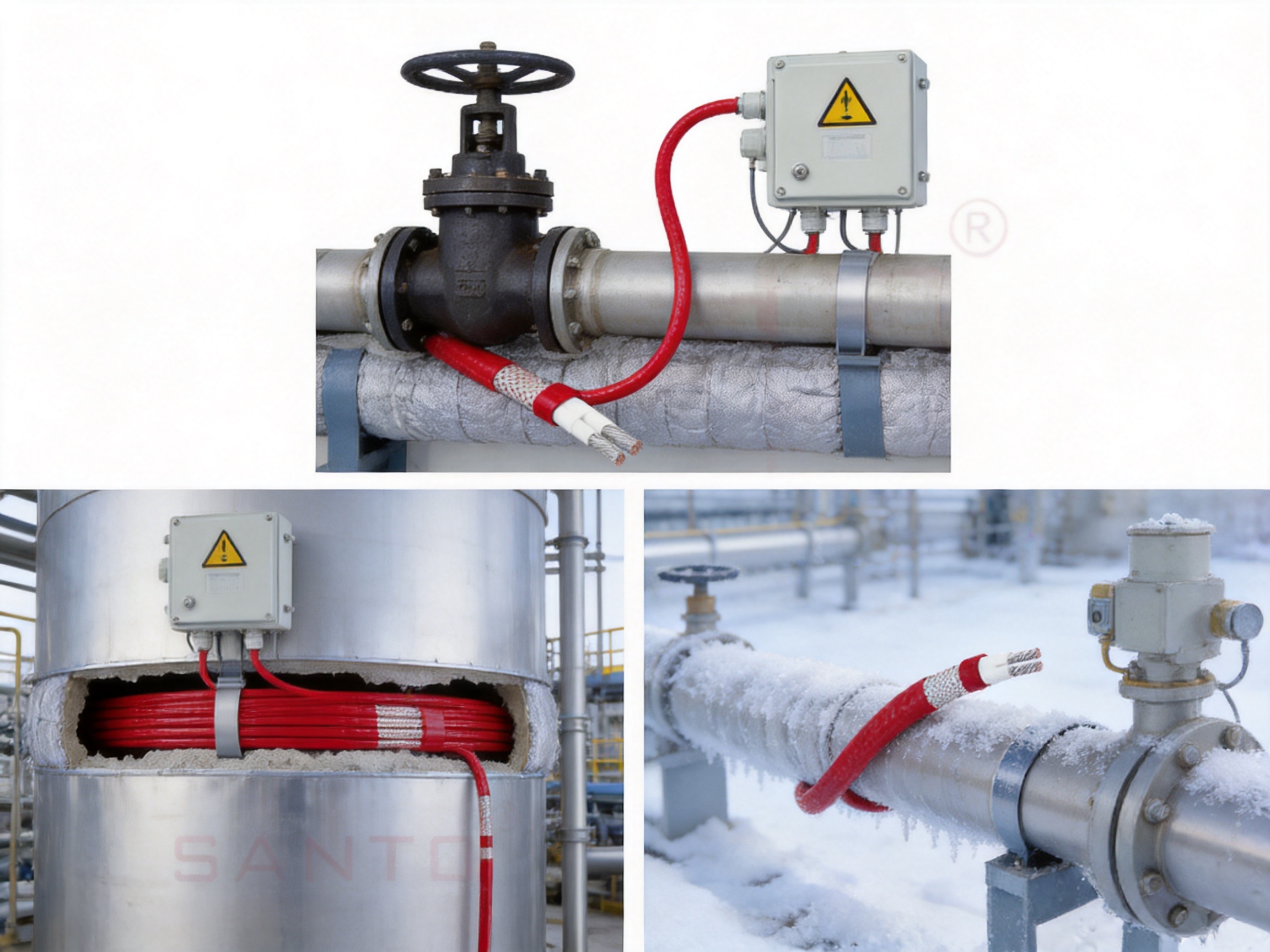
The heating cable should be routed according to the approved heat-tracing drawing. On pipes, the cable may be positioned along the lower or side section depending on the application and the need to heat valves, drains, and fittings. The cable should not be installed across sharp edges or in a way that creates excessive mechanical stress.
Power-limiting cables may have specific overlap permissions, but overlap should only be made where the manufacturer’s instructions and the approved design allow it. Unplanned overlapping, bundling, or tight crossing can create a local temperature concentration and must be avoided.
Suitable fixing materials should hold the cable firmly against the surface without cutting, crushing, or chemically attacking the jacket. Metal bands, approved tapes, or other specified fixing methods may be used depending on the application. Plastic ties or unapproved adhesives should not be substituted without checking their temperature and chemical resistance.
Mechanical protection may be required in areas exposed to impact, vibration, maintenance traffic, or repeated cleaning. Protection must not prevent heat transfer or create an unapproved thermal enclosure.
The standard cold-end and heating-zone lengths differ by model. Connection components must be compatible with the cable construction, voltage, temperature, and hazardous-area certification. Terminations should be protected from moisture and contamination, and they should be located where they remain accessible for inspection without being exposed to avoidable mechanical damage.
After installation and testing, thermal insulation should be applied continuously around the traced equipment. Gaps around flanges, valves, supports, and instrument connections can substantially increase heat loss. The finished insulation should include heat-tracing warning labels and circuit identification so that future work does not accidentally damage or energize the system.
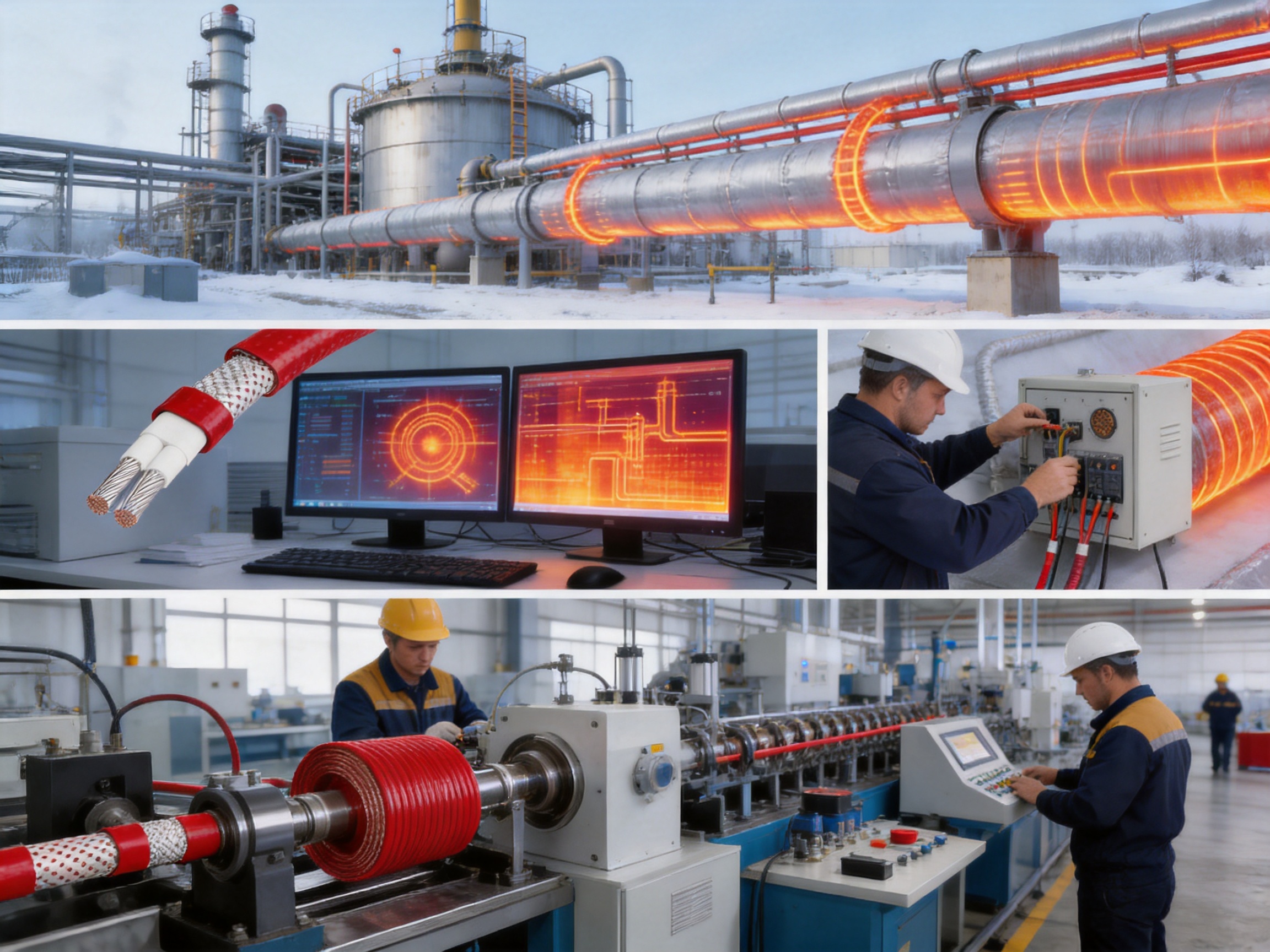
The manufacturer of the ACC-CT range operates within the electric heating industry and provides research, design, production, and manufacturing services for several categories of heating products. Its product portfolio includes self-limiting heating cables, constant-power heating cables, silicone rubber heating products, glass-fiber heating products, mineral-insulated cables, snow-melting cables, tubing-bundle heating systems, and related accessories.
This broad product base is valuable because industrial heat tracing rarely involves only one type of cable. A project may require power-limiting cables for high-temperature process maintenance, self-regulating cable for low-temperature frost protection, mineral-insulated cable for severe temperature zones, and silicone rubber heaters for flexible equipment or instruments. A manufacturer with multiple technologies can help develop a more coherent system instead of forcing every application into one cable type.
The company describes an integrated approach covering scientific research, product development, manufacturing, sales, and after-sales service. It also reports more than 35 years of industry experience, an annual output exceeding 10,000 units or product sets, more than 2,000 distributors, and business coverage across more than 85 areas. These figures indicate an established production and distribution structure capable of supporting both standard products and project-based requirements.
The company reports cooperation in product research with Harvard University in the United States and identifies multiple developments in self-limiting and carbon-fiber heating technology. Its stated development history includes research into high-temperature pipeline heating, nano far-infrared heating elements, and carbon-fiber parallel heating cables.
Research capability is particularly important for power-limiting heating products because performance depends on the interaction between conductor materials, resistance behavior, insulation, jacket materials, temperature, and installation conditions. Improvements in any of these areas can affect reliability, output stability, circuit length, and application range.
The manufacturing process for a specialized heat-tracing cable normally requires controlled preparation of the heating element, insulation extrusion, jacket application, dimensional checks, electrical testing, and final inspection. The flat dimensions of the ACC-CT cable must be maintained consistently so that the cable can be installed correctly and perform predictably along its length.
Quality control should include resistance checks, insulation resistance testing, high-voltage testing where applicable, visual inspection, dimensional measurement, jacket integrity verification, and confirmation of marking and model identification. For cables intended for hazardous areas, certification-related controls and traceability are equally important.
The company reports ISO9001 quality-system certification, national CCC certification for applicable products, explosion-proof certification, and EAC Eurasian Union certification. Certification status is product-specific, so purchasers should request the current certificate for the exact model, voltage, accessory combination, and intended hazardous-area application.
International experience can also improve project support. Industrial customers often need technical documentation, product selection assistance, circuit calculations, installation guidance, replacement supply, and multilingual communication. A manufacturer with export experience and regional distribution resources may be better positioned to assist with these requirements.
Constant-wattage cables can provide predictable output, but they normally require careful spacing and cannot be overlapped. They may also require additional temperature-control equipment to prevent overheating. The ACC-CT power-limiting design offers greater tolerance for certain layout conditions and can be used once overlapped according to the supplied product note and approved installation requirements.
The ACC range also offers a high output at elevated temperature, potentially reducing the amount of cable and number of supply points needed for high-temperature process maintenance. Constant-wattage products can remain advantageous in applications where highly uniform output and simple circuit calculations are the primary requirements, so selection should be based on the complete design rather than one feature.
Self-regulating cables automatically reduce their output as temperature increases and are widely used for low-temperature frost protection and general process maintenance. The ACC-CT range is different in that its power-limiting design is intended to retain stronger output at higher temperatures.
This makes ACC-CT particularly attractive when a process must be maintained at a relatively high temperature or when high heat loss occurs through large surfaces, long pipe runs, or difficult outdoor conditions. Self-regulating cables may remain preferable where frequent cut-to-length field installation, low-temperature maintenance, and broad local temperature variation are the main priorities.
Mineral-insulated cables can withstand very high temperatures and severe mechanical environments. They are often selected for extreme-duty applications. However, they may require more specialized handling, termination, bending, and installation procedures.
ACC-CT cables provide a fluoropolymer-jacketed alternative for applications requiring chemical resistance, high-temperature process maintenance, and hazardous-area suitability without necessarily using a mineral-insulated construction. The maximum exposure temperature and certification limits must be checked carefully before making this comparison.
General-purpose heating cables may appear economical at the purchase stage, but they may not provide the necessary chemical resistance, hazardous-area approvals, high-temperature performance, or circuit length. Using a cable that is not suited to the process can lead to premature jacket failure, inadequate temperature maintenance, production interruption, or safety problems.
The ACC-CT range is positioned as a specialized industrial product. Its value should therefore be evaluated through total installed cost, service life, circuit quantity, maintenance requirements, and process reliability rather than cable price alone.
Heat tracing efficiency depends on the relationship between generated heat and heat loss. A well-designed system uses the correct cable output, insulation thickness, control strategy, and circuit arrangement to deliver only the heat required by the process.
The power-limiting characteristic can support efficiency by providing strong heat during cold conditions and reducing output as the cable temperature rises. This may limit unnecessary energy use compared with a fixed-output cable operating continuously at its maximum rating. Actual energy savings depend on the controller, insulation, ambient temperature, duty cycle, process requirements, and cable selection.
Longer circuits made possible by suitable voltage selection can reduce the number of supply points and associated distribution equipment. Fewer electrical connection points may also simplify inspection and maintenance. Nevertheless, a longer circuit must be checked for start-up current, breaker compatibility, voltage drop, leakage current, and thermal performance.
The first step is to define the process temperature. Engineers should identify the normal maintenance temperature, minimum start-up temperature, maximum operating temperature, cleaning temperature, emergency temperature, and acceptable temperature variation.
The second step is to calculate heat loss. The calculation should include pipe or vessel dimensions, material, ambient temperature, wind, insulation, cladding, supports, valves, flanges, instruments, and the required safety margin.
The third step is to select the model and voltage. The 5ACC-CT, 10ACC-CT, 15ACC-CT, and 20ACC-CT models provide different nominal output levels. The most powerful model is not automatically the best choice because maximum exposure temperature, temperature classification, circuit length, and control requirements vary by model.
The fourth step is to establish the circuit layout. The total cable length, number of circuits, supply locations, connection accessories, breaker rating, residual-current protection, and controller arrangement should be documented.
The fifth step is to review hazardous-area requirements. The zone, gas or dust group, temperature classification, equipment protection method, certification documents, and installation rules must be verified. If a safety temperature limiter is required, it should be included in the design from the beginning.
The final step is to prepare installation and commissioning documents. These should include cable schedules, circuit identification, test records, temperature-control settings, insulation details, warning labels, and maintenance instructions.
Inspection begins before installation. The cable should be checked for cuts, flattening, jacket damage, contamination, incorrect model identification, and visible defects. It should be stored in a dry location and protected from sharp objects and excessive mechanical stress.
After installation but before insulation, the circuit should be electrically tested. Typical tests include conductor continuity, insulation resistance, protective conductor continuity where applicable, and verification of correct termination. Test voltage and acceptance criteria must follow the manufacturer’s instructions and applicable standards.
After insulation is installed, the circuit should be tested again if required by the project procedure. The insulation must be inspected for gaps, wet areas, loose cladding, and damage. Controllers and safety limiters should be function-tested to confirm that they respond at the intended temperatures.
During operation, maintenance personnel should check circuit current, controller operation, alarm status, insulation condition, connection-box integrity, and signs of overheating or water ingress. Changes to process conditions, insulation, pipe coatings, or cleaning procedures should trigger a review of the heat-tracing design.
Its main purpose is process temperature maintenance and frost protection for pipes, vessels, tubing, and related equipment. It is especially suitable where higher heat output is required at elevated temperatures.
The supplied product note states that power-limiting ACC cables can be overlapped once. Overlap must only be performed when permitted by the current product instructions, certification, and approved engineering design.
The ACC products are described as having fluoropolymer outer jackets. This provides high resistance to many chemicals and is useful in aggressive industrial environments. Compatibility with the actual chemical exposure must still be confirmed.
The product information identifies use in Zone 1, Zone 2 gas, Zone 21, and Zone 22 dust hazardous areas. The exact certification, temperature classification, accessories, and installation method must be verified for each project.
The final surface temperature depends on the cable model, voltage, process conditions, insulation, installation arrangement, and control system. Therefore, the temperature classification is design-dependent and may require a safety temperature limiter.
The 20ACC-CT model has the highest listed rated output at 10 °C, at 61 W/m. Its maximum exposure-temperature limits are lower than those of some lower-output models, so it must be selected carefully.
The listed minimum installation temperature is -60 °C. The supplied information also gives a minimum bend radius of 20 mm at -60 °C.
The general product description identifies 110 Vac, 230 Vac, and 480 Vac versions. The technical information supplied for the listed specification includes 230 V and 254 V data. The exact voltage should be confirmed for the selected model and market.
Preliminary maximum circuit-length estimates are provided for IEC 60898-compliant Type C circuit breakers rated at 16 A, 25 A, 32 A, and 40 A. Final circuit length must be calculated and verified for the actual installation.
Yes. The supplied information recommends 30 mA leakage protection for maximum safety and fire prevention. Systems with high leakage current may require a different arrangement, potentially up to 300 mA, subject to technical verification and local requirements.
The manufacturer reports long-term experience in electric heating, integrated research and production capability, a broad heating-product portfolio, ISO9001 quality-system certification, applicable product certifications, international distribution, and project-oriented technical support.
ACC-CT power-limiting heat tracing cables are designed for industrial applications that require dependable temperature maintenance, frost protection, chemical resistance, and high-temperature performance. Their strongest differentiating feature is the ability to provide substantial output at elevated temperatures while limiting power as temperature increases.
The fluoropolymer outer jacket supports use in chemically demanding environments, while the stated hazardous-area suitability allows the range to be considered for gas and dust zones when the complete system is correctly designed and certified. Multiple models, output ratings, and voltage options provide flexibility for small frost-protection circuits as well as larger process-heating systems.
The product should be selected through a complete engineering process that includes heat-loss calculations, operating-temperature analysis, circuit design, temperature classification, electrical protection, installation planning, and commissioning tests. When these steps are followed, the ACC-CT system can provide an effective alternative to constant-wattage, self-regulating, and other heating cable technologies.
The manufacturer’s experience in electric heating, research and development, product diversification, certification, and international supply provides an additional foundation for customized project support. For demanding process applications, this combination of cable performance and manufacturing capability can help customers achieve reliable heating, reduced supply complexity, and improved long-term operational confidence.
ACC Product Specification, supplied technical product information.
IEC 60898, Electrical accessories—Circuit-breakers for overcurrent protection for household and similar installations.
ISO 9001, Quality management systems—Requirements.
Hazardous-area installation principles for electrical equipment used in gas and dust atmospheres, as applicable to the project jurisdiction.
Manufacturer-provided information on power-limiting heating cables, temperature limits, circuit lengths, installation conditions, and safety recommendations.
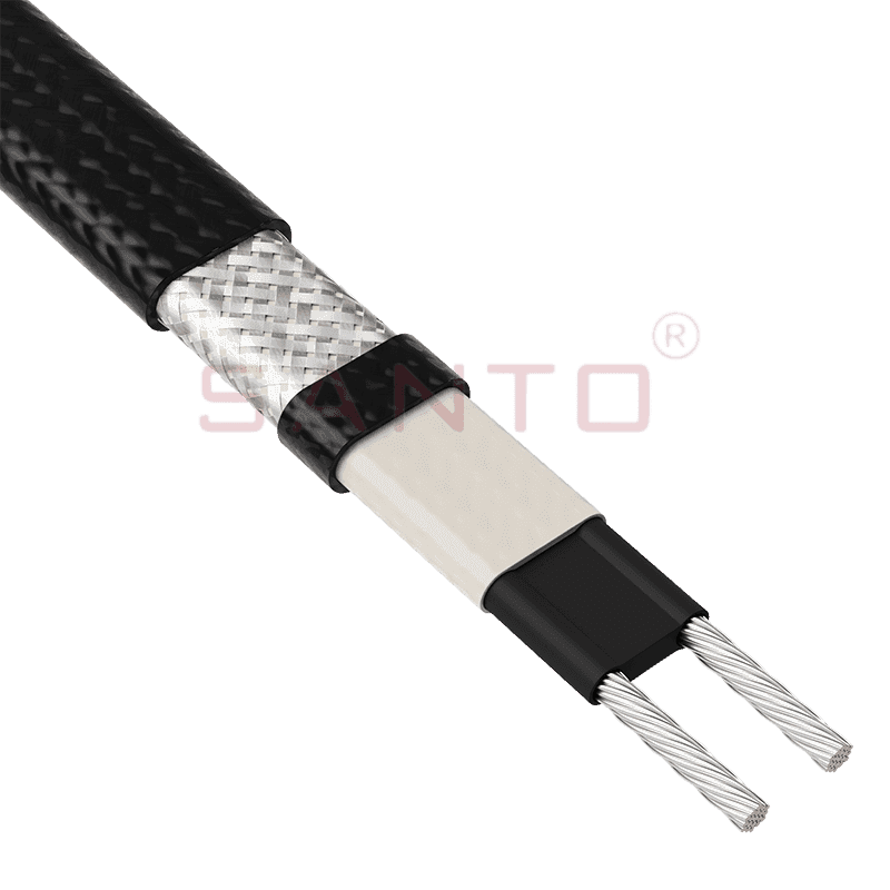
The SANTO UFA range of self-regulating heating cables is mainly used for frost protection of pipes and vessels but can also be used to maintain processes up to 65°C. These heating cables are available...
See Details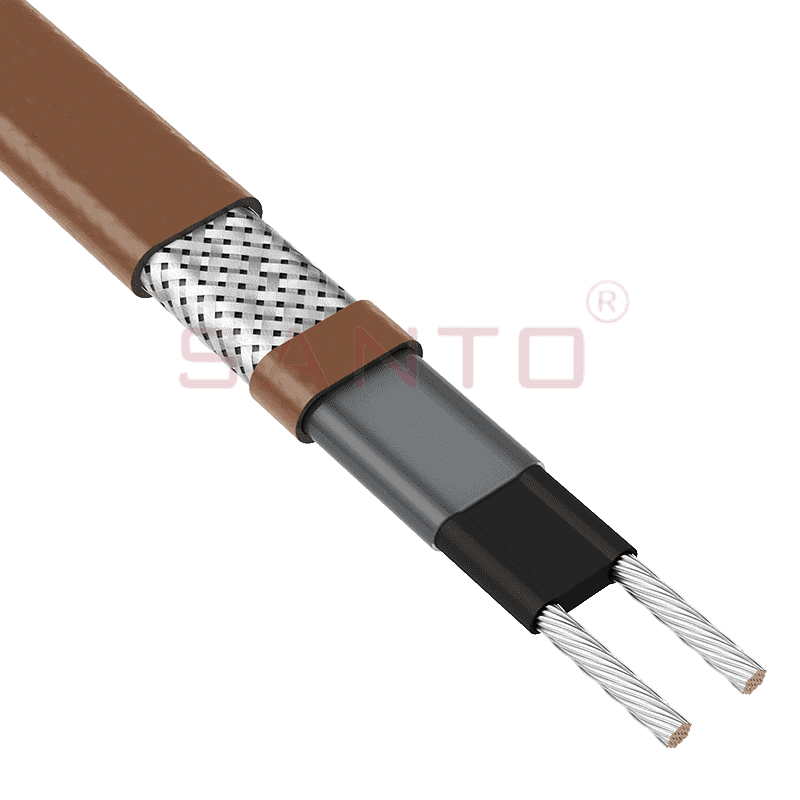
The SANTO UFB range of self-regulating heating cables is mainly used for frost protection of pipes and vessels requiring a higher power output than the UFA heating cables can supply. They can also be ...
See Details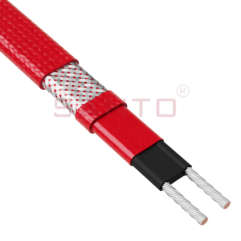
The SANTO UFC range of self-regulating heating cables is used for frost protection of pipes and vessels that require steam cleaning. They can also be used to maintain processes up to 121°C. These heat...
See Details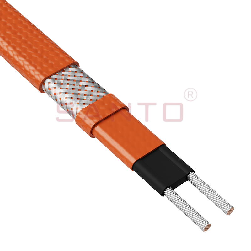
The SANTO UFO range of self-regulating heating cables is mainly used for frost protection of pipes and vessels that require steam cleaning . They can also be used to maintain processes up to 150°C. Th...
See Details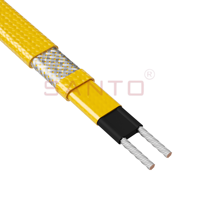
The SANTO UFD series of self-regulating heating cables are mainly used for freeze protection of pipes and vessels, but can also be used to maintain processes up to 200°C. These heating cables are avai...
See Details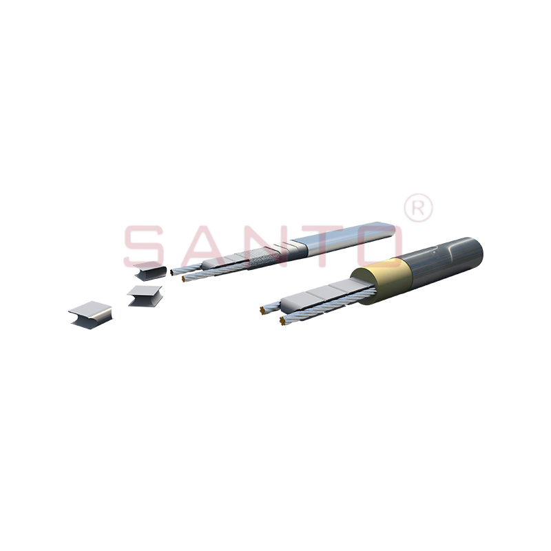
SANTO UFY heating wire is suitable for applications that maintain process temperatures up to 260 ℃ and can be steam blown; The self-regulating and parallel circuit heating wires of the UFY series are ...
See Details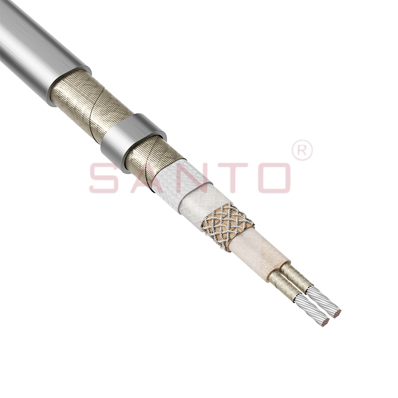
The SANTO UFM series self-regulating heating cables are mainly used for freeze protection of pipes and vessels, but can also be used to maintain processes up to 400°C. These heating cables are availab...
See Details
The SANTO ACC range of power-limiting heating cables is mainly used for temperature maintenance of processes and offers the advantage of a high power output at high temperatures which can reduce the n...
See Details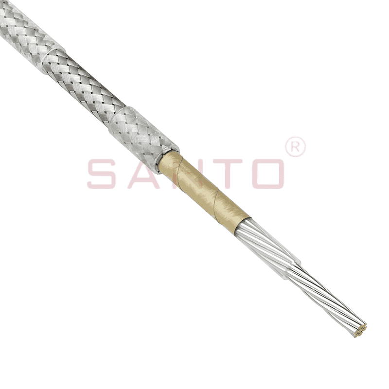
The stranded high temperature conductor is nickel plated to ensure a long life at elevated temperatures in corrosive environments. It is electrically isolated using an innovative sandwich construction...
See Details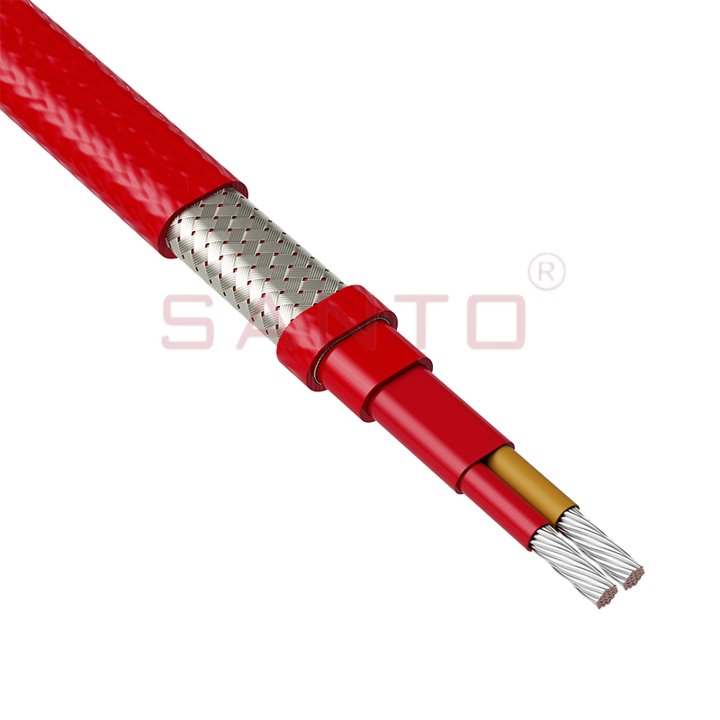
The stranded high temperature conductor is nickel plated to ensure a long life at elevated temperatures in corrosive environments. It is electrically isolated using an innovative sandwich construction...
See Details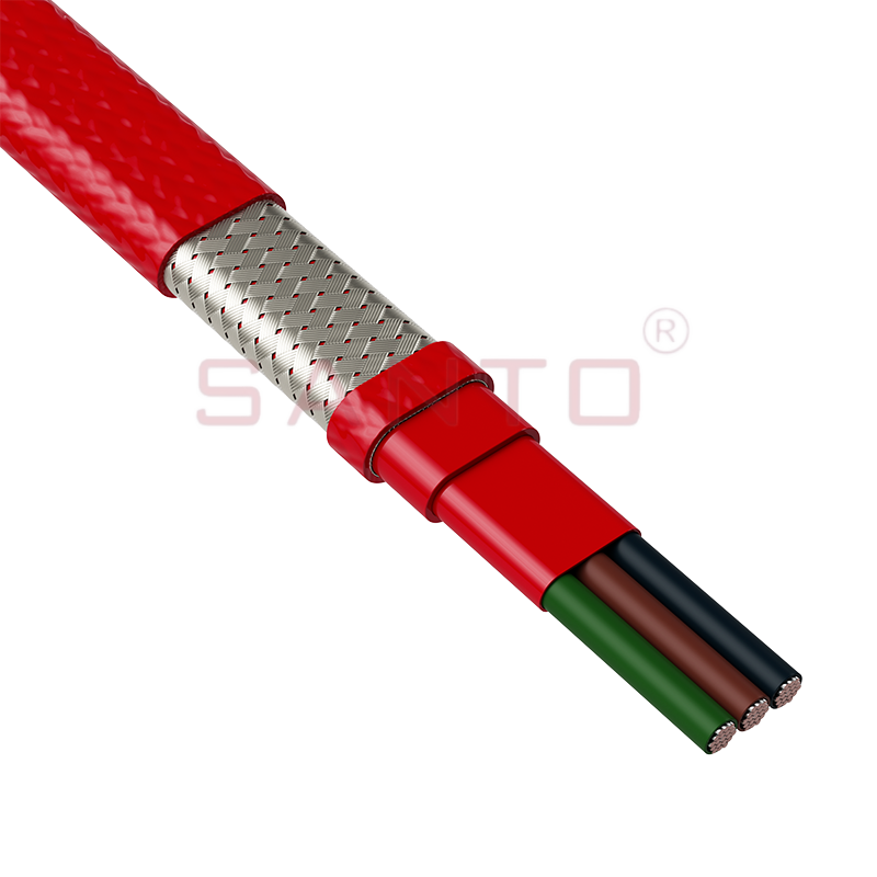
The stranded high temperature conductor is nickel plated to ensure a long life at elevated temperatures in corrosive environments. It is electrically isolated using an innovative sandwich construction...
See Details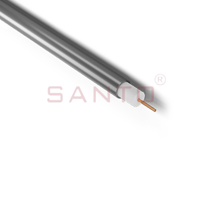
SANTO HAx mineral insulated (MI) Alloy 825 series heating cables are suitable for use in hazardous areas. They have been designed for use in freeze protection and temperature maintenance applications ...
See Details
Santo electric heating strips are widely used in key industries in China.

