 English
 English
 русский
 日本語
 Español
 中文简体

The SANTO UFA range of self-regulating heating cables is mainly used for frost protection of pipes and vessels but can also be used to maintain processes up to 65°C. These heating cables are available...
See Details
Reliable electrical connections are essential to the safe operation of heat-tracing installations. A heating cable may be carefully selected for temperature control, frost protection, process maintenance, snow melting, or pipeline protection, but the complete system can still be compromised if its connection points are difficult to install, poorly protected, or unsuitable for the operating environment. The MF-EX-20 Multi-Purpose Junction Box is designed to address these practical challenges in industrial heating cable applications.
This power junction box is intended for use with FMT, FHT, PI, and MI heating cables in hazardous areas. It provides a structured enclosure for connecting power cables, heating cables, and cold cables, while also supporting end-box configurations for series heating circuits. Its DIN-rail-mounted spring-type terminals, electrostatic charge-resistant enclosure, IP66 protection, flexible mounting options, and compatibility with multiple connection kits make it suitable for demanding industrial installations.
The product is available in two principal configurations: the MF-EX-20 and the MF-EX-20-EP. Both versions use the same general enclosure platform and provide four spring-type terminals, a maximum operating voltage of 590 Vac, and a maximum operating current of 53 A. The EP version additionally includes an earthing plate and an external earth stud, offering an enhanced earthing arrangement for projects that require this feature.
For operators, designers, contractors, and maintenance teams, the most important advantage of this junction box is that it combines electrical functionality with installation practicality. Instead of treating the enclosure, terminals, cable entries, earthing hardware, and mounting method as separate concerns, the product brings them together into a coordinated connection solution for heating cable systems.
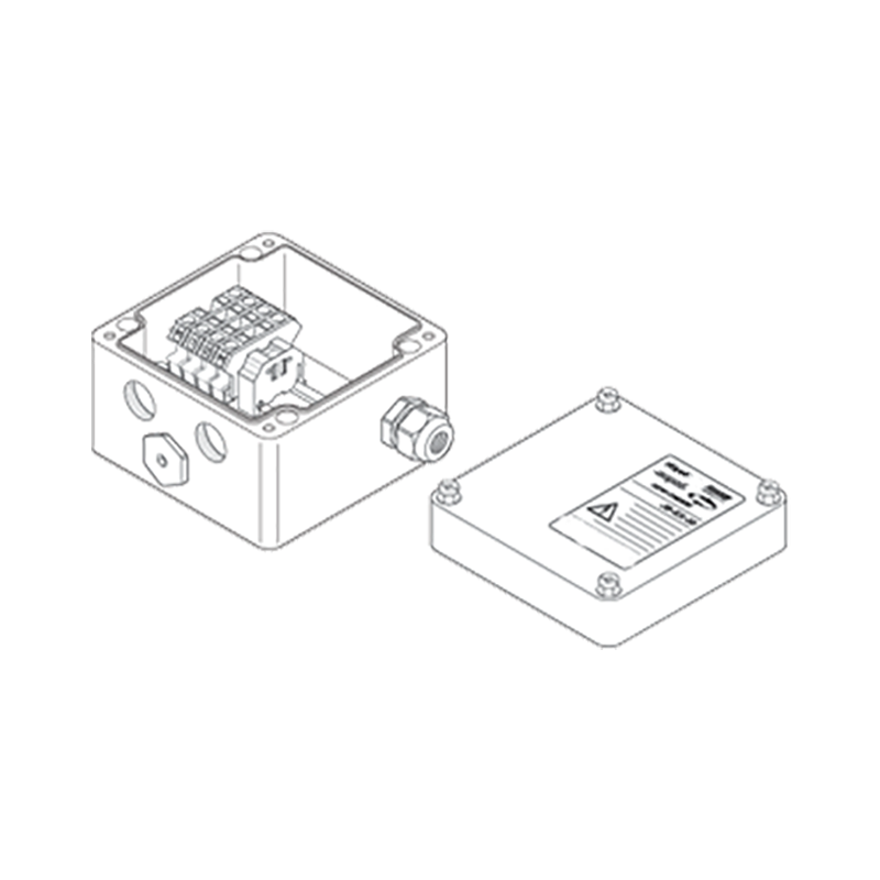
MF-EX-20 Multi-Purpose Junction Box
Content
A heating cable system normally includes more than the heating element itself. The installation may require a power supply cable, cold leads, heating cable sections, end terminations, connection kits, insulation entries, glands, stopping plugs, and support hardware. Each transition between these components must be mechanically secure, electrically reliable, and protected against moisture, dust, environmental exposure, and accidental contact.
The MF-EX-20 functions as a central connection point for these components. Depending on the selected system configuration, it can be used as a power supply box for series heating cables such as PI and MI cables, a power supply box for constant-wattage parallel heating cables such as FMT and FHT cables, or an end box for series heating cable circuits. The same basic enclosure therefore supports several common heating cable architectures.
This multipurpose design can reduce the number of different enclosure types that a contractor needs to specify and keep in inventory. It also simplifies project planning when a facility uses more than one heating cable technology. The final configuration is determined by the cable type, the connection kit, the circuit design, and the installation requirements.
The enclosure accommodates three M20 entries and one M25 entry. The M25 entry is generally associated with the power cable, while the M20 entries are used with suitable heating cable connection kits, cold cable glands, stopping plugs, or other approved accessories. M20 connection kits must be selected separately according to the heating cable being used. This approach allows the same junction box platform to work with different cable constructions while preserving a defined entry system.
FMT and FHT cables are constant-wattage parallel heating cables used for applications such as pipe freeze protection, temperature maintenance, process lines, tanks, valves, and other industrial equipment. Their connection requirements differ from those of mineral-insulated cables, particularly in relation to the cable jacket, conductor arrangement, and sealing method.
For these products, the junction box can be paired with a C20-01-F hot-applied connection kit with a plastic gland or a C20-02-F cold-applied connection kit with a metal gland. The appropriate choice depends on the cable construction, the site installation method, and the required environmental or hazardous-area arrangement.
Additional insulation entry kits, including IEK-25-04 or IEK-25-PIPE, may be used where the cable enters insulation or a pipe-tracing assembly. These components help maintain the continuity of the thermal insulation system and support a cleaner transition between the heated cable, the enclosure, and the insulated pipe or equipment.
PI and MI cables are commonly selected for applications requiring robust construction, high mechanical durability, or elevated temperature capability. Their connection arrangements are different from those of polymer-jacketed parallel heating cables and require cable-specific glands and entry accessories.
The MF-EX-20 can be used with the GL-A4-M20-KIT hazardous-area-approved gland, while the MF-EX-20-EP can be paired with the GL-44-M20-KIT hazardous-area-approved gland, according to the listed accessory selection. The IEK-20-PI insulation entry kit is also available for PI cold cable entries.
Because cable connection accessories are ordered separately, the installer can select the correct gland and connection method rather than relying on a one-size-fits-all entry. This modular approach is particularly useful in industrial projects where several cable types may be installed in the same facility.
The box and lid are manufactured from black, glass-filled engineered polymer with resistance to electrostatic charge. This material choice provides several practical benefits. A glass-filled polymer can offer a useful balance of strength, weight, corrosion resistance, and electrical insulation. Compared with a conventional unprotected metal enclosure, the polymer housing is not susceptible to ordinary surface rust and can reduce handling weight during installation.
Electrostatic charge resistance is important in hazardous-area applications because uncontrolled static accumulation can become an ignition concern in certain environments. The use of a charge-resistant material supports the enclosure’s suitability for the intended industrial service, subject to the applicable installation rules, certification requirements, and project specifications.
The enclosure uses a silicone rubber sealing gasket. Silicone rubber maintains flexibility over a broad temperature range and can support a dependable seal when the lid is correctly installed. The stated ambient temperature range for both configurations is -55°C to +55°C, allowing use in cold outdoor environments as well as warm industrial locations within the specified limits.
The lid fixing screws are captive stainless-steel screws. Captive hardware remains attached to the lid during opening and closing, reducing the possibility of dropped or misplaced screws during field maintenance. Stainless steel also provides better resistance to corrosion than ordinary carbon-steel fasteners, particularly in outdoor, humid, or chemically exposed locations.
The combination of a reinforced engineered-polymer enclosure, silicone gasket, captive stainless-steel screws, and a sealed entry arrangement gives the junction box a practical construction for industrial heating cable installations. These design elements are not merely cosmetic. They directly influence service life, maintenance effort, and the consistency of field installation.
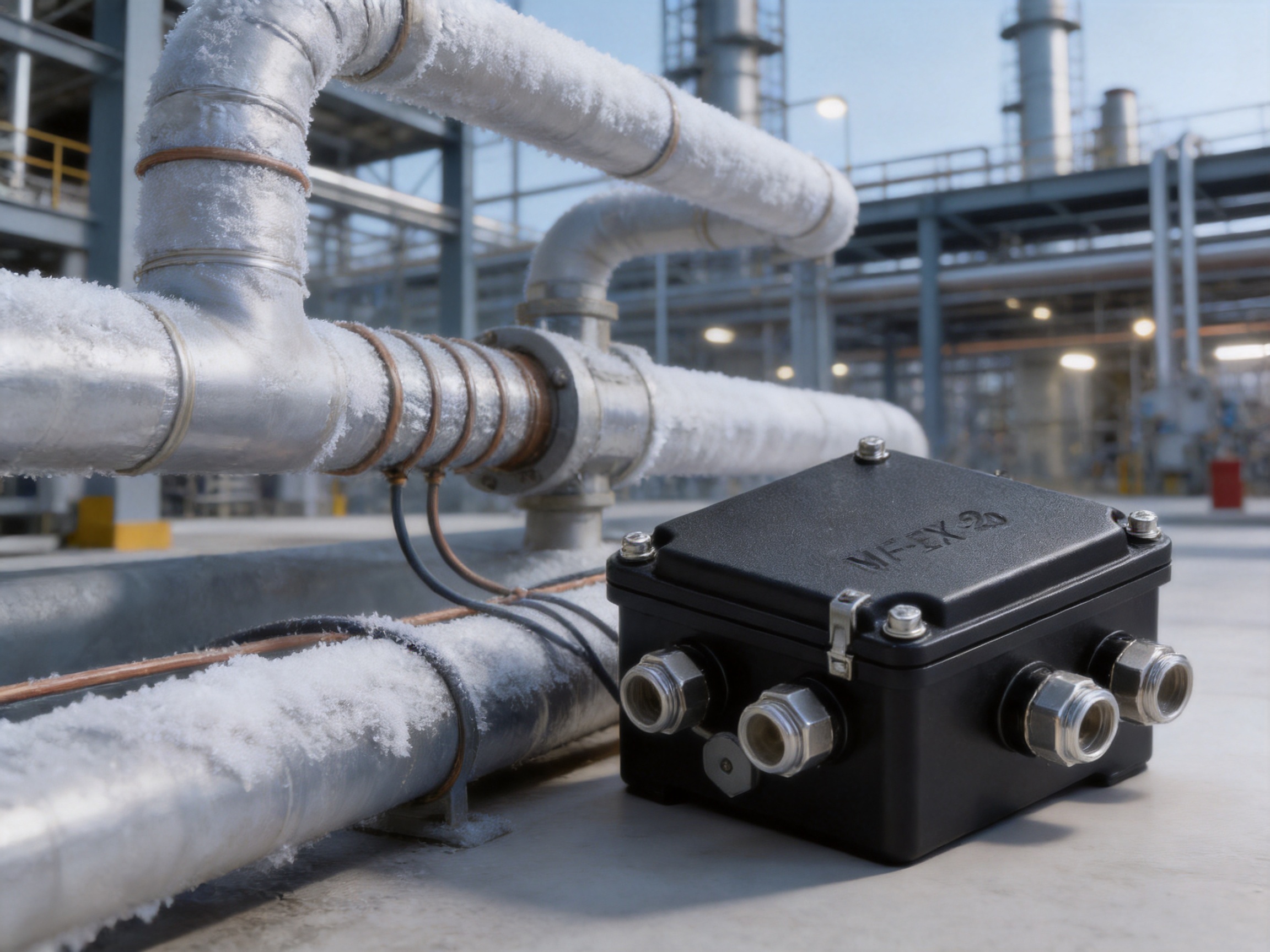
Both the MF-EX-20 and MF-EX-20-EP are listed with an IP66 ingress-protection rating. IP66 indicates protection against dust ingress and protection against powerful water jets, provided that the enclosure is correctly assembled and the cable entries are properly selected and installed.
For heating cable systems, ingress protection is especially important because junction boxes are frequently installed outdoors or in areas exposed to condensation, rain, washdown operations, airborne dust, and process contamination. Water or dust entering a connection enclosure can cause corrosion, insulation deterioration, leakage current, nuisance tripping, or eventual circuit failure.
The IP66 rating should be understood as part of a complete installation system. The enclosure alone cannot compensate for an incorrectly selected cable gland, damaged gasket, improperly tightened entry, unused open entry, or poorly fitted stopping plug. All entries must be closed or connected with compatible components, and the lid must be secured according to appropriate installation practice.
The listed operating temperature range of -55°C to +55°C provides a broad environmental window for many outdoor and industrial applications. The actual system temperature must also consider the heating cable surface temperature, process temperature, enclosure location, cable gland rating, connection-kit limits, and hazardous-area requirements.
The junction box uses DIN-rail-mounted spring-type terminals. Spring terminals are designed to maintain contact pressure on the conductor and can provide fast, repeatable wiring when correctly prepared conductors are inserted. Their use can reduce installation time compared with connection methods that require repeated tightening and retightening of multiple screw terminals.
Spring-type terminals are also useful for maintenance because they provide a clear, organized wiring arrangement on the DIN rail. The terminal layout can be inspected more easily than a crowded collection of loose connectors. This is particularly valuable when a heating cable circuit must be tested, isolated, or repaired during planned maintenance.
The standard terminal arrangement includes four spring-type terminals. The labeling is identified as 1, 2, and two PE positions, with minor formatting differences in the supplied technical table. The PE positions support protective-earth connections within the wiring arrangement. The MF-EX-20-EP adds a dedicated earthing plate and external earth stud for projects requiring the additional earthing hardware.
The maximum conductor size is 10 mm² for both solid and stranded conductors. The listed maximum operating voltage is 590 Vac, and the listed maximum operating current is 53 A. These values provide a substantial electrical capacity for many heating cable circuits, but the final allowable load must always be verified against the cable rating, circuit protection, ambient temperature, terminal conditions, installation method, and applicable electrical regulations.
A terminal jumper is available to support different wiring configurations. The product information notes that various configurations may be achieved by removing the terminal plate and using the terminal jumper as required. This feature gives the installer greater flexibility when the junction box is used for power supply, cable transition, or end-box arrangements.
| Specification | MF-EX-20 | MF-EX-20-EP |
|---|---|---|
| Primary application | Power supply or end box for compatible heating cable systems | Power supply or end box with enhanced earthing hardware |
| Entries | 3 x M20 and 1 x M25 | 3 x M20 and 1 x M25 |
| Enclosure material | Electrostatic charge-resistant glass-filled engineered polymer | Electrostatic charge-resistant glass-filled engineered polymer |
| Gasket | Silicone rubber | Silicone rubber |
| Lid screws | Captive stainless steel | Captive stainless steel |
| Earthing plate | Not applicable | Steel, zinc plated and blue chromated |
| Ingress protection | IP66 | IP66 |
| Ambient temperature range | -55°C to +55°C | -55°C to +55°C |
| Terminal quantity | Four spring-type terminals | Four spring-type terminals |
| Maximum conductor size | 10 mm², solid or stranded | 10 mm², solid or stranded |
| Maximum operating voltage | 590 Vac | 590 Vac |
| Maximum operating current | 53 A | 53 A |
| Part number | 2000-M18, approximately 0.9 kg | 2000-M19, approximately 1 kg |
One of the main advantages over a basic general-purpose junction box is the inclusion of DIN-rail-mounted spring terminals. A conventional enclosure may require the installer to source and arrange separate terminal blocks, earth terminals, end plates, jumpers, and mounting hardware. The MF-EX-20 provides an organized terminal platform as part of the junction box kit.
Spring-type terminals can shorten wiring time because the conductor is secured by a spring mechanism rather than by a conventional screw that must be tightened to a specified torque. The result can be more consistent across multiple boxes, especially when a project includes many heating circuits. Installation speed is valuable in process plants, tank farms, power facilities, commercial infrastructure, and large outdoor tracing projects where hundreds of connection points may be involved.
A clearly arranged terminal system makes it easier for maintenance personnel to identify incoming power, outgoing heating cable conductors, protective earth, and temporary or unused entries. Captive lid screws also reduce the risk of lost hardware during inspection.
The enclosure’s modular entry arrangement supports replacement or reconfiguration without requiring a completely different box design. If a cable type changes between projects, the contractor can specify the compatible M20 connection kit rather than redesigning the entire enclosure concept.
Open or improvised connections are vulnerable to moisture, dust, mechanical damage, and accidental contact. The IP66 enclosure and compatible stopping plugs create a more controlled environment for the cable transitions. The silicone gasket and sealed lid contribute to long-term environmental protection when properly maintained.
The box can be mounted on a wall or on a pipe. Four holes are molded into the base for mounting. For pipe installation, standard support brackets such as SB-100, SB-101, SB-110, or SB-111 can be selected. This flexibility helps contractors position the box close to the heated asset without fabricating a custom mounting arrangement for every location.
Wall mounting is useful in equipment rooms, electrical areas, process skids, and structural steel locations. Pipe mounting is useful when the junction box must follow a traced pipeline or when access to the nearby wall is limited. The final mounting method should account for vibration, thermal expansion, accessibility, drainage, cable bending radius, and the classification of the installation area.
The MF-EX-20 and MF-EX-20-EP share the primary electrical and environmental specifications. The key distinction is the earthing arrangement. The standard MF-EX-20 includes the junction box and spring-type terminals on a DIN rail, while the EP version includes an earthing plate and an external earth stud.
The EP version uses a steel earthing plate with zinc plating and blue chromate treatment. This additional hardware may be preferred where the project specification calls for a separate external earth connection or where the installation design benefits from a more visible and accessible earthing point.
The standard version may be selected when the project’s protective-earth arrangement is adequately handled through the supplied terminals and the applicable connection accessories. The EP version may be more appropriate for installations with specific bonding requirements, external continuity testing, or a preference for visible earthing hardware.
Both versions use the same three M20 and one M25 entry arrangement, IP66 protection, temperature range, conductor capacity, voltage capacity, and current capacity. The model decision should therefore be based primarily on the earthing requirements, project standards, hazardous-area documentation, and the selected cable connection accessories.
The junction box is a system component rather than a completely universal pre-assembled cable termination. M20 connection kits are ordered separately according to the heating cable type. Correct accessory planning is therefore essential before installation begins.
For power cables, the MF-EX-20 package includes a GL-36-M25 power cable gland according to the listed accessory information. The MF-EX-20-EP can use an optional GL-38-M25-METAL gland. The exact gland choice should be verified against cable diameter, construction, hazardous-area certification, environmental conditions, and project requirements.
For FMT and FHT heating cables, C20-01-F and C20-02-F connection kits are listed. The first is a hot-applied kit with a plastic gland, while the second is a cold-applied kit with a metal gland. The selected connection method should be compatible with the cable jacket and the required installation temperature, tools, and site procedures.
For PI and MI cable applications, GL-A4-M20-KIT and GL-44-M20-KIT options are identified for the two box variants. PI cold cable entries may use the IEK-20-PI insulation entry kit. M20 stopping plugs, including PLUG-M20-EXE-PLASTIC, are available for unused entries. Temporary rain plugs are also included in the listed kit contents for certain configurations.
Accessory planning should be completed during the engineering phase, not after the boxes arrive on site. A complete bill of materials should include the junction box, cable glands, heating cable connection kits, insulation entry kits, stopping plugs, support brackets, terminal accessories, and any required earth-bonding hardware.
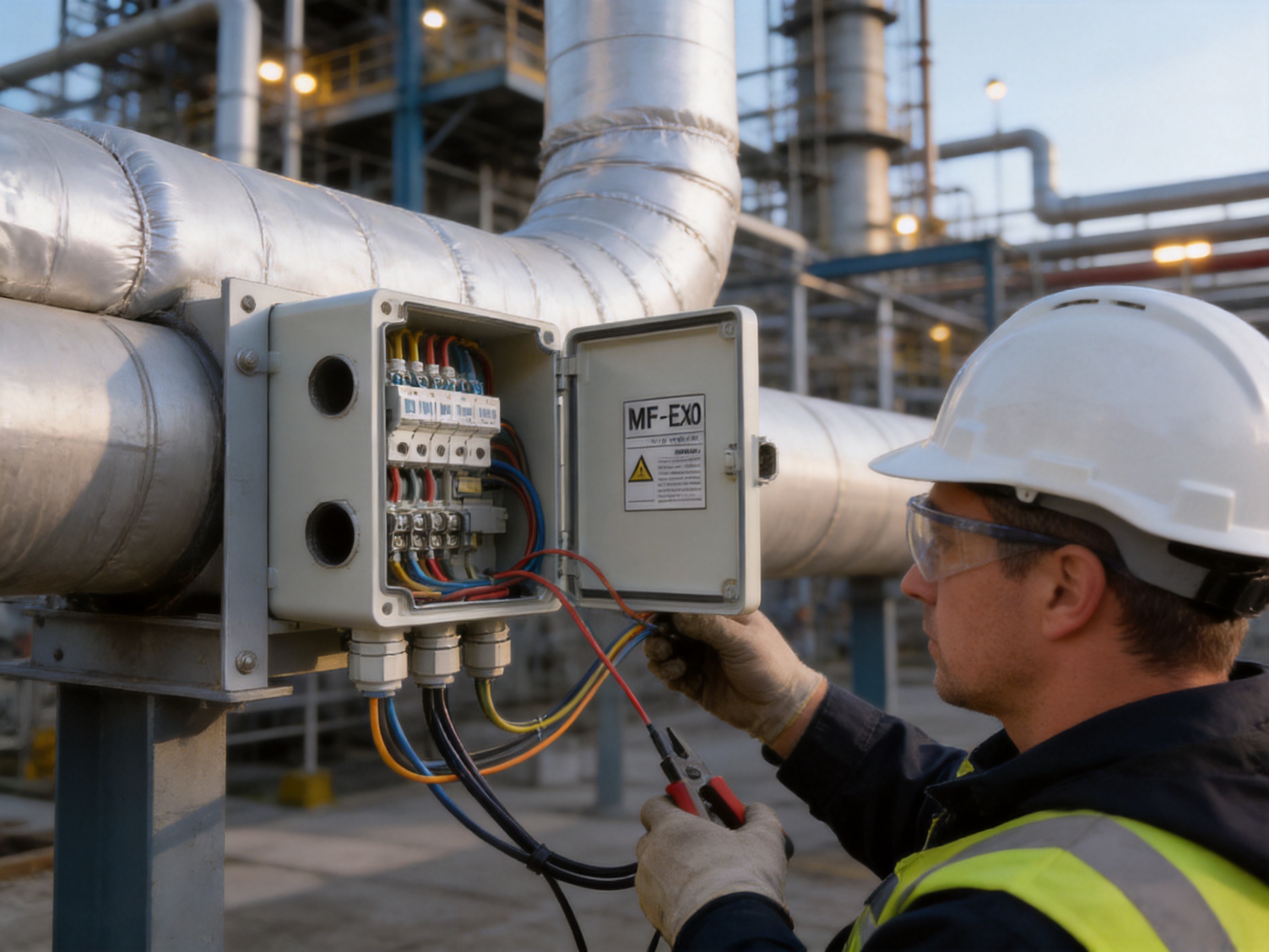
The manufacturer specializes in electric heating and thermal-control products, including self-limiting heating cables, constant-power heating cables, silicone rubber heating cables, glass-fiber heating products, mineral-insulated cables, snow-melting cables, and related accessories. This product focus is significant because a junction box designed by a heating-system manufacturer can be developed around the actual connection requirements of heating cable technologies rather than treated as a generic electrical enclosure.
Experience across multiple heating cable families allows the manufacturer to understand the differences between parallel heating cables, series heating cables, cold leads, mineral-insulated constructions, insulation entries, and termination systems. That knowledge supports a more coordinated approach to enclosure design, accessory selection, and field installation guidance.
The company reports more than 35 years of industry experience, annual output exceeding 10,000 units, a distributor network of more than 2,000, and business coverage in more than 85 areas. These figures indicate an established production and distribution organization capable of supporting both standard product supply and larger project requirements.
The reported manufacturing scope includes research, design, production, and sales. The company also describes cooperation in product research with an overseas university and the operation of product simulation and testing facilities. For industrial buyers, these capabilities are relevant because heating products must perform under combinations of electrical load, temperature, moisture, mechanical stress, and installation variation.
Quality management is identified as a central part of the company’s operating approach. The manufacturer reports ISO9001 quality-system certification and national CCC certification for its products. It also reports explosion-proof and EAC Eurasian Union certification activities for relevant products. Certification status is product-specific, so buyers should request the current certificate, marking, and technical file applicable to the exact junction box model and intended installation area.
The company’s development history includes the establishment of an electric heating instrument factory, the creation of an irradiation center, the development of high-temperature nano far-infrared heating technology, the development of carbon-fiber parallel heating cable, and the expansion of manufacturing and testing facilities. This history demonstrates a continued focus on heating technology rather than a narrow emphasis on commodity electrical accessories.
Such a development background can provide an advantage in adapting connection products to changing cable constructions and application requirements. As heating cable systems evolve, junction boxes must continue to accommodate new cable diameters, termination methods, temperature ratings, insulation arrangements, and installation practices.
A quality-oriented manufacturing process for this type of junction box should control the dimensions of the molded enclosure, the fit between lid and base, gasket placement, captive screw assembly, terminal installation, entry geometry, and earthing hardware. Consistency in these areas directly affects enclosure sealing, mechanical strength, electrical safety, and ease of installation.
The use of glass-filled engineered polymer also requires controlled molding conditions. Material preparation, mold temperature, injection parameters, cooling, trimming, and inspection influence the final strength and dimensional accuracy of the box. A stable process helps ensure that mounting holes, lid interfaces, terminal supports, and cable entries remain consistent between production batches.
Terminal assembly requires its own quality controls. The DIN rail, spring-type terminals, terminal labels, protective-earth positions, jumpers, and end plates must be installed in the correct arrangement. Electrical continuity, conductor retention, insulation spacing, and visual identification should be checked before products are released for shipment.
The MF-EX-20 is suitable for industrial heating cable systems used in petroleum, chemical processing, gas, construction, energy, solar, geothermal, and other sectors where temperature maintenance or frost protection is required.
Typical applications include pipeline freeze protection, process-temperature maintenance, tank and vessel tracing, valve and instrument protection, loading systems, pump lines, outdoor equipment, and hazardous-area process facilities. It can also be used in heating cable systems associated with deicing, frost prevention, and industrial infrastructure protection when the selected cable and enclosure configuration meet the application requirements.
In petroleum and chemical facilities, the enclosure can serve as a controlled transition point between the power supply and heating cable circuit. In gas-related installations, the hazardous-area suitability and selected cable glands must be verified against the area classification. In construction and infrastructure projects, the IP66 enclosure and pipe-mounting capability can simplify outdoor deployment.
The product is also useful in projects where the same facility contains several heating cable types. A single enclosure family can support FMT and FHT constant-wattage cables as well as PI and MI cable systems, provided that the proper connection and entry kits are selected.
Before installation, confirm the cable type, circuit voltage, maximum current, conductor size, entry arrangement, ambient temperature, hazardous-area classification, and required earthing method. Verify that the selected connection kits and glands are approved and compatible with the exact cable construction.
The mounting location should be accessible for inspection and maintenance. Avoid positioning the box where it can be submerged, exposed to direct mechanical impact, or subjected to temperatures outside the listed range. The box should be supported independently of the heating cable so that cable entries are not exposed to unnecessary mechanical stress.
When wall mounting, use the molded base holes and suitable fasteners for the substrate. When pipe mounting, use an appropriate support bracket and ensure that the bracket does not damage the pipe, insulation, protective coating, or heating cable. The box should remain stable under vibration and thermal movement.
Before cable entry, inspect the enclosure, gasket, terminals, glands, stopping plugs, and mounting hardware. Remove temporary rain plugs only when the relevant cable or permanent stopping plug is ready to be installed. Unused entries must be closed with compatible stopping plugs to maintain the required ingress protection.
Prepare conductors according to the terminal and connection-kit instructions. Do not exceed the maximum conductor size of 10 mm² or the specified electrical ratings. Maintain correct polarity, phase identification, protective-earth continuity, and cable bend radius. Ensure that the cable gland is correctly tightened and that the sealing components are not damaged or displaced.
After wiring, inspect the terminal arrangement and confirm that all conductors are fully engaged. Check the earthing connection, particularly when using the MF-EX-20-EP external earth stud. Verify that the lid gasket is seated correctly and that the captive screws are tightened evenly.
Commissioning may include insulation-resistance testing, protective-earth continuity testing, circuit resistance measurement, heating cable verification, and functional testing through the control and protection system. Test procedures must be selected according to the heating cable manufacturer’s instructions and the requirements of the project.
Although the spring-type terminal system is intended to provide maintenance-free operation under normal conditions, periodic inspection remains advisable in demanding industrial environments. Maintenance personnel should look for damaged cable glands, cracked enclosures, loose mounting hardware, gasket deterioration, corrosion on external earth connections, contamination, and signs of overheating.
The lid should not be opened unnecessarily in dusty, wet, or hazardous conditions. Before opening, isolate the circuit and follow the site’s permit, lockout, and hazardous-area procedures. After inspection, restore the enclosure seal carefully and replace any damaged accessories.
Because the enclosure is made from polymer, it should be protected from severe impact and incompatible chemicals. Cleaning agents should be suitable for the enclosure material and gasket. Abrasive tools should not be used on the sealing surfaces or terminal labels.
Heating cable circuits should be monitored for changes in resistance, insulation condition, and operating current. A junction box inspection is most effective when combined with broader heat-tracing maintenance, including control-panel checks, thermostat or sensor verification, insulation inspection, and examination of the heated asset.
The MF-EX-20 competes effectively with generic junction boxes because it is purpose-oriented for heating cable systems. Its value is not limited to the enclosure shell. It includes a coordinated combination of cable entry options, terminal arrangement, mounting flexibility, hazardous-area-oriented accessory selection, and compatibility with several heating cable technologies.
Its first competitive advantage is versatility. The same platform can be used for FMT, FHT, PI, and MI heating cables, reducing the need to manage unrelated enclosure designs across one project.
Its second advantage is installation efficiency. DIN-rail-mounted spring terminals support fast wiring and organized maintenance. The inclusion of a structured terminal system can reduce field assembly work and minimize the variability associated with separately sourced terminal components.
Its third advantage is environmental protection. IP66 protection, a silicone gasket, electrostatic charge-resistant polymer, captive stainless-steel screws, and compatible stopping plugs support use in outdoor and industrial environments.
Its fourth advantage is mounting flexibility. Wall mounting and pipe mounting can be achieved without designing a custom box support for each application. This can improve layout options and reduce installation delays.
Its fifth advantage is model choice. The standard version and EP version provide a practical way to match the enclosure to the required earthing arrangement without changing the entire connection concept.
Finally, the product benefits from being part of a broader thermal-control manufacturing portfolio. A supplier with experience in heating cables, connection kits, insulation entries, and accessories can provide more informed technical support than a general enclosure supplier unfamiliar with heat-tracing installations.
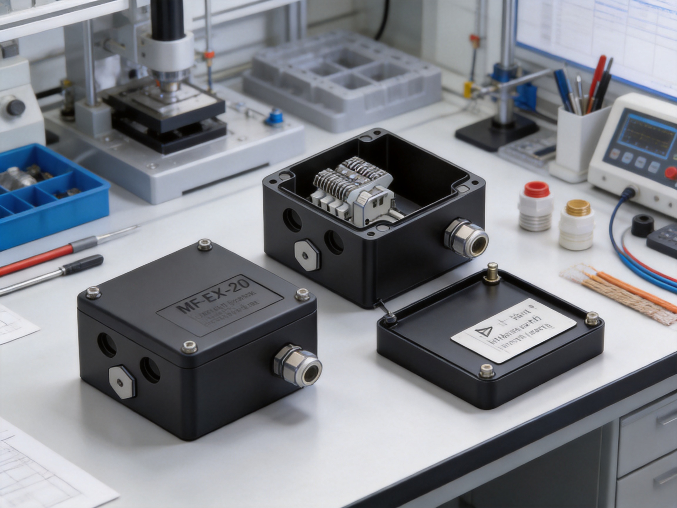
A project specification should identify the exact model, cable type, connection-kit type, entry accessories, mounting method, voltage, current, ambient temperature, and hazardous-area requirements. The phrase “junction box for heating cable” is not sufficiently detailed on its own because the required glands and termination kits differ between FMT, FHT, PI, and MI cables.
Purchasers should also confirm whether the standard MF-EX-20 or MF-EX-20-EP is required. If an external earth stud and earthing plate are specified, the EP version should be selected. If the project uses a separate approved earthing arrangement, the standard version may be appropriate, subject to engineering approval.
Weight and dimensions should be considered during layout and support design. The listed approximate weights are 0.9 kg for the MF-EX-20 and 1 kg for the MF-EX-20-EP. The full installed weight will be higher after cable glands, cables, brackets, and connection accessories are added.
Documentation should include the product data sheet, installation instructions, accessory compatibility information, hazardous-area certification where applicable, inspection records, and any project-specific test requirements. Maintaining these documents supports future maintenance and regulatory inspection.
It is an industrial power junction box used to connect power cables, heating cables, and cold cables in compatible heating cable systems. It can function as a power supply box or as an end box for selected series heating cable arrangements.
The listed compatible heating cable families are FMT, FHT, PI, and MI. The correct connection kit and gland must be selected for the specific cable type.
The product is intended for hazardous-area heating cable applications when used with the appropriate approved glands, connection kits, stopping plugs, installation methods, and certification requirements. The exact hazardous-area approval should be confirmed for the model and project location before purchase.
The enclosure has three M20 entries and one M25 entry. M20 connection kits are ordered separately according to the heating cable being used. The M25 entry is generally associated with the power cable and must be fitted with a compatible gland or stopping plug.
Both the MF-EX-20 and MF-EX-20-EP are listed as IP66. The rating depends on correct installation of the lid, gasket, cable glands, and stopping plugs.
The EP version includes an earthing plate and an external earth stud. The standard version does not include the separate earthing plate. Their principal electrical ratings, entry arrangement, enclosure material, IP rating, and temperature range are otherwise listed as the same.
The junction box includes four spring-type terminals mounted on a DIN rail. The terminals support solid and stranded conductors up to 10 mm², subject to the installation instructions and applicable electrical requirements.
The listed maximum operating voltage is 590 Vac, and the listed maximum operating current is 53 A. The actual circuit design must also consider cable rating, protection, temperature, conductor size, and local regulations.
Yes. The enclosure can be wall mounted or pipe mounted using standard support brackets. Listed bracket options include SB-100, SB-101, SB-110, and SB-111.
Heating cable connection kits are ordered separately. This allows the installer to select the correct hot-applied, cold-applied, PI, MI, or other compatible connection arrangement for the cable being installed.
The box and lid are made from black, electrostatic charge-resistant glass-filled engineered polymer. The gasket is silicone rubber, and the lid screws are captive stainless steel. The EP version adds a zinc-plated and blue-chromated steel earthing plate.
The listed ambient temperature range is -55°C to +55°C for both models. The complete installation must also remain within the limits of the heating cable, glands, connection kits, and other components.
Unused entries should be closed with compatible stopping plugs suitable for the enclosure and installation area. Temporary rain plugs should not be treated as permanent substitutes unless specifically approved for that purpose.
Spring-type terminals can accelerate wiring, provide organized DIN-rail mounting, and maintain consistent conductor pressure when installed correctly. They also make inspection and maintenance more straightforward than an unorganized collection of loose connections.
Verify the heating cable type, cable diameter, connection-kit requirement, hazardous-area classification, power cable size, operating voltage, current, mounting method, earthing arrangement, ambient temperature, required certifications, and the quantity of stopping plugs and support brackets.
The MF-EX-20 Multi-Purpose Junction Box is a specialized connection solution for industrial heating cable systems. It supports FMT, FHT, PI, and MI cable applications, provides three M20 entries and one M25 entry, and uses DIN-rail-mounted spring-type terminals for efficient field wiring. Its IP66 enclosure, silicone gasket, electrostatic charge-resistant glass-filled polymer construction, captive stainless-steel screws, and broad ambient temperature range support dependable operation in demanding environments.
The product’s multipurpose design is a significant advantage over a basic general-purpose enclosure. It can serve as a power supply box or end box, accommodate several heating cable families, and be mounted on a wall or pipe. The MF-EX-20-EP further expands the selection by adding an earthing plate and external earth stud.
Its performance depends on correct system engineering and installation. The junction box must be paired with the correct cable glands, heating cable connection kits, insulation entry kits, stopping plugs, brackets, and earthing components. When these elements are selected and installed correctly, the enclosure can help create a safer, more organized, and more maintainable heat-tracing installation.
The manufacturer’s experience in heating cables, thermal-control products, connection accessories, and industrial production provides an additional advantage. A company that understands the complete heating system can design and supply connection equipment with greater awareness of cable construction, termination practice, insulation requirements, and operating environments. For industrial users seeking a flexible junction box for hazardous-area heating cable systems, the MF-EX-20 platform provides a practical balance of compatibility, installation efficiency, environmental protection, and application flexibility.
1. MF-EX-20 Multi-Purpose Junction Box Product Specification, supplied technical product information.
2. Industrial electrical installation practice for heating cable power supply, termination, protective earthing, and enclosure maintenance.
3. Ingress protection classification principles for electrical enclosures, including dust and water protection requirements.
4. Quality-management principles for industrial product manufacturing and inspection.
5. Heating cable system engineering practice for constant-wattage parallel cables, series cables, mineral-insulated cables, cold leads, insulation entries, and hazardous-area accessories.
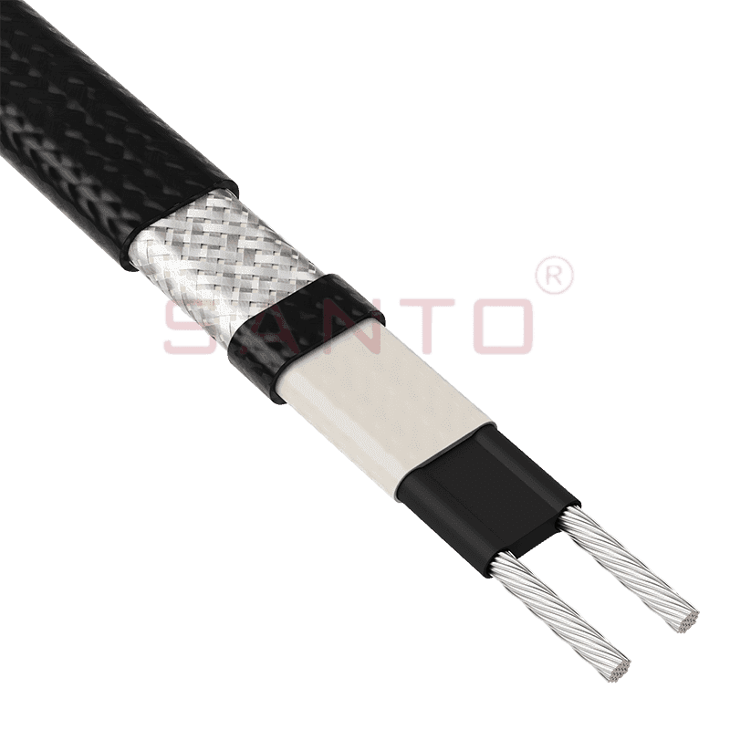
The SANTO UFA range of self-regulating heating cables is mainly used for frost protection of pipes and vessels but can also be used to maintain processes up to 65°C. These heating cables are available...
See Details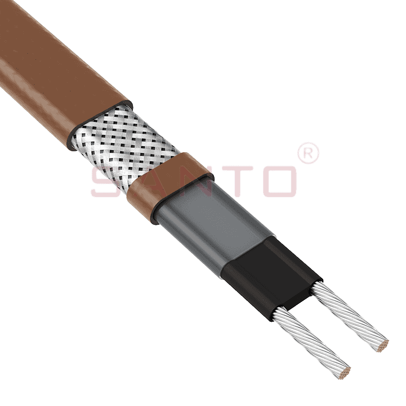
The SANTO UFB range of self-regulating heating cables is mainly used for frost protection of pipes and vessels requiring a higher power output than the UFA heating cables can supply. They can also be ...
See Details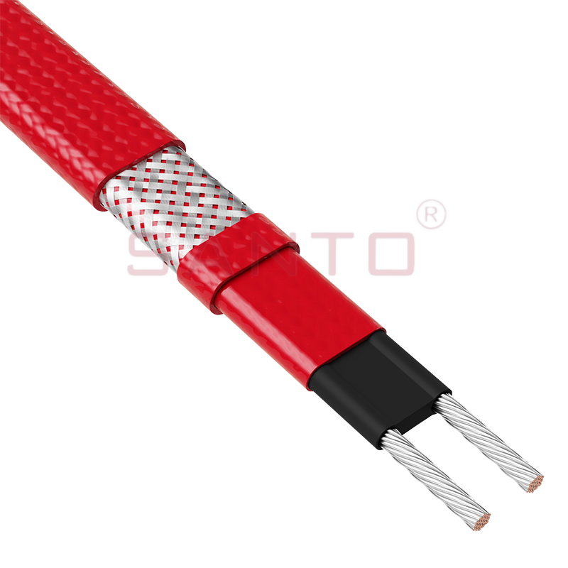
The SANTO UFC range of self-regulating heating cables is used for frost protection of pipes and vessels that require steam cleaning. They can also be used to maintain processes up to 121°C. These heat...
See Details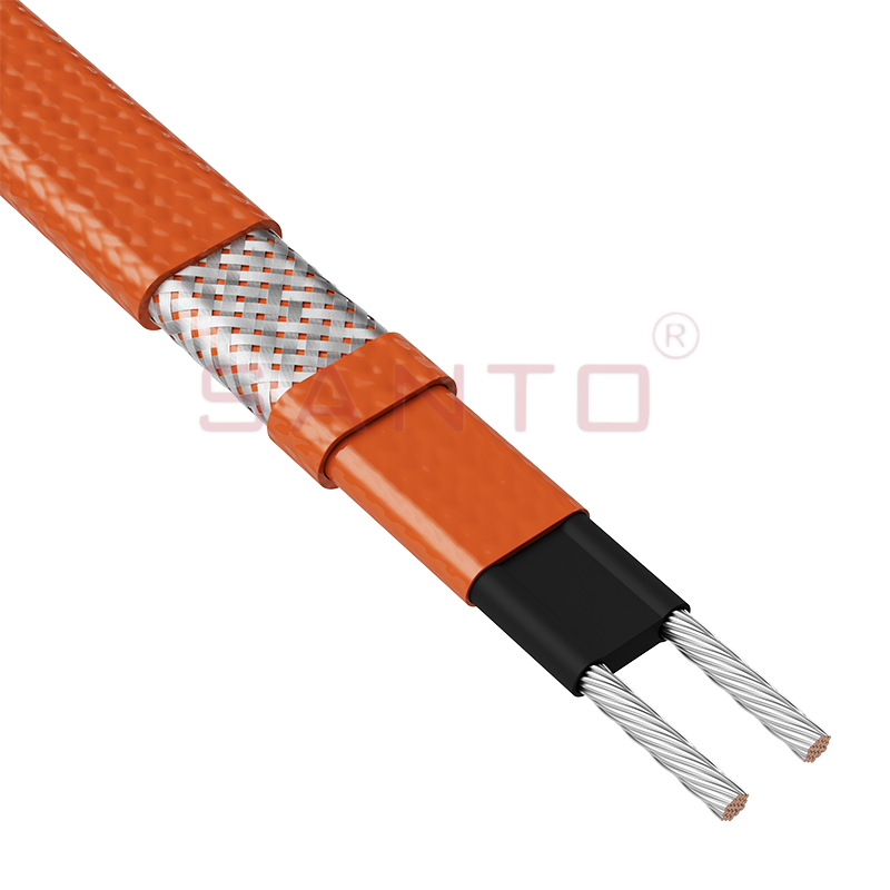
The SANTO UFO range of self-regulating heating cables is mainly used for frost protection of pipes and vessels that require steam cleaning . They can also be used to maintain processes up to 150°C. Th...
See Details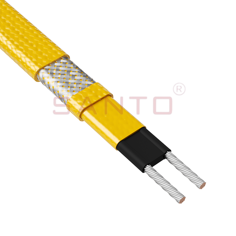
The SANTO UFD series of self-regulating heating cables are mainly used for freeze protection of pipes and vessels, but can also be used to maintain processes up to 200°C. These heating cables are avai...
See Details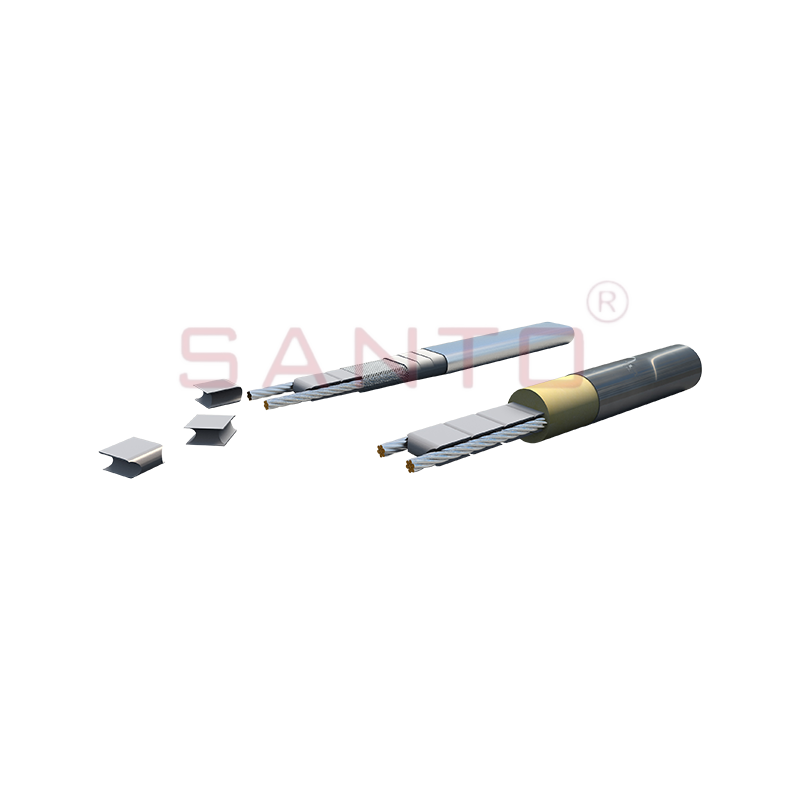
SANTO UFY heating wire is suitable for applications that maintain process temperatures up to 260 ℃ and can be steam blown; The self-regulating and parallel circuit heating wires of the UFY series are ...
See Details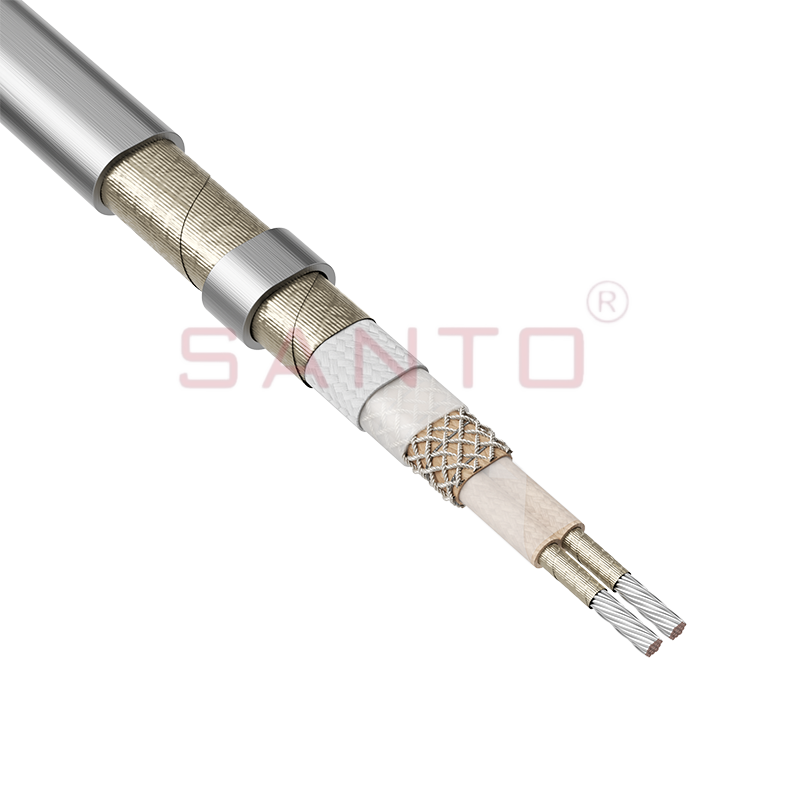
The SANTO UFM series self-regulating heating cables are mainly used for freeze protection of pipes and vessels, but can also be used to maintain processes up to 400°C. These heating cables are availab...
See Details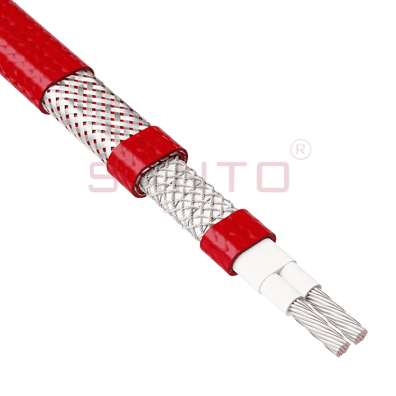
The SANTO ACC range of power-limiting heating cables is mainly used for temperature maintenance of processes and offers the advantage of a high power output at high temperatures which can reduce the n...
See Details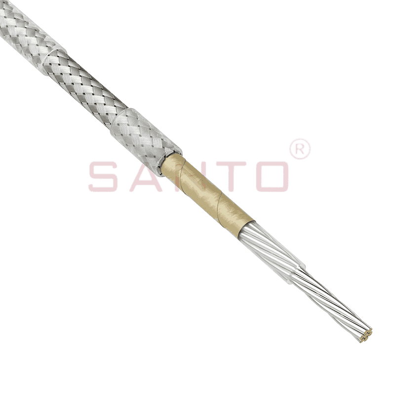
The stranded high temperature conductor is nickel plated to ensure a long life at elevated temperatures in corrosive environments. It is electrically isolated using an innovative sandwich construction...
See Details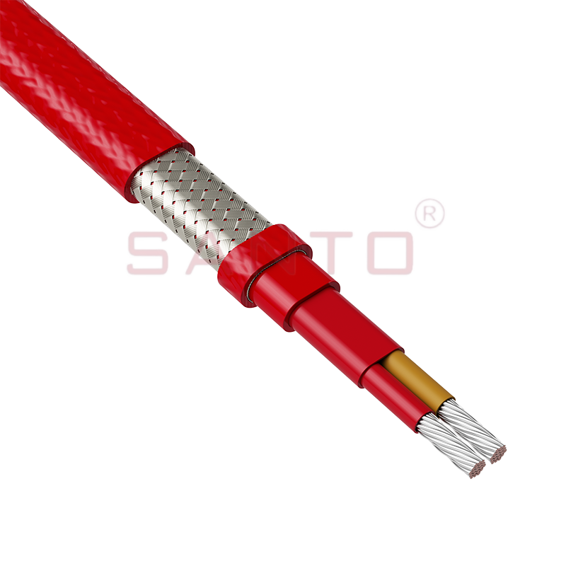
The stranded high temperature conductor is nickel plated to ensure a long life at elevated temperatures in corrosive environments. It is electrically isolated using an innovative sandwich construction...
See Details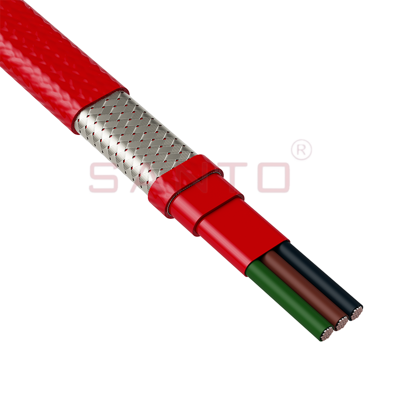
The stranded high temperature conductor is nickel plated to ensure a long life at elevated temperatures in corrosive environments. It is electrically isolated using an innovative sandwich construction...
See Details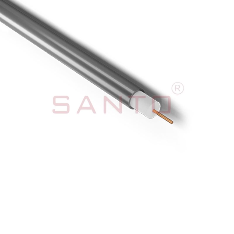
SANTO HAx mineral insulated (MI) Alloy 825 series heating cables are suitable for use in hazardous areas. They have been designed for use in freeze protection and temperature maintenance applications ...
See Details
Santo electric heating strips are widely used in key industries in China.

