 English
  English
 русский
 日本語
日本語 Español
 中文简体
中文简体
The SANTO UFA range of self-regulating heating cables is mainly used for frost protection of pipes and vessels but can also be used to maintain processes up to 65°C. These heating cables are available...
See Details
Reliable temperature control is one of the most important requirements in electric heat tracing. A heating cable or tracing circuit can provide the necessary heat, but without accurate control, the system may consume excessive energy, operate below the required process temperature, or create unnecessary thermal stress. In hazardous industrial environments, the controller must also be mechanically durable, suitable for field installation, and capable of operating with the switching equipment used by the heat-tracing system.
The E507S-LS pipeline temperature controller is designed for this purpose. It is intended for controlling electric heating systems installed in hazardous areas and can monitor the temperature of a pipeline or tank wall. The controller can operate one electric heat-tracing circuit directly or provide signal control for contactors that switch several circuits. It can also support low- or high-temperature alarm functions, helping operators identify abnormal operating conditions before they affect production, safety, or product quality.
This article examines the design, operating principle, technical characteristics, installation considerations, manufacturing strengths, and practical advantages of the E507S-LS. It also explains how the controller compares with common alternatives, including basic thermostats, indoor control panels, and general-purpose electronic temperature controllers.
Content
The E507S-LS is a field-mounted temperature controller for electric heat-tracing applications. Its primary task is to sense the temperature of the surface being protected and change the electrical state of the heating circuit when the measured temperature reaches the selected set point.
In a pipeline application, the sensing element is attached to the pipe or to a representative heated surface. When the temperature drops below the required operating level, the controller can close or open its switching contacts, depending on the selected wiring arrangement. The connected heating cable then receives power directly or through a contactor. Once the temperature rises to the control point, the switching state changes and the heating load is reduced or disconnected.
This control method is suitable for applications such as freeze protection, viscosity maintenance, process-temperature maintenance, outdoor pipe protection, tank heating, valve protection, loading-line heating, and industrial heat tracing. The controller is especially valuable where the heating system is installed outdoors or in areas containing flammable gases, vapors, dust, or other potentially hazardous substances.
Unlike a simple room thermostat, a pipeline heat-tracing controller must tolerate conditions that are common in industrial facilities. These conditions may include vibration, temperature variation, moisture, chemical exposure, long cable runs, and repeated switching cycles. The E507S-LS uses a cast-metal housing, stainless-steel components, a mechanical switching arrangement, and a remote sensing element to address these requirements.
The E507S-LS uses a liquid-filled sensing system connected to a capillary tube and sensing bulb. The published information identifies the sensor as a filling-liquid system using silicone resin, with a sensing bulb and a 9-foot, or approximately 2.7-meter, capillary. The sensor is made from 300-series stainless steel.
As the temperature at the sensing bulb changes, the filling liquid expands or contracts. This movement is transferred through the capillary to the temperature-control mechanism. When the temperature reaches the selected set point, the mechanism changes the state of the single-pole double-throw switch.
A single-pole double-throw, or SPDT, contact arrangement provides flexibility. The normally open and normally closed contacts can be used according to the control philosophy of the installation. For example, the system may be wired so that heating is energized when the sensed temperature falls below the set point. Alternatively, the contacts may be used to send a control signal to a contactor, alarm circuit, or building-management system.
The mechanical switching method has several practical benefits. It does not require a separate electronic power supply for the sensing mechanism, it can provide a straightforward contact signal, and it is familiar to electricians who install industrial heat-tracing systems. The controller can therefore be incorporated into direct-load circuits or more complex control panels.
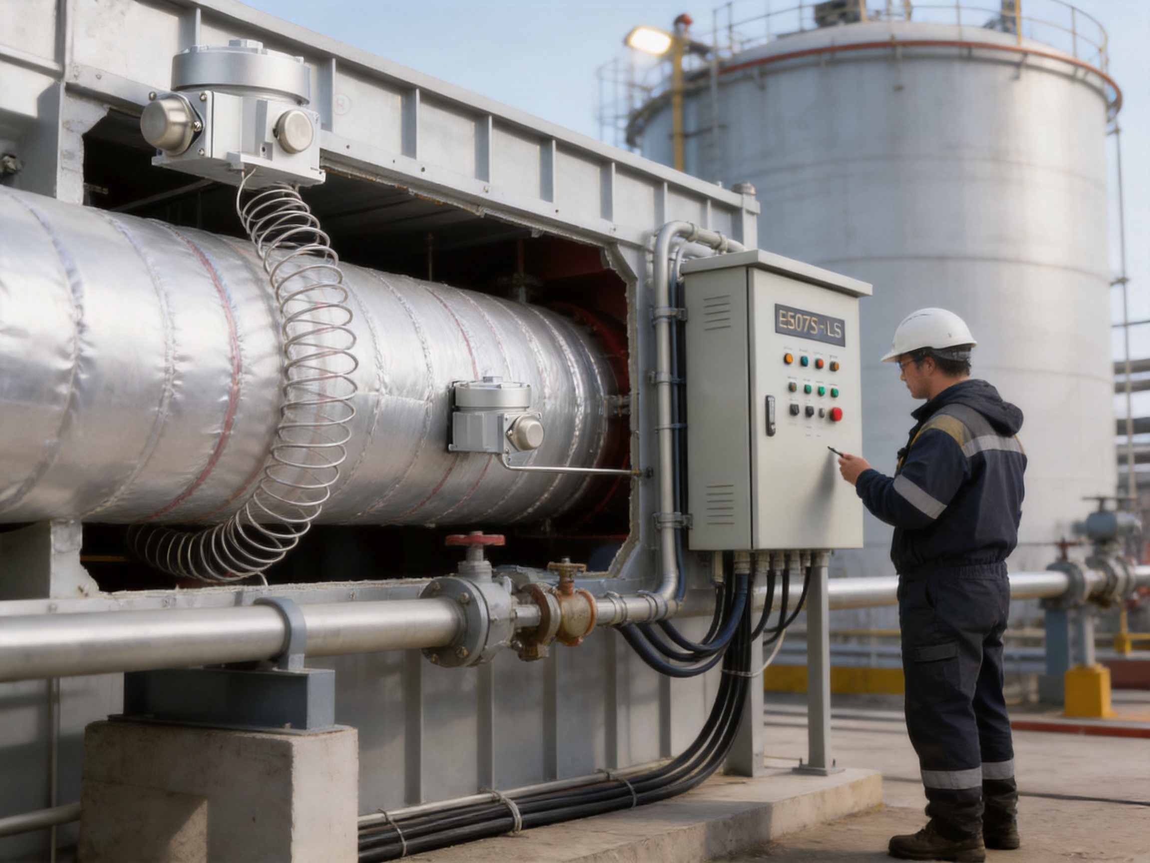
For systems with several heating circuits, the controller can be used as a master temperature signal. Instead of switching all heating cables directly through the thermostat, the contacts can control one or more contactors. This arrangement allows the E507S-LS to coordinate multiple circuits while keeping the controller’s switching duty within the appropriate electrical rating and installation design.
The following table summarizes the principal specifications supplied for the E507S-LS. Project engineers should confirm the final rating, certification requirements, wiring arrangement, and environmental limits against the latest product specification and the applicable local codes before purchase or installation.
| Item | Published specification | Application significance |
|---|---|---|
| Primary application | Electric heat-tracing control in hazardous areas | Suitable for industrial pipeline and tank heating designs when the complete installation meets area-classification requirements |
| Housing | NEMA 479 gloss cast aluminum casing with stainless-steel metal components | Provides a durable field enclosure for industrial service |
| Cable or conduit entry | One 3/4-inch, approximately 19 mm, NPT pipe joint | Allows connection to compatible conduit or cable-entry hardware |
| Set-point range | 25°F to 325°F, approximately -4°C to 163°C | Covers many freeze-protection and process-temperature applications |
| Sensor exposure limit | -40°F to 420°F, approximately -40°C to 215°C | Allows the sensing bulb to be used over a wider temperature range than the enclosure |
| Shell exposure limit | -40°F to 140°F, approximately -40°C to 60°C | Defines the ambient temperature range for the controller housing |
| Switching arrangement | Single-pole double-throw | Supports normally open or normally closed control logic |
| Electrical rating | Published as 22 A at 125/250/480 Vac | Must be checked against the exact voltage, load type, and certification requirements |
| Accuracy | ±6°F, approximately ±3.3°C | Suitable for many heat-maintenance functions where a moderate control band is acceptable |
| Dead zone | Starting temperature above 2°F to 12°F, approximately 1.1°C to 6.7°C | Helps prevent excessive switching caused by small temperature fluctuations |
| Set-point coincidence | ±3°F, approximately ±1.7°C | Indicates the expected relationship between the selected setting and switching point |
| Sensor construction | Silicone-resin-filled bulb and capillary | Provides mechanical temperature sensing without a separate electronic sensor circuit |
| Sensor material | 300-series stainless steel | Provides corrosion resistance and mechanical durability for industrial installation |
| Terminal connection | Screw terminals for 10–14 AWG, approximately 2–5 mm² conductors | Supports common industrial control and power wiring sizes |
Some source specifications use compact or imperfectly formatted notation, particularly for the electrical rating and enclosure designation. For this reason, the project documentation should always be treated as the controlling reference. The installer should verify whether the intended load is resistive, inductive, or contactor-controlled, and should confirm that the selected wiring method is compatible with the area classification.
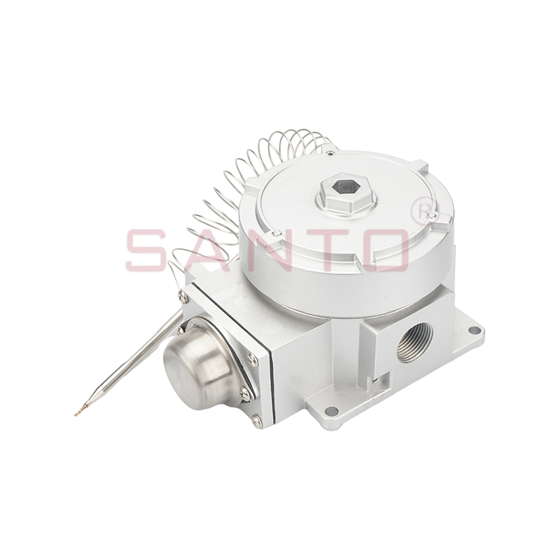
E507S-LS pipeline induction ther at for hazardous areas
The main advantage of the E507S-LS is that it is designed as an industrial field controller rather than as a general-purpose indoor thermostat. This distinction is important. A residential or commercial thermostat may provide excellent comfort control in a clean indoor environment, but it may not have the enclosure, temperature range, conduit entry, contact arrangement, or certification pathway required for a process facility.
The cast-aluminum housing provides a strong protective body for the internal mechanism. Cast aluminum is widely used in industrial electrical equipment because it combines low weight with good mechanical strength and corrosion resistance when properly finished. The gloss finish can also assist with cleaning and general surface protection.
The use of stainless-steel metal components adds another layer of durability. Stainless-steel components are particularly useful for external hardware, sensing parts, and mechanical elements exposed to moisture or industrial atmospheres. The 300-series stainless-steel sensor is well suited to applications where the sensing bulb may be exposed to condensation, cleaning conditions, or outdoor weather.
Heat-tracing control should be based on the temperature of the protected surface, not merely the air temperature surrounding the controller. The E507S-LS separates the sensing bulb from the controller housing through a capillary. This allows the controller to be mounted at a practical and accessible location while the sensor is positioned on the pipeline or tank wall.
Remote sensing improves control accuracy because the thermostat responds to the temperature that matters to the process. It also reduces the risk that the controller will respond to local solar heating, wind, enclosure temperature, or heat released by nearby electrical equipment.
The SPDT switch enables a variety of control configurations. A single circuit may be switched directly when the load and rating are appropriate. For multiple circuits, the switch can operate contactors. The same arrangement can also be used to create a control or alarm signal.
This flexibility makes the E507S-LS appropriate for both simple and expanded heat-tracing systems. A small pipe may require one heating circuit, while a process unit may contain numerous parallel circuits arranged by line, valve, vessel, or operating zone. A master thermostat can provide a common temperature reference while contactors distribute power to the individual loads.
The set-point range of approximately -4°C to 163°C covers a broad selection of industrial heating tasks. Low-temperature settings can be used for freeze prevention and frost protection. Intermediate settings can maintain process liquids, protect pumps, or prevent crystallization. Higher settings may be used for selected process-maintenance applications, subject to the heating cable design, pipe insulation, materials of construction, and hazardous-area requirements.
The controller should not be selected solely because the desired temperature falls within the nominal set-point range. The complete system must be reviewed, including the maximum pipe temperature, cable output, insulation class, process fluid, sensor location, and required temperature tolerance.
The published sensor exposure limit extends from approximately -40°C to 215°C, while the shell exposure limit is approximately -40°C to 60°C. This difference is useful because the sensing bulb may be located on a hot pipe or tank while the controller housing is installed in a cooler ambient location.
Correct placement is essential. The controller enclosure should not be mounted directly on a surface that can exceed its shell exposure limit. If the process temperature is high, the controller should be positioned away from the hot surface, with the capillary routed and protected in accordance with the installation instructions.
For a single circuit, the E507S-LS may be incorporated into the heating power circuit when the load is compatible with the controller’s electrical rating. This approach can reduce the number of components and simplify the control arrangement.
For multiple circuits, the preferred arrangement is often to use the thermostat contacts to energize a contactor coil. The contactor then supplies power to several heat-tracing circuits. This configuration offers several advantages:
It allows one temperature controller to coordinate several related heating zones.
It reduces the current carried by the thermostat contacts when the total heating load is substantial.
It makes it easier to separate power wiring from low-current control wiring.
It allows additional protection, isolation, and status indication to be included in the control panel.
It can simplify maintenance because the controller acts as a clear master control point for the heating group.
However, contactor selection must account for coil voltage, inrush current, switching frequency, enclosure requirements, and the area classification. The thermostat contact rating should not be exceeded, and the wiring should be protected against short circuits and mechanical damage.
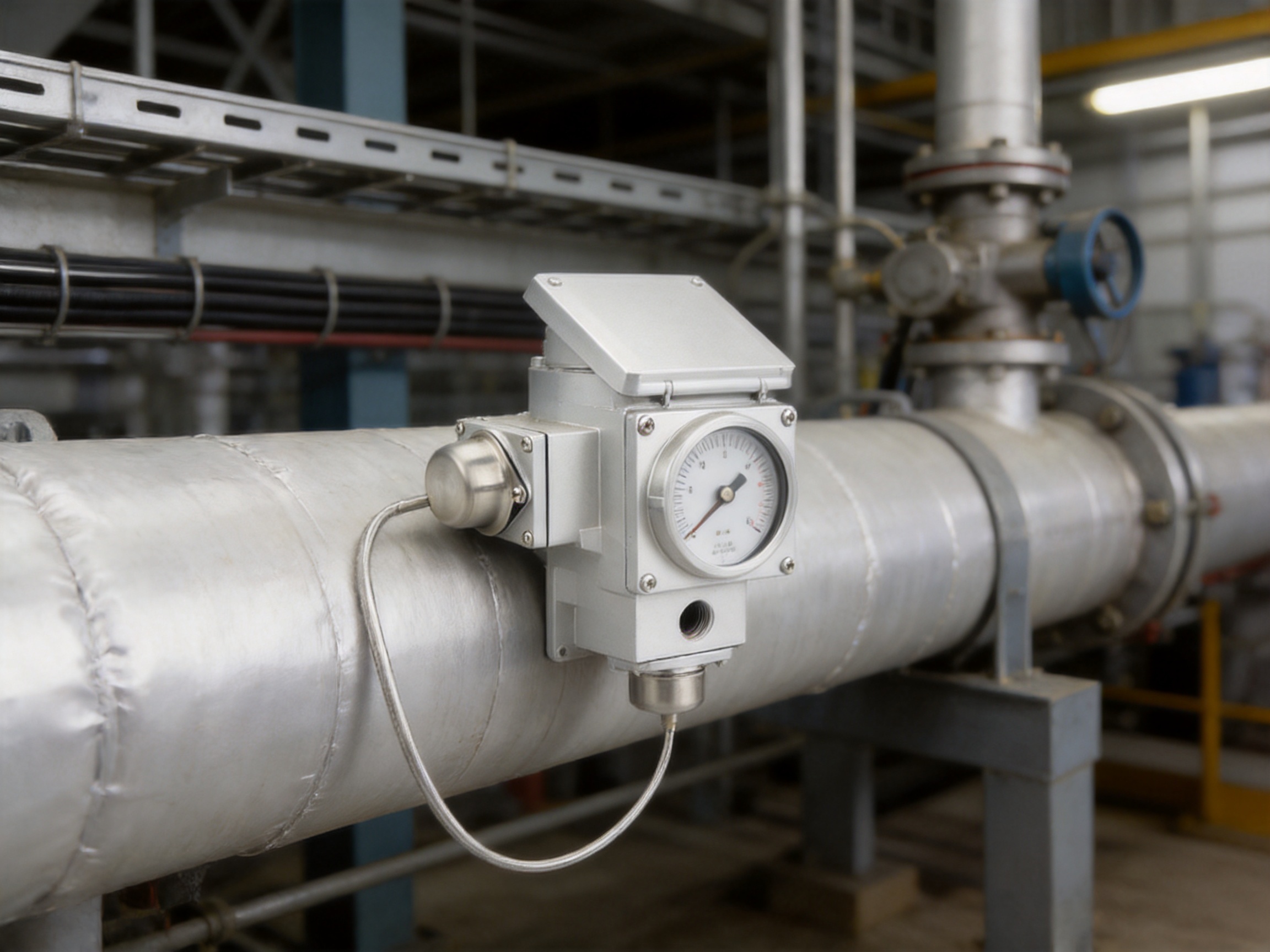
The published accuracy is approximately ±6°F, or ±3.3°C. This level of accuracy is generally appropriate for freeze protection and many heat-maintenance applications where the objective is to keep a line above a minimum temperature rather than to maintain a tightly regulated process temperature.
For example, a water line in an outdoor environment may only need to remain safely above freezing. A moderate mechanical thermostat dead zone can prevent the heating cable from switching on and off every few seconds when the pipe temperature is close to the set point.
The listed dead zone begins at approximately 2°F to 12°F, or 1.1°C to 6.7°C. The exact operating band should be verified using the current technical documentation. A wider dead zone generally means fewer switching operations, which can extend contact life and reduce electrical disturbances. A narrower dead zone may provide tighter control but may cause more frequent switching.
The listed set-point coincidence is approximately ±3°F, or ±1.7°C. This value describes the expected relationship between the selected dial position and the actual switching point. In practice, the final temperature at the pipe surface will also depend on sensor mounting, insulation quality, heat-transfer conditions, ambient temperature, and the heating cable’s output.
For critical processes, the thermostat should not be considered a substitute for a dedicated process-control system with calibrated electronic instrumentation. The E507S-LS is best applied where rugged and reliable temperature switching is more important than laboratory-level measurement precision.
The sensing bulb should be placed where it represents the temperature of the protected pipeline, tank wall, valve, or other component. It should normally be installed beneath or between heating cable passes when the objective is to sense the heated surface. The sensor should not be placed far away from the heating cable, because it may then respond too slowly or indicate a temperature different from the actual heated zone.
The bulb should be held firmly against the surface. Poor contact can introduce a thermal delay and may cause the controller to maintain an unnecessarily high or low temperature. Approved straps, clamps, tapes, or other mechanical fixing methods should be selected according to the pipe material and the operating environment.
The capillary should be routed carefully. It should not be sharply bent, crushed, stretched, or exposed to unnecessary mechanical stress. Excess capillary should be arranged in a smooth loop rather than tightly coiled. The capillary should also be protected from abrasion, moving equipment, hot surfaces beyond its permitted exposure, and areas where maintenance personnel could accidentally damage it.
The sensor should be insulated together with the pipe when the design calls for the controller to measure the maintained pipe temperature. If the sensor is installed outside the insulation, it may respond to ambient conditions rather than the pipe surface. If it is installed in an unsuitable position, the thermostat may cycle incorrectly or fail to provide the required freeze protection.
At a tank or vessel, the sensor location should reflect the part of the vessel most vulnerable to freezing or cooling. This may be near an outlet, bottom section, nozzle, valve, or low-flow area. The process engineer should consider stratification, fluid level, wind exposure, insulation discontinuities, and heat loss through supports.
Electrical installation should be performed by qualified personnel familiar with heat tracing, hazardous-area equipment, and the applicable electrical codes. The controller is only one part of the certified or code-compliant system. The heating cable, junction boxes, cable glands, conduit, contactors, overcurrent protection, grounding system, and control panel must also be suitable for the installation environment.
The published design includes one 3/4-inch NPT pipe joint. The entry should be connected using compatible conduit or certified cable-entry equipment. The installer should ensure that unused openings are properly sealed and that the selected fittings maintain the required ingress protection and hazardous-area performance.
The screw terminals are specified for conductors in the range of 10–14 AWG, approximately 2–5 mm². The actual conductor size should be selected according to the load current, voltage drop, insulation temperature, short-circuit protection, local code, and terminal capacity. All terminations should be tightened to the specified torque and checked during commissioning.
Before energization, the installer should verify the supply voltage, contact arrangement, heating-load current, contactor-coil requirements, grounding continuity, insulation resistance, and alarm wiring. The thermostat should be tested by gradually changing the sensed temperature or using an approved commissioning method. The switching action should be confirmed at the intended set point, and the result should be recorded.
In hazardous areas, no cover should be opened while energized unless the equipment and site procedures specifically permit it. Isolation, lockout, and verification of a de-energized condition are essential before inspection or service.
A heat-tracing system can fail in more than one way. A low-temperature condition may indicate a broken heating cable, an open circuit, insufficient insulation, loss of power, a failed contactor, or an incorrectly positioned sensor. A high-temperature condition may indicate a stuck contact, excessive heating output, poor sensor contact, an incorrect set point, or a process change.
The E507S-LS can be used to display low- or high-temperature alarms. The exact alarm arrangement should be confirmed from the product documentation and the project control philosophy. Alarm signals may be routed to a local indicator, control panel, supervisory system, or plant alarm network.
Alarm functions are particularly useful on unattended pipelines and remote outdoor installations. They allow maintenance personnel to identify an abnormal condition before the protected line freezes or the process material becomes too viscous to move. In chemical and petroleum applications, maintaining the correct temperature can also help preserve flow characteristics and prevent costly production interruptions.
An alarm should be treated as an operational safeguard rather than a replacement for preventive maintenance. The heating circuit should still be inspected, tested, and documented at suitable intervals.
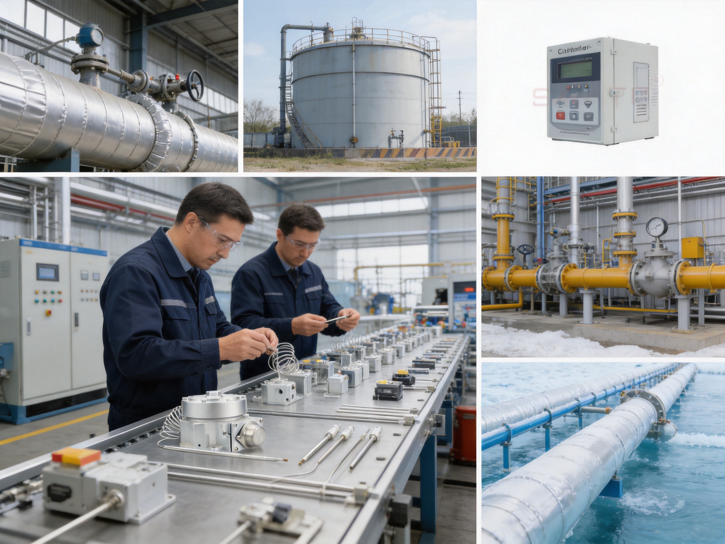
The performance of a field temperature controller depends not only on the design concept but also on manufacturing discipline. Santo Thermal Control Technology Co., Ltd. has developed its business around electric heating and temperature-control products, including self-limiting heating cables, constant-power heating belts, silicone rubber heating products, glass-fiber heating products, mineral-insulated cables, snow-melting cables, and related accessories.
This product focus gives the company practical knowledge of the complete heat-tracing system rather than only the thermostat component. Understanding heating-cable output, insulation behavior, installation layouts, start-up current, environmental exposure, and field maintenance helps the manufacturer design control products that match real heat-tracing requirements.
The company reports more than 35 years of industry experience, annual output exceeding 10,000 units or products across its product range, more than 2,000 distributors, and business coverage in more than 85 areas. These figures indicate an established production and distribution structure capable of supporting both standard products and project-based requirements.
The company states that it cooperates in product research with Harvard University in the United States and has maintained a long-term focus on new electric-heating technologies. Its development history includes work on self-limiting temperature nano far-infrared heating products, carbon-fiber parallel heating cables, and other specialized heating solutions.
Research experience in heating products can contribute to better thermostat application guidance. A controller must be matched to the thermal behavior of the heating cable and the protected equipment. A manufacturer that understands both sides of the system can more effectively advise customers on sensor location, temperature limits, control methods, and circuit grouping.
The company describes its operations as covering research, design, production, manufacturing, and sales. Such integration can reduce communication gaps between engineering and production. It can also make it easier to implement design changes, manage component sourcing, conduct product testing, and provide technical support.
For industrial customers, integrated manufacturing is especially valuable when a project requires a combination of heating cables, thermostats, control accessories, junction components, and installation guidance. Instead of sourcing each item from unrelated suppliers, the customer may obtain a coordinated package from a specialist in electric heating systems.
The company reports ISO9001 quality-system certification and national CCC certification for its products. These certifications do not automatically replace project-specific approvals, but they indicate an established quality-management framework and a formal approach to manufacturing control.
Quality management should include incoming inspection, controlled assembly, process verification, electrical testing, enclosure inspection, terminal checks, sensor calibration or functional testing, and final documentation. For a mechanical thermostat, repeatability of the switching mechanism, capillary integrity, dial performance, contact quality, and housing condition are all important.
Customers purchasing for hazardous-area projects should request the current certificates, declarations, test reports, markings, and installation instructions applicable to the exact E507S-LS version. The certification status of a general product family should not be assumed to cover every variant or every installation method.
Indoor electronic thermostats often provide greater display precision and more programmable functions, but they may require a separate power supply and may not have the enclosure or environmental resistance needed for a process site. The E507S-LS offers a simpler mechanical control method, a remote liquid-filled sensor, a cast-metal housing, and industrial conduit-entry design.
Where the application requires straightforward switching and rugged field service rather than complex scheduling, the E507S-LS can be easier to understand and maintain. Its SPDT output also provides direct wiring flexibility without necessarily requiring a digital control network.
An ambient thermostat responds to the air surrounding the device. This can be unsuitable for pipeline heat tracing because wind, sunlight, enclosure heating, and local weather may not represent the temperature of the pipe. The E507S-LS uses a remote sensor that can be attached to the actual pipe or tank wall, allowing the control decision to be based on the protected equipment.
A heating cable that runs continuously may provide reliable heat but can consume unnecessary energy during mild weather or low heat-loss conditions. Temperature control allows the heating circuit to operate only when heat is required. This can reduce operating costs and may extend the life of the heating cable and insulation system.
A digital control panel can offer data logging, remote communication, multiple inputs, and advanced alarm logic. However, it also introduces additional components, programming, power supplies, software configuration, and maintenance requirements. For a single pipeline or a group of similar heating circuits, the E507S-LS may provide a more economical and easily maintained solution.
The most appropriate choice depends on the required accuracy, number of circuits, communication needs, alarm philosophy, regulatory requirements, and operating environment. The E507S-LS is strongest where rugged local temperature control and simple contact switching are the priorities.
In the petroleum industry, the controller can support heat tracing on outdoor pipelines, sampling lines, valves, pumps, and storage tanks. Maintaining the required temperature can help prevent freezing, waxing, solidification, or excessive viscosity.
In chemical plants, heat tracing is often used to protect process lines and maintain the flow characteristics of liquids that become difficult to pump at low temperatures. The controller can be applied where the process temperature falls within the permitted set-point and sensor ranges.
In gas facilities, instrument lines, drains, pressure-control lines, and outdoor equipment may require freeze protection. Hazardous-area suitability is important because gas-processing sites may contain classified locations that require appropriately designed electrical equipment.
In construction and infrastructure, the controller can be used for exposed water lines, sprinkler systems, roof drainage, and other equipment vulnerable to freezing. The exact enclosure and certification requirements will depend on whether the site is a standard outdoor location or a classified industrial area.
In solar-energy and renewable-energy installations, heat tracing may be used on water systems, process lines, storage equipment, or outdoor service piping. The controller can provide local protection when temperatures vary significantly between day and night.
In geothermal cultivation and agricultural systems, temperature control can protect water, nutrient, and process-fluid lines. The robust sensor and adjustable set point may be useful where the equipment is exposed to weather, moisture, or washdown conditions.
The thermostat should be selected after the heat-tracing load has been calculated. The calculation should consider pipe diameter, pipe material, insulation type and thickness, minimum ambient temperature, wind speed, desired maintenance temperature, heat-loss allowances, valves and supports, and the thermal characteristics of the process fluid.
The heating cable should be selected for the required output and maximum withstand temperature. A thermostat does not compensate for an incorrectly sized cable. If the cable output is too low, the pipe may never reach the desired temperature. If the output is excessive or the sensor is poorly positioned, the pipe may overheat before the controller responds.
Sensor placement should be identified on the engineering drawings. The drawings should show the controller location, capillary route, heating-cable layout, insulation limits, junction boxes, power circuits, and alarm connections. Clear documentation helps prevent installation errors and simplifies future maintenance.
For large systems, circuits should be grouped according to similar operating requirements. Lines with different process temperatures or different insulation arrangements should not automatically share one thermostat. Multiple controllers, independent contactors, or a supervisory control system may be required.
Electrical protection should include suitable overcurrent devices and, where required, ground-fault or earth-leakage protection. The protection method should be coordinated with the heating cable manufacturer’s instructions and local regulations.
Commissioning should begin with a visual inspection. Confirm that the enclosure is undamaged, the cover is correctly fitted, the conduit or cable entry is sealed, the sensor is firmly mounted, and the capillary is free from sharp bends or crushing.
Next, verify the wiring against the approved schematic. Check the power supply, contact arrangement, contactor operation, grounding, cable identification, and alarm connections. Measure insulation resistance and continuity for each heating circuit as required by the project specification.
The temperature-control function should then be tested. Set the controller to a suitable value and observe the switching action while the sensor temperature changes. Confirm that the heating circuit or contactor responds in the intended direction. If the system includes alarms, simulate low- and high-temperature conditions using an approved method and confirm that the correct indication is produced.
Maintenance inspections should include the enclosure, entry fitting, terminal tightness, sensor attachment, capillary condition, contactor operation, heating-cable insulation, and alarm functionality. The controller set point should be checked against the process requirement, especially after maintenance work or changes to insulation.
If the heating system is connected to a remote monitoring system, alarm records should be reviewed periodically. Repeated low-temperature alarms may indicate declining insulation performance, moisture ingress, power interruption, or a failing heating circuit.
When requesting the E507S-LS, customers should provide the intended application, hazardous-area classification, ambient temperature, pipe or tank temperature, required set point, supply voltage, heating-load current, number of circuits, and desired alarm arrangement.
Customers should also confirm the required conduit or cable-entry method, sensor mounting arrangement, capillary length, enclosure requirements, certification documentation, and language of the installation manual. These details help ensure that the selected product is appropriate for the project rather than merely compatible with the nominal temperature range.
Santo Thermal Control Technology Co., Ltd. provides electric-heating products for domestic and international markets and maintains a product range that includes heating cables, heat-tracing belts, silicone rubber heaters, snow-melting systems, mineral-insulated cables, thermostats, and accessories. Its technical team can assist customers in coordinating the controller with the selected heating system.
The E507S-LS controls an electric heat-tracing system by sensing the temperature of a pipeline or tank wall and switching the heating circuit when the selected temperature is reached. It can also provide control signals for contactors that operate multiple heating circuits.
The product is designed for electric heating control in hazardous areas. However, the exact certification, marking, installation method, and permitted area classification must be confirmed from the current product documentation. The complete installation, including conduit, glands, heating cable, junction boxes, and power equipment, must meet the applicable regulations.
Yes. The controller can provide a signal to contactors that switch multiple heating circuits. The contactor arrangement should be designed according to the total load, coil voltage, switching duty, and hazardous-area requirements.
It uses a liquid-filled sensing system with silicone resin, a sensing bulb, and an approximately 2.7-meter capillary. The sensor material is identified as 300-series stainless steel.
The published set-point range is approximately -4°C to 163°C, or 25°F to 325°F. The appropriate set point depends on the process, heating cable, insulation, and required protection temperature.
The published sensor exposure limit is approximately -40°C to 215°C, or -40°F to 420°F. The controller housing has a lower shell exposure limit of approximately -40°C to 60°C, so the housing and sensor must be installed according to their separate limits.
The supplied specifications describe a liquid-filled sensor, capillary, and SPDT switch. This indicates a mechanical temperature-control design rather than a programmable electronic thermostat. The design is intended for straightforward industrial switching and field service.
It may be used to control one heating circuit when the load is compatible with the published electrical rating and the installation requirements. For larger loads or multiple circuits, a contactor-controlled arrangement is generally more appropriate. The exact wiring must be verified by a qualified electrical professional.
The sensor should be attached firmly to the pipeline, tank wall, valve, or other surface whose temperature must be controlled. It should be positioned to represent the most critical or vulnerable section and should be installed according to the heating-system design and product instructions.
A remote sensor measures the protected surface rather than the air around the thermostat. This helps prevent control errors caused by wind, sunlight, enclosure heating, or local ambient conditions.
Confirm the hazardous-area classification, desired set point, ambient temperature, process temperature, heating-load current, supply voltage, number of circuits, sensor location, conduit entry, alarm requirements, and required certifications.
Not necessarily. The E507S-LS is intended for heat-tracing temperature switching. Applications requiring highly precise measurement, data logging, programmable control, or extensive communications may require a dedicated electronic process-control system in addition to, or instead of, the thermostat.
The E507S-LS provides a practical method for controlling electric heat tracing on pipelines, tanks, valves, and related industrial equipment. Its remote liquid-filled sensor, adjustable temperature range, SPDT switching arrangement, cast-metal housing, stainless-steel components, and ability to control contactors make it suitable for a wide range of industrial heating designs.
Its principal advantage over ordinary thermostats is that it is designed around the requirements of field-installed heat-tracing systems. It can sense the actual protected surface, operate in demanding outdoor environments, and support both single-circuit and multi-circuit control strategies. The mechanical design also offers a straightforward alternative to more complex electronic systems when programmable functions and digital communications are not required.
The product’s value is strengthened by the manufacturer’s specialization in electric heating technology, broad product range, research activity, quality-system approach, and experience serving international markets. For the best result, the thermostat should be selected as part of a complete engineered heat-tracing system, with careful attention to certification, sensor placement, electrical protection, cable sizing, insulation, commissioning, and preventive maintenance.
1. E507S-LS Product Specification, manufacturer-supplied technical document.
2. Manufacturer product information for industrial heat-tracing temperature controllers.
3. Manufacturer technical information for electric heating cables, heat-tracing systems, and accessories.
4. ISO 9001 quality-management-system principles for manufacturing and product control.
5. General industrial guidance for electric heat-tracing design, installation, testing, and maintenance.
6. Applicable national and international electrical codes for hazardous-area equipment and industrial heating systems.
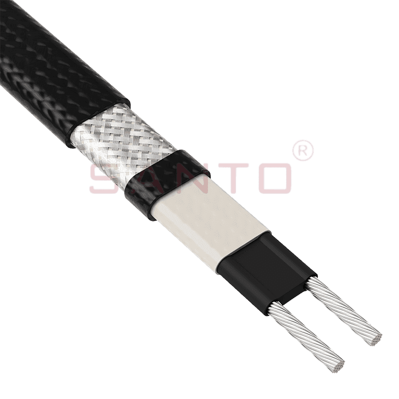
The SANTO UFA range of self-regulating heating cables is mainly used for frost protection of pipes and vessels but can also be used to maintain processes up to 65°C. These heating cables are available...
See Details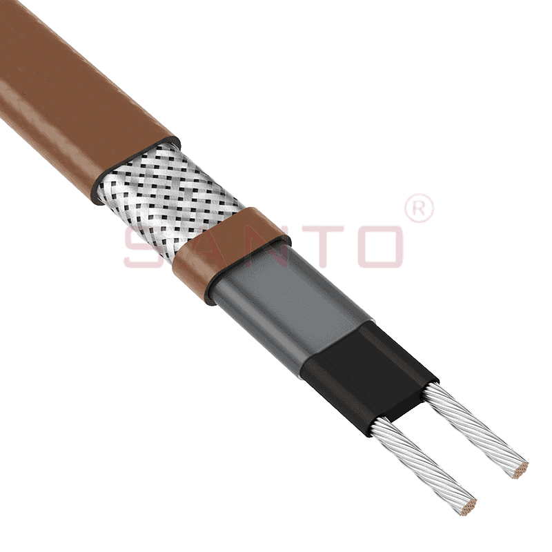
The SANTO UFB range of self-regulating heating cables is mainly used for frost protection of pipes and vessels requiring a higher power output than the UFA heating cables can supply. They can also be ...
See Details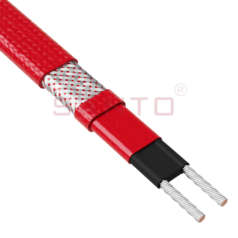
The SANTO UFC range of self-regulating heating cables is used for frost protection of pipes and vessels that require steam cleaning. They can also be used to maintain processes up to 121°C. These heat...
See Details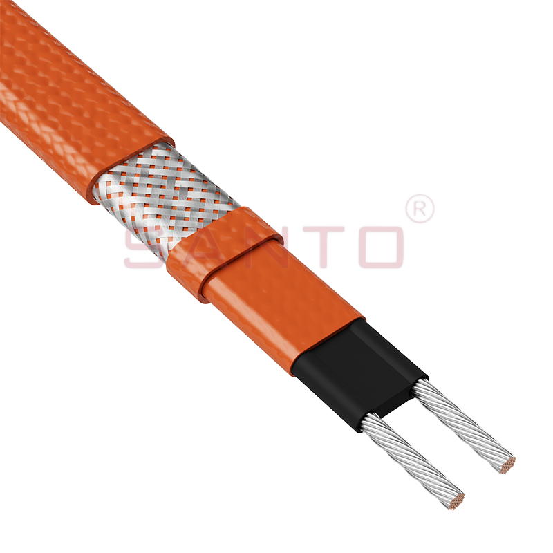
The SANTO UFO range of self-regulating heating cables is mainly used for frost protection of pipes and vessels that require steam cleaning . They can also be used to maintain processes up to 150°C. Th...
See Details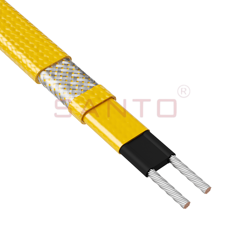
The SANTO UFD series of self-regulating heating cables are mainly used for freeze protection of pipes and vessels, but can also be used to maintain processes up to 200°C. These heating cables are avai...
See Details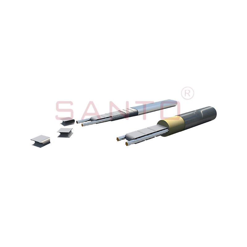
SANTO UFY heating wire is suitable for applications that maintain process temperatures up to 260 ℃ and can be steam blown; The self-regulating and parallel circuit heating wires of the UFY series are ...
See Details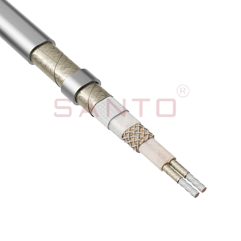
The SANTO UFM series self-regulating heating cables are mainly used for freeze protection of pipes and vessels, but can also be used to maintain processes up to 400°C. These heating cables are availab...
See Details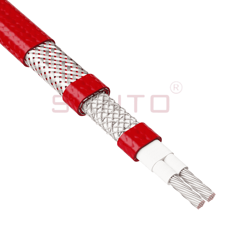
The SANTO ACC range of power-limiting heating cables is mainly used for temperature maintenance of processes and offers the advantage of a high power output at high temperatures which can reduce the n...
See Details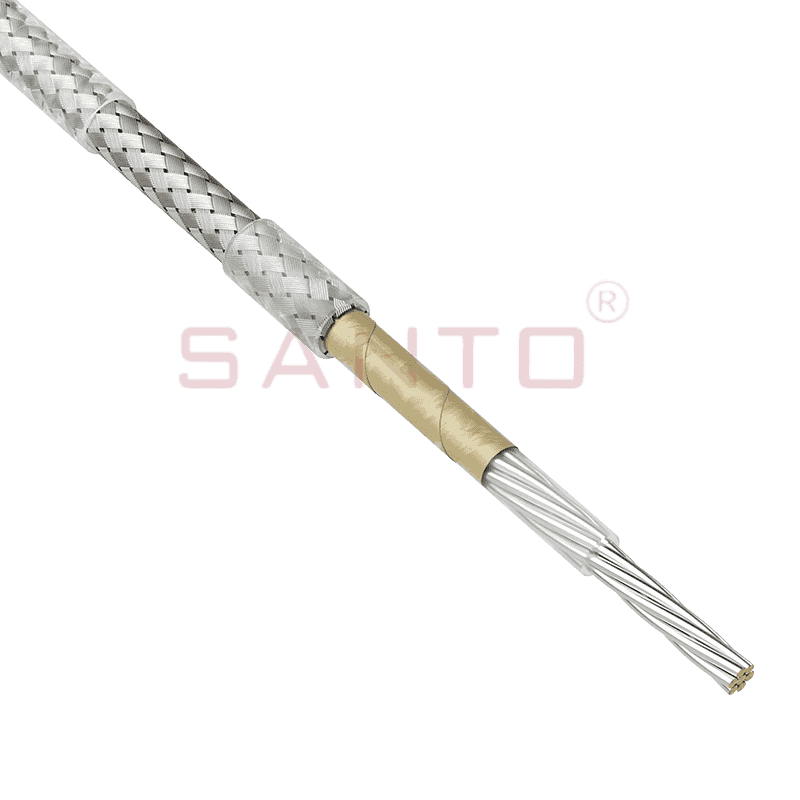
The stranded high temperature conductor is nickel plated to ensure a long life at elevated temperatures in corrosive environments. It is electrically isolated using an innovative sandwich construction...
See Details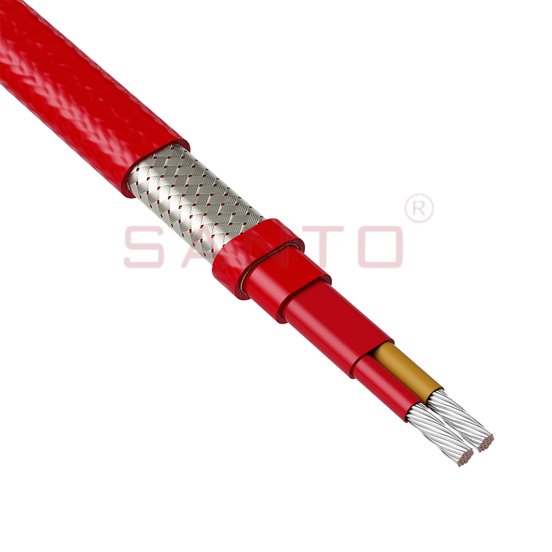
The stranded high temperature conductor is nickel plated to ensure a long life at elevated temperatures in corrosive environments. It is electrically isolated using an innovative sandwich construction...
See Details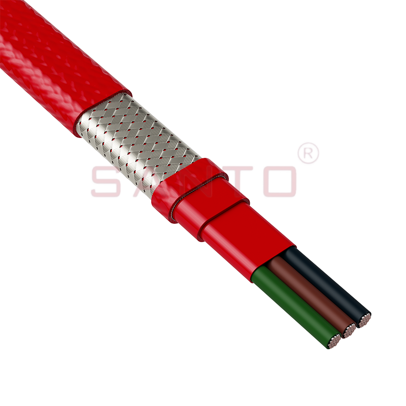
The stranded high temperature conductor is nickel plated to ensure a long life at elevated temperatures in corrosive environments. It is electrically isolated using an innovative sandwich construction...
See Details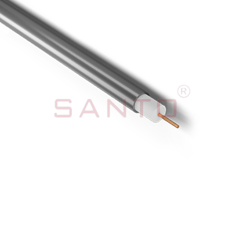
SANTO HAx mineral insulated (MI) Alloy 825 series heating cables are suitable for use in hazardous areas. They have been designed for use in freeze protection and temperature maintenance applications ...
See Details
Santo electric heating strips are widely used in key industries in China.

